I often receive e-mails requesting I look into various aspects of this legendary MIDI valve pre-amp. One request I receive a lot, has led me to develop a CR2032 adapter for the Marshall JMP-1. This replaces the factory soldered battery, with a clip CR2032 holder allowing for the battery to easily be replaced.
Something to make our lives a little easier; my CR2032 adapter for the Marshall JMP-1.
While readily available several decades ago, CR2032 batteries with solder tags have dropped out of fashion and even if you can find one, there's a good chance that it won't be exactly the same as the one that fits in your gear. As I often say "the nice thing about standards is that there are so many to chose from".
Here's the original battery in Marshall JMP-1. As you can see, it's soldered to the PCB.
My little CR2032 adapter for the Marshall JMP-1 takes care of that, well at least in the JMP-1. 🙂 It's not rocket science but can make life a little easier.
Unfortunately the main PCB has to be removed to fit this adapter and that's not an easy job. It's a process which requires time, patience and of course, the right tools but which is detailed in the installation manual, available after purchase. In fact, the installation manual goes into so much detail, it's ended up being the most comprehensive manual I've written for something so incredibly small!
This bad boy takes a lot of work to get to and doesn't come out easily but don't worry, my detailed and fully illustrated installation manual will help you all the way.
To prevent tilting during battery swap-out, the underneath of the adapter has a 2mm rubber pad which keeps it very flat and secure.
Fits like a glove and perfectly secure thanks substantial support underneath the adapter PCB.
MARSHALL JMP-1 FACTORY RESET PROCEDURE
IF YOUR JMP-1'S BATTERY ISN'T DEAD BUT YOU STILL WANT TO SWAP IT OUT, THEN PLEASE DO REMEMBER ONE THING BEFORE REMOVING IT: If you have your own edited presets in your JMP-1, you MUST back them up prior to removing the battery, otherwise they'll be lost.
If you need to reinitialise your JMP-1, here's how:
Switch off JMP-1 via the power button on the far right.
Hold down the OD1 button and the CLEAN 1 button.
While holding down these buttons, switch on the JMP-1.
Wait a few seconds while the display flashes and then release the OD1 and CLEAN 1 buttons.
Now then, you're JMP-1 might NOT reset! Yes, that's right. If your machine is locked, performing a factory reset will be useless unless you unlock your JMP-1 first.
To check the memory protect status of your JMP-1, simply try to save a patch. If the display shows 'St L', then your JMP-1 is locked and you will need to unlock it prior to performing a factory reset.
Unlocking is simple. Just follow this procedure:
Try to save a patch.
While 'St L' is displayed, press the <CHANNEL> button.
The unit will unlock.
You can now perform a factory reset as above.
MARSHALL JMP-1 MEMORY BULK DUMP
While you're here, you may find it useful to know how to dump the entire memory of your JMP-1 to a sequencer or sysex package like MIDI-Ox or SEND-SX.
Just connect the MIDI OUT from your JMP-1 to the MIDI IN of your sequencer or computer's MIDI interface.
If using a computer, select that port in your sysex package.
Now just press <Patch> and <Volume> simultaneously on your JMP-1.
Being able to convey feel to the sound after the keys are played, can transform a performance into something quite unique and almost magical. Indeed, Roland was definitely on to something when aftertouch began appearing on it’s synthesisers in the mid-eighties. Today, many classic synthesisers have aftertouch strips that either don’t work or are a shadow of what they used to be. Almost forty years later, my modern FSR-based replacement aftertouch sensor for the Roland D-50, has considerably more dynamic range and is infinitely more reliable than the second-generation transducers that Roland originally used in the D-50 and transcends the instrument into another dimension.
AT-D-50 FSR replacement aftertouch sensor for the Roland D-50.
Following on from my AT-JX-8P, AT-JX-10 and AT-AJ-2 projects and as promised, development of my AT-D-50 replacement aftertouch sensor for the Roland D-50 begins today! I'm so excited. 😀
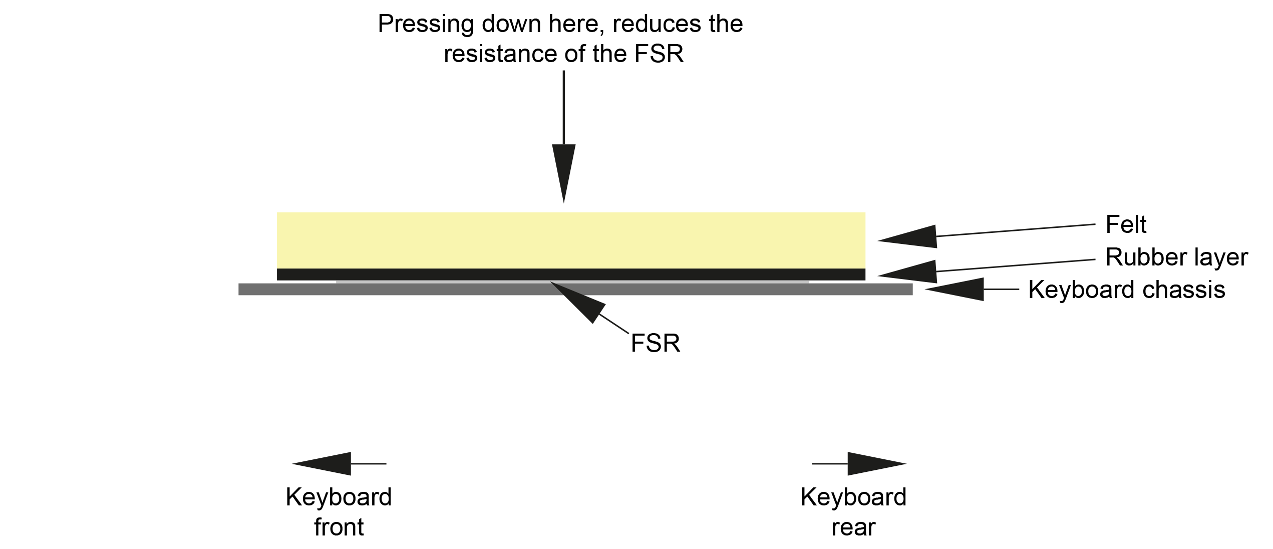
Being basically refined versions of the type of carbon-track sensors that Roland originally used but delivering a lot more dynamic range as well as other benefits, FSRs are perfect for this kind of application. In fact, modern aftertouch sensors and even some drum pads use FSRs. The principle is the same but the resistive polymer material is of a modern composition and the manufacturing process makes FSRs considerably more robust and reliable than previous pressure sensors.
Cross-section of a force sensitive resistor (FSR) illustrating how they work.
So, last night I picked up the instrument that's going to be the first to have my AT-D-50 replacement aftertouch sensor for the Roland D-50 installed. It's in lovely condition and really does deserve something special.
Here's the guinea pig for my AT-D-50. An almost pristine example of this classic synth.
Before I opened up this D-50, I thought I'd reacquaint myself with the aftertouch buffer / amp circuit. Wow, a little more involved than pervious synthesisers and Roland started using SMD passives. That's gonna be fun!
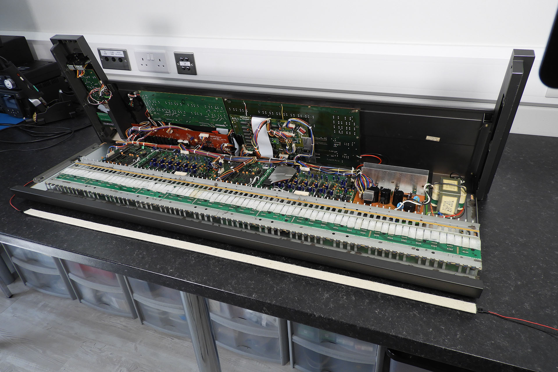
Of course, another interesting issue is that if I remember correctly, the D-50 was the first Roland Synthesiser to have everything, including the keyboard chassis, secured to the inside of the top-case. Unscrew the bottom case and you're in and there's nothing bolted to it.
Roland D-50 with the new 'upside-down' assembly. In I guess in comparison to building half the synth on a piece of wood and then connected to it the other half which was built into metal / plastic, this approach saved a lot of manufacturing time in 1987.
This aspect of the project presented some challenges which made me consider that the AT-D-50 might be my first FSR-based replacement aftertouch system that would be supplied in kit form. Here's why...
Just about every keyboard that features aftertouch and that I've worked on, has a small notch cut into the keyboard side of each end-cheek, just underneath the key-line, which allows for a margin of error in the length of the sensor. I take full advantage of this notch as however hard I try, I cannot cater for extremes of assembly / construction tolerances in a machine that's almost forty years old.
While the D-50 and similarly constructed synthesisers, also have this notch, it's quite small and things can be tight.
Note the notch cut into the inside of the left-hand end-cheek. There's one on the other side, too. They allow any excess aftertouch sensor to be neatly slipped out of the way. My sensors are a little wider than the original so I have to engineer things very precisely as I can't use this and I definitely don't expect customers to make this larger!
The idea of having to provide one of my aftertouch systems only in kit form didn't appeal to me at all. Many of my customers have a good degree of competence with electronics but the issues here were really mechanical. I didn't want to exert unnecessary pressure on those who already have a potentially challenging installation job ahead of them and so I had no option other that to persevere and find solutions to the problems.
Well, it took me a couple of weeks but I got there in the end. Once word of my replacement aftertouch sensor for the Roland D-50 got out, amazingly I had another D-50 come in which allowed me to confirm my measurements and installation procedure.
Similar to my other FSR-based aftertouch sensors, my AT-D-50 replacement aftertouch sensor for the Roland D-50 comprises two force sensitive resistors. The terminals of each sensor are passively connected on a little FSR Aftertouch Interface (FAI) PCB which is supplied with the AT-D-50.
FSR Aftertouch Interface (FAI) PCB combines the outputs of each FSR and provides a simple way to select one of two sensitivity ranges.
The output from the FSR combination is quite different to the original carbon-track based system that Roland used in the eighties. FAI compensates for that difference but also offers something else.
FAI provides the facility to select one of two sensitivity ranges. Yes, that's right! What a cool little feature. 🙂 On top of that, the aftertouch control next to the volume control on the top of the D-50 still works as it did before.
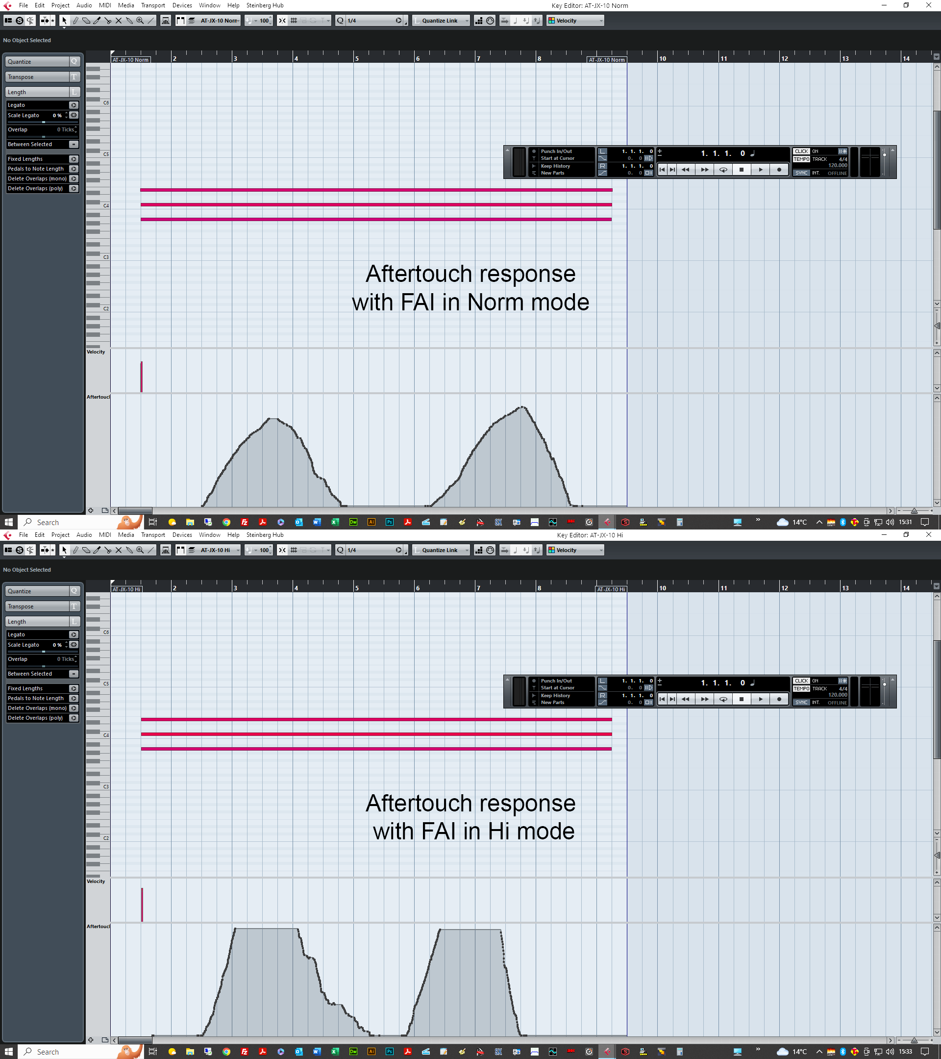
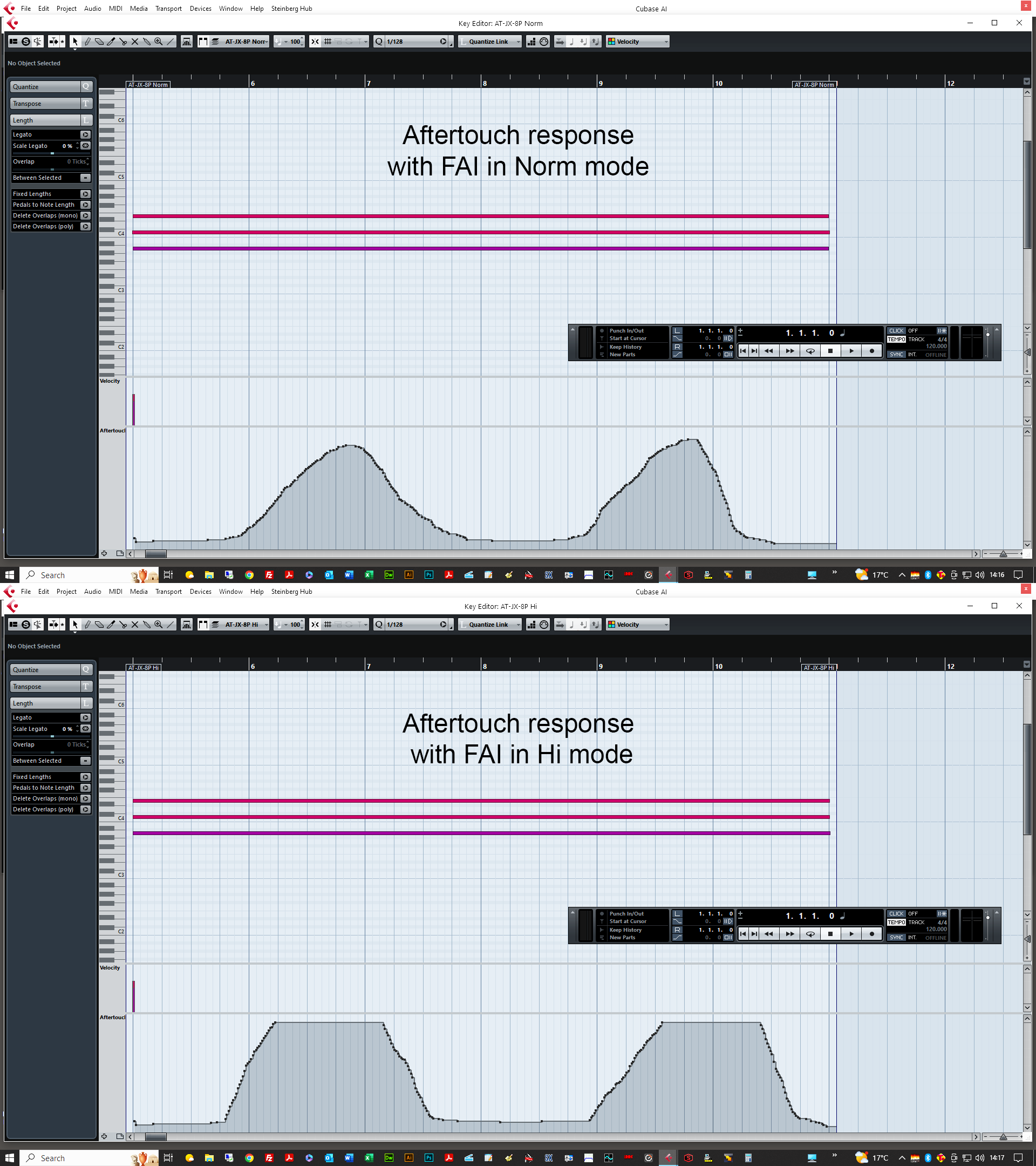
With the aftertouch fader on the D-50 set to about 80%, a MIDI velocity of about 90 and an average pressure, responses were recorded into Cubase with FAI in Norm and Hi modes. As you can see, a MIDI aftertouch value of 127 is reached in both modes. It's just that you get there quicker in hi mode.
Don't forget that you still have control over how aftertouch interacts with each sound within the patch settings.
FAI D-50 MIDI response in norm and hi modes
The 'upside-down' construction (as I call it) of the D-50, means that it's simply not practical to mount FAI to the bottom-case. With so little room on the inside of the top-case, FAI's four self-adhesive feet safely secure it to the inside of the D-50's left side-cheek. I've tried to make things as ergonomic as possible but of course the bottom-case has to be removed to access FAI. Positioning FAI on the inside left side-cheek however, does offer an excellent degree of access to FAI once you're in so switching aftertouch sensitivity ranges in the future, won't be too difficult.
FAI for the D-50 required a redesign of previous versions. Being side-mounted, I decided to use straight (vertical) Molex connectors, for example. It just makes life easier.
Also, up until FAI D-50, the facility to switch between two aftertouch sensitivity ranges was done by changing the value of the feedback resistor in the aftertouch buffer op-amp circuit. In FAI D-50 however, I decided to do the same job by switching the value of the series resistor between the FSRs and the op-amp.
Remember I mentioned earlier that the D-50 has a lot of passive SMDs? Well one big bonus of adjusting aftertouch gain by varying the series resistor to the buffer op-amp, is that no components on the bender-board need to be replaced. In fact, the bender-board doesn't even need to be removed. All you need to do is solder a two wires to the bender-board.
The bender-board in the D-50 is packed with SMDs. FAI D-50 uniquely delivers the option of switchable aftertouch sensitivity ranges, without you having to touch them!
You've developed an FSR-based aftertouch sensor for one synth (in fact, three) and you think it would be easy to knock up an FSR-based aftertouch sensor for another. Hmmm... not quite. Each synthesiser has it's own challenges and I'm so glad I persevered with this project. I'm delighted that AT-D-50 not just works brilliantly but is now a system which can be installed by anyone with a little patience and technical competence.
With an abundance of sensitivity and very high dynamic range, my replacement aftertouch sensor for the Roland D-50 truly gives this classic synthesiser, a whole new lease of life. It's like suddenly having velocity sensitivity! 😀 The added expression is just magical.
Modern FSRs are very reliable and it's not uncommon to see specifications quoting figures such as 'more than 10,000,000 actuations'. Being sealed units, FSRs are vulnerable to contaminants and oxidation problems like the old carbon-track sensors. It's no surprise then, that modern instruments that feature aftertouch, use FSRs. As previously mentioned, FSRs have a much greater dynamic range than their carbon-track counterparts which makes them ideal for modern drum pads.
I sometimes get asked to provide audio samples but I've backed off from doing that. Aftertouch isn't a sound, it's the result of a feel. You don't 'hear' aftertouch. You hear the effect of aftertouch. So posting an audio file with no reference to how the synthesiser was played, just seems a bit pointless to me. What I can tell you, is that the feedback I've had from users who have installed my FSR systems is humbling and inspiring. For a couple of hundred bucks, it's really worth a shot.
PACKAGING
The AT-D-50 is sent out complete and in one straight piece. Although it weighs very little, the external double-sided carboard box is just under 1.2m long. Using normal courier methods worked out to be horrendously expensive and so I engaged the services of a shipping agent.
Packaging the ATD-50 starts with sandwiching it in between two pieces of hardboard. The wires are then neatly folded and secured to the hardboard with masking tape.
It's important that the sensor is kept straight so I sandwich it in between two pieces of hardboard.
To keep any moisture off the sensor during transport, the package is then put into a long polythene bag.
A polythene bag is then used to reduce the potential ingress of moisture and damp during its travels. FAI and any other bits are put into an electrostatic bag and then into a small bubble-wrap bag.
The protected sensor is then packed into a double-sided cardboard box and wrapped in black pallet-wrap which gives the package a little security and added protection against damp and moisture.
Being able to convey feel to the sound after the keys are played, can transform a performance into something quite unique and almost magical. Indeed, Roland was definitely on to something when aftertouch began appearing on it’s synthesisers in the mid-eighties. Today, many classic synthesisers have aftertouch strips that either don’t work or are a shadow of what they used to be. Almost forty years later, my Roland Alpha Juno 2 replacement aftertouch sensor which uses modern FSR technology, has considerably more dynamic range and is infinitely more reliable than the second-generation transducers that Roland originally used in the AJ-2 and transcends the instrument into another dimension.
A couple of months ago, I received two Roland JX-8Ps with amongst other issues, failed aftertouch sensors. It was a great opportunity for me to try out something I've been meaning to do for a few years now. In no time, I'd developed a force sensitive resistor (FSR) based aftertouch system for the JX-8P. My friend Guy Wilkinson then lent me his JX-10 and 'AT-JX-10' appeared a couple of weeks later. After launching these products, something unexpected happened; I got contacted by a few AJ2 owners asking if I had considered developing a Roland Alpha Juno 2 replacement aftertouch sensor. Well, I hadn't but hey, here it is! 🙂
Roland launched the Alpha Juno 2 a year or so before I joined the company in '86 / '87 but like most music tech' at the time, instruments like the MKS-80, Juno-106, JX-8P and JX-10 were the ones that seemed to pop my eyes. As such, I never paid much attention to the Alpha Junos until many years after I'd left the company.
Today, the Alpha Juno 2 is a much respected synthesiser which has also proved to be very reliable... apart from the aftertouch. It was kind of a no-brainer therefore, to sort this out, especially following on from the success I'd recently had with the JX-8P and JX-10 replacement aftertouch sensor projects. There was only one problem; I didn't have a Roland Alpha Juno 2. 🙁
The development costs of designing peripherals for vintage equipment can be considerable and I was reluctant in this case, to whack on a good sum for a second-hand AJ-2. Having said that, I very almost did. But then...
Jumping to the rescue, my friend Guy Wilkinson suggested he contact a friend of his, who's an Alpha Juno 2 owner and indeed Jonathan was only too happy for me to use one of his his synths as a test bed. Yes, Jonathan has two Alpha Juno 2s!
So now I had a Roland Alpha Juno 2 but...
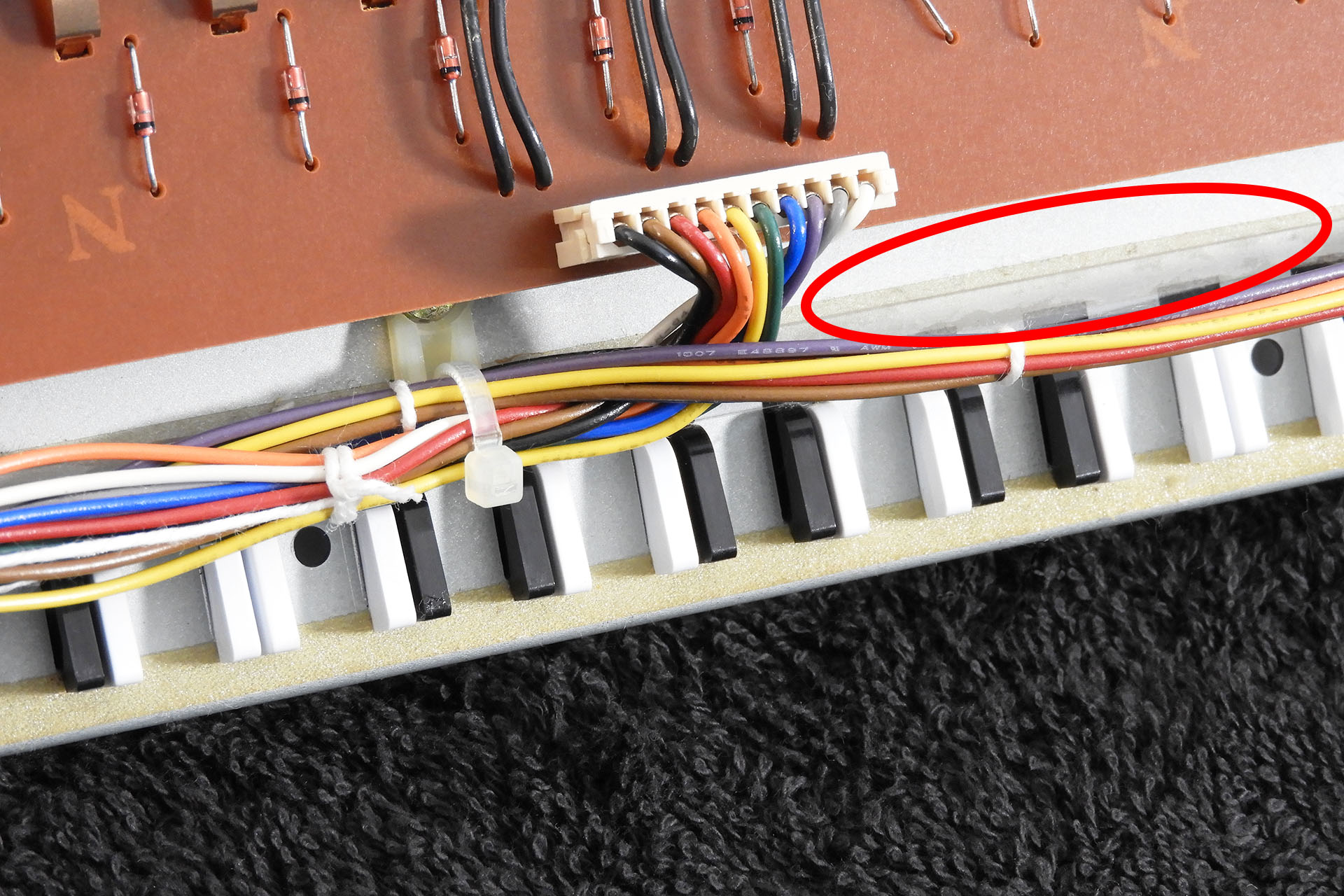
You need to be careful when taking apart an Alpha Juno 2 because the front of the main-board isn't simply screwed to any part of the chassis. Instead, Roland decided to have it supported in slots underneath the keyboard chassis. Removing the keyboard chassis without knowing this and hence, taking precautions, could easily snap the main-board! 🙁
Here's the underside of the AJ-2's keyboard chassis. Highlighted are slots that the front of the main-board slide into.
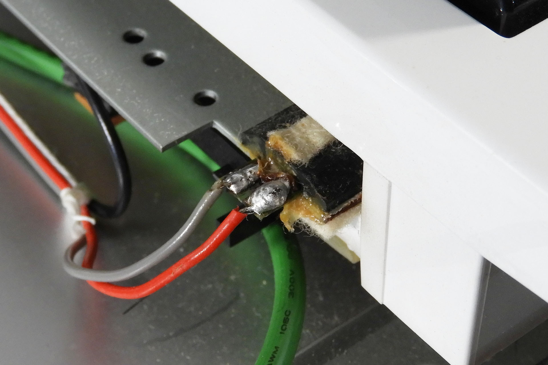
The original aftertouch strip looks kinda FSRish but it's not. Similar to the sensor found in other synthesisers at the time, it's simply a couple of plastic strips with carbon tracks sandwiched together.
The original aftertouch sensor looks pretty hi-tec for the mid-eighties.
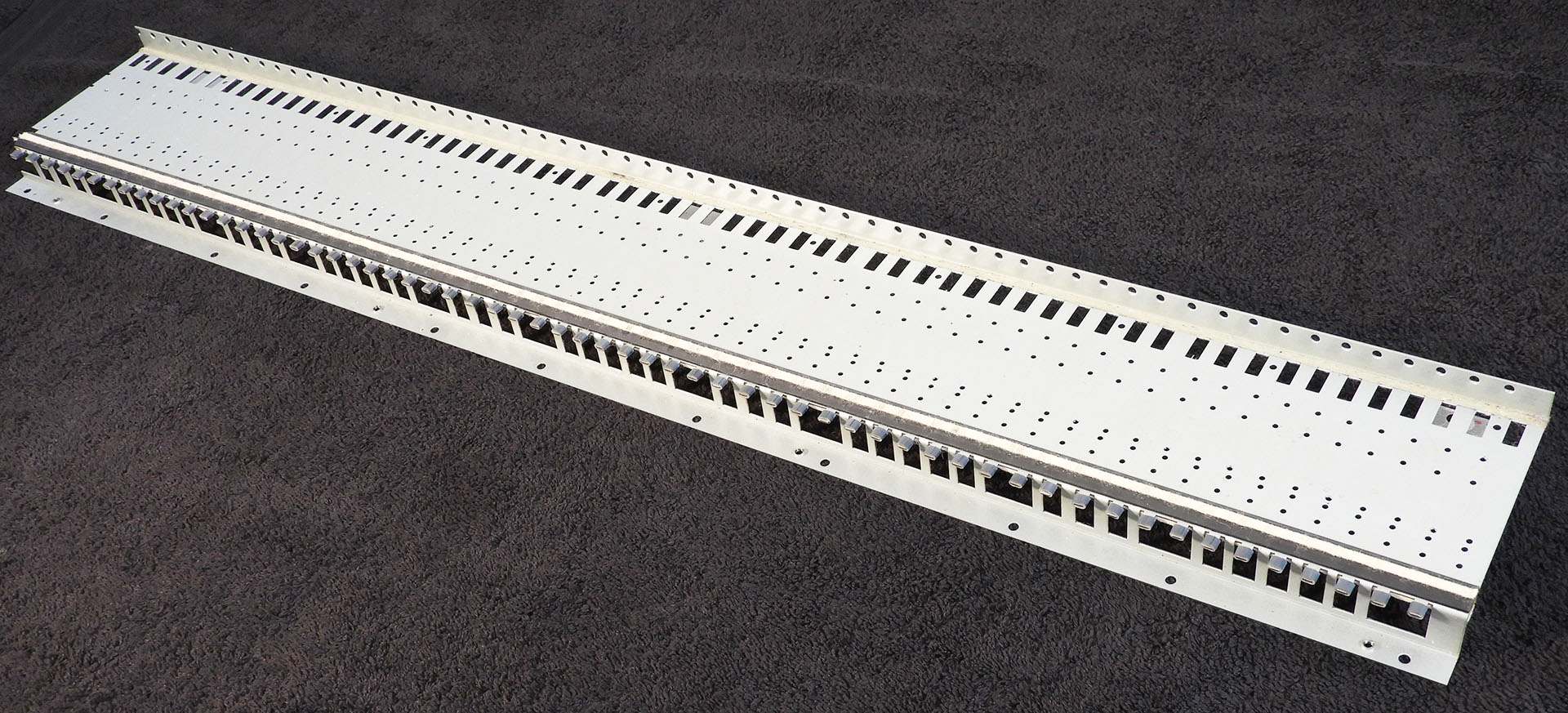
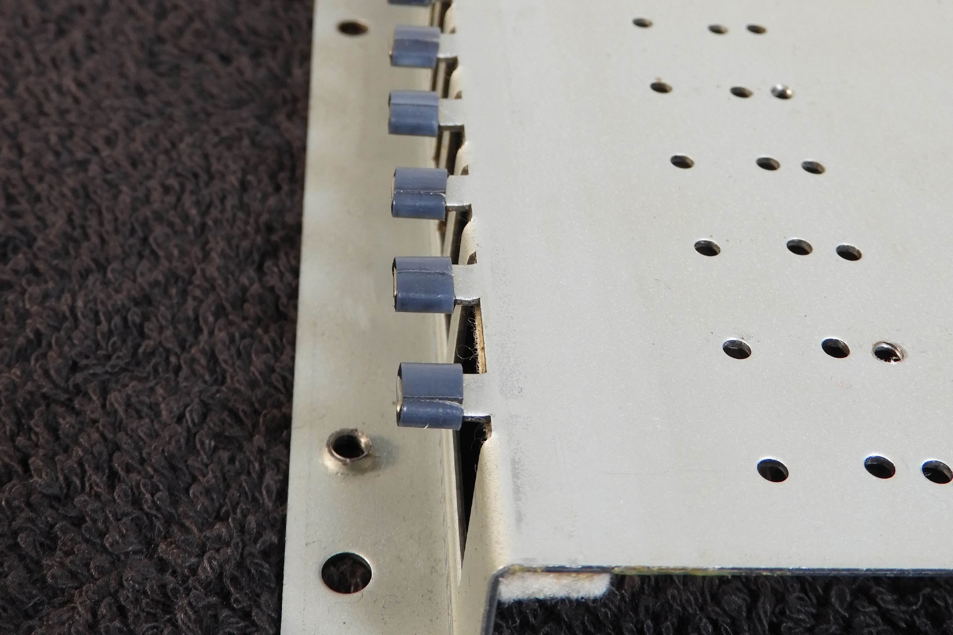
The Alpha Juno 2 is a slim instrument and wherever you look, space is limited. Even the front of the keyboard chassis is narrow. My replacement aftertouch sensor for the Roland AJ2 is 20mm wide and I just got lucky that it fitted.
Not much space for a replacement aftertouch sensor on the Roland AJ-2.
Being basically refined versions of the type of carbon-track sensors that Roland originally used but delivering a lot more dynamic range as well as other benefits, FSRs are perfect for this kind of application. In fact, modern aftertouch sensors and even some drum pads use FSRs. The principle is the same but the resistive polymer material is of a modern composition and the manufacturing process makes FSRs considerably more robust and reliable than previous pressure sensors.
Cross-section of a force sensitive resistor (FSR) illustrating how they work.
Having done this twice already and very recently and being very familiar with this synthesiser, developing a replacement aftertouch sensor for the Roland Alpha Juno 2 mainly involved measuring up and fine-tuning my FSR Aftertouch Interface (FAI) PCB.
My FSR Aftertouch Interface (FAI) PCB has a cool little secret on-board; switchable aftertouch sensitivity ranges!
What I mean by 'fine-tuning' is that FAI provides the facility to switch aftertouch sensitivity ranges (what a cool little feature). By simply moving a jumper on FAI, you can select between 'Norm' or 'Hi' sensitivity. Hence, I need to play around with some resistor values until things feel right in both modes.
Below you can clearly see the difference between the the two modes. In Norm mode, aftertouch responds smoothly but requires more finger pressure to reach full scale deflection (MIDI value 127). In Hi mode however, aftertouch gets to full scale deflection a little quicker and of course, requires less finger pressure to achieve this.
With hits of around MIDI velocity 95 and subsequent average finger pressure, you can see the difference between FAI's Norm and Hi modes.
In the AJ-2, aftertouch can be assigned to DCO, VCF or VCA and you have scope for further adjustment of the affect of aftertouch on the respective parameter.
Like all of my replacement aftertouch sensors, the AT-AJ-2 employs two FSRs and it's not practical to simply connect them to the original aftertouch wires and so FAI also makes life easy by passively combining the signals off the FSRs.
Although quite small, again with limited space inside the chassis, the positioning of FAI had to be carefully considered. FAI couldn't go behind the pitch-bend assembly like my AT-JX-8P and AT-JX-10 installations.
FAI mounted close to the main-board and not behind the pitch-bend assembly as with other FSR-based aftertouch systems I've done.
Different to previous FSR-based aftertouch projects, designing and installing my AT-AJ-2 presented some unique and interesting challenges. It wasn't quite the 'walk-in-the-park' I thought it would be, that's for sure. The Alpha Juno 2 was for example, particularly fussy about the height of its aftertouch strip. Having already designed a couple of FSR-based replacement aftertouch sensors, the height of the whole sensor assembly is of course, one aspect I pay a lot of attention to. If the sensor is too high, when a note is pressed, contact with the second carbon nipple in the contact bubble might not happen and you'll get no sound. If the sensor assembly is too low, you'll potentially wear out the key contacts quicker. Seriously, a fraction of a millimetre can make a significant difference.
Wanting this system to be available to all AJ-2 owners however, meant that not only did I have to overcome these challenges but I had to do so in a way that any technically competent person could easily follow. Operating on vintage synthesisers requires patience and an appreciation of how the manufacturer did things back in the day. You can't just take things for granted!
"So what does my Roland Alpha Juno 2 replacement aftertouch sensor sound like?"
Well, that's actually the wrong question! With a dynamic range that's quite literally in a different league to the second-generation transducer that Roland used in the Alpha Juno 2, my AT-AJ-2 feels just magic! The new system delivers a conversion of human touch to sonic expression that is perhaps what Roland had in mind in the mid-eighties but was unable to realise at the time.
If you want to know more about the fabulous Roland Alpha Junos, then you might find this interesting reading.
If you just want to buy my AT-AJ-2 replacement aftertouch sensor for the Roland Alpha Juno 2, you can do so here...
UPDATE - 10th July 2023
Yesterday my friend Guy Wilkinson came to see me to collect Johnathan's Alpha Juno 2 and to catch up about a whole bunch of other stuff. Not knowing too many people who speak my language, it's great having Guy over. When we meet up, it kind of gets a bit geeky 😀 but it's so much fun!
Anyway, Guy messaged me later in the evening with a link to his home page. Here's what he had to say:
"Repeat 9th July 2023: Alex did it again for the Alpha Juno 2, such a sublime upgrade because the synth is such a lovely sounding and traditional polysynth (less is more)……a great Aftertouch performance really makes it shine expressively. I have spent a lot of time with it, enjoying the synth in a new way. Shame I have to hand it back 😁
If you are interested in one of these fabulous kits with an extremely long life modern sensor, then check out Alex’s site pages: JX-10 , JX-8P & Alpha Juno 2.
Bring the expression back into your Vintage synthesizer."
Thank you for your kind words, Guy.
A special T H A N K Y O U to Jonathan W for lending me his Roland Alpha Juno 2.
PACKAGING
The AT-AJ-2 is sent out complete and in one straight piece. Although it weighs very little, the external double-sided carboard box is just under 1.2m long. Using normal courier methods worked out to be horrendously expensive and so I engaged the services of a shipping agent.
Packaging the AT-AJ-2 starts with sandwiching it in between two pieces of hardboard. The wires are then neatly folded and secured to the hardboard with masking tape.
It's important that the sensor is kept straight so I sandwich it in between two pieces of hardboard.
To keep any moisture off the sensor during transport, the package is then put into a long polythene bag.
A polythene bag is then used to reduce the potential ingress of moisture and damp during its travels. FAI and any other bits are put into an electrostatic bag and then into a small bubble-wrap bag.
The protected sensor is then packed into a double-sided cardboard box and wrapped in black pallet-wrap which gives the package a little security and added protection against damp and moisture.
Final external packaging is pretty robust!
UPDATE - 28th July 2023
My AT-D-50 FSR-based replacement aftertouch sensor for the D-50 is a go! You can read all about here.
I'm sorry to say this but I'm not exactly a big fan of modern guitar amps! 🙁 So sorry but I think there's far too much stuff going on for something that should in essence, be quite simple with the important stuff being well... seemingly, not so important! The fact that I had to do this EVH 5153 Mk3 screen grid circuit rebuild kinda says it all.
This amp came to me because it was blowing fuses. The power valves were fried but it didn't look like 'normal' wear was responsible so I decided to open up the amp.
Unfortunately, I didn't take any pictures of this prior to changing components. The image below however, will give you an idea of where the power amp circuit board is (top right). On the other side of this small PCB is a pair of 6L6 valves.
The schematic marks resistors R139, R140 and R157 as 'fp' meaning 'flame proof' which is rather ironic as they were burnt out!
EVH 5153 Mk III Schematic with crucial screen grid components highlighted in red and cathode to ground and V8 plate components shown in blue.
The reason that R139 and R140 failed so dramatically is because of a valve going short-circuit. As this condition occurs, more current is pulled from the screen grid supply. This has the effect of heating up the screen grid resistors, eventually exceeding their power rating and so they blow. It's actually a safety feature to protect more expensive parts of the amp like the output transformer.
There's a temptation to uprate the resistors to say 2W or even 5W but this isn't a good idea. If the same thing happens again, there's a chance of doing some serious damage. What I did do, was stand the replacements further off the PCB.
R157 is interesting. In many amps, this resistor doesn't exist and the connection is a short. In this amp, R157 looks like it's also there to protect the amp. Similar to a fuse, a 1Ω resistor in this position (between the valve cathodes and ground), helps protect the output stage of the amp, in the event of a valve failure, just like the screen grid resistors. The current flowing through the resistor is less than 50mA and substituting the original component with one of a higher power rating would negate this cool little safety feature. Hence, I decided to drop in a similar 1Ω / 1W device.
The schematic doesn't specify the tolerance of R157 but here's why I chose a high tolerance substitute:
A high tolerance 1Ω resistor (say 1%) in place of R157, also makes bias current measurements easier. Whilst not mentioned on the technical literature, you can clearly see that 'BIAS' is actually written on the PCB next to R157. By measuring the voltage drop across the resistor and then using Ohm's law (V = I x R), it's easy to suss out the bias current. Since R = 1, the current will be the voltage that's read across R157 because I = V / R or I = V / 1).
D29 was also fried. This diode is a plate diode for one of the valves. It may have burnt out because R157 which sits right next to it, overheated or because V8 started pulling more current due to the failing screen grid resistors. Now that the screen grid resistors have been changed however, I think this'll be okay with a standard 1N4006 direct replacement.
If you have one of these amps and are considering a similar EVH 5153 Mk3 screen grid circuit rebuild, please take all precautions. Valves amps bite!
Highlighted in red are uprated screen grid resistors. Highlighted in blue are replaced 1Ω resistor R157 in cathode circuit and 1N4006 (D29) plate diode of V8.
It's difficult to buy a newer amp that doesn't have a printed circuit board (PCB) but I feel that designers need to take care.
While currents are low, valve amps have hundreds of volts all over the place and to route these voltages on PCB tracking worries me a little, especially when the layout is pushed for space. High-voltage carrying tracks often end up being very close to other tracks which in my humble opinion, isn't good.
If we take a closer look at this 5153 Mk III for example, carrying several hundred volts, the track on the positive side of D29 (that's going to the plate of V8) really doesn't seem very substantial and on top of that, it seems a little too close for comfort, to the ground side of R157. 🙁
Welcome to my Galaxy! Initially a proof-of-concept, Galaxy ended up being the ultimate Behringer DEQ2496 replacement power supply!
Galaxy replacement power supply for the Behringer DEQ2496.
I’ve been a big fan of this processor since Behringer launched the 2U DSP8000 Ultracurve which soon evolved into the DSP8024 Ultracurve. It's no surprise therefore, that I'm currently using six Behringer DEQ2496 Ultracurve Pros in my studio. An excellent processor which in its current version, offers features and benefits such as
Compact 1U format
Ergonomic front-panel layout
Intuitive GUI on a large display
Simultaneous multi-function processing
Huge audio connection options, both analogue and digital
Professional interfaces including Word Clock
Excellent audio quality
Analogue true bypass
Internal memory
MIDI to allow remote control and saving of internal memory to a computer
Amazingly cost-effective solution
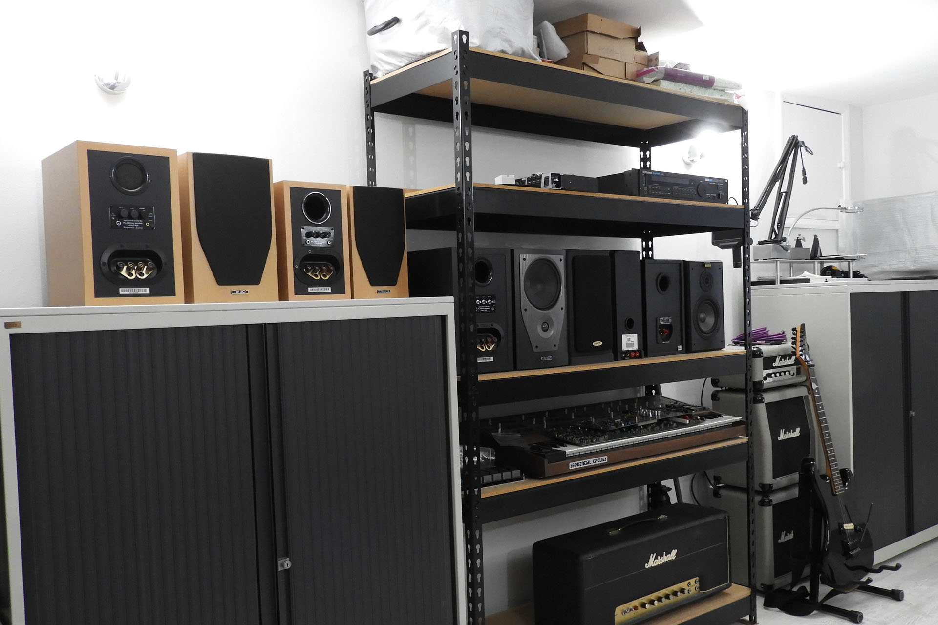
One of six Ultracurves in my studio together with another couple of Behringer 'Swiss army knife' type processors.
The Behringer DEQ2496 joins a selected few processors that can be found in recording studios, broadcast studios, night clubs, theatres, in the filed, audiophile set-ups and home theatre systems. That in itself is a big deal.
So why are we here? What’s wrong with the DEQ2496?
Well, nothing really but despite its huge feature list, the fact that at the time of writing, it’s still in production and retails for a very acceptable price, it does have one or two snaggy annoyances.
Made in the Far East, quality control used to be and sometimes still is an issue. Problems with internal cables for example, have been well documented. In fact, I’ve repaired a lot of Ultacurves over the years and indeed many have had simple inter-board connection issues.
Great but that’s still not why we’re here!
With thousands of Ultracurves across the world now getting quite old, many DEQ2496 power supplies are starting to fail. Symptoms are various ranging from erratic or unpredictable behaviour, to the DEQ2496 simply not switching on.
Yeah but hang on a second... is the power supply in the DEQ2496 actually a Behringer power supply?
Good question! Labelled as a Behringer Model PSU2496, it would appear that it's actually made by Eton, a well respected manufacturer of switched-mode power supplies and is from the ET166 range.
The Behringer PSU2496 power supply or is it an Eton ET166?
The PSU2496 is a very cleverly designed little power supply. Labelled as a switched-mode power supply (SMPS), it's actually a hybrid. The voltage for the +/-15V analogue supplies for example, comes off a pair of 78 / 79 series regulators. The input to those regulators however, does come from a very fast-switching back-end. It's a trick I've used myself, to make guitar pedal power supplies and it works really quite well. Using LDO regulators on the back-end of a SMPS is an excellent way to reduce EMC and ripple but is expensive for manufacturers to implement.
The Behringer PSU2496 uses linear voltage regulators for+/-15V audio supplies.
The PSU2496 is packed with a bunch of similarly neat little features including proper capacitive ground / earth decoupling which I have incorporated into the Galaxy design.
From my experience, these things don't fail because of poor design, sub-standard components or build quality. They fail because they're old. A lot of heat is generated by the power supply and devices will eventually succumb to thermal stress. It's that simple. When it comes to current provision, it's difficult to tell what margins exist between the PSU2496 rated currents and what the DEQ2496 pulls off each supply. One could argue that the reason the PSU2496 runs so hot is because there isn't much margin at all and that the power supply is actually running near to the edge of its limits.
In the event of PSU failure, swapping out the through-hole electrolytic capacitors for high-temperature rated, low ESD equivalents, can help but sometimes other components fail and fault-finding a switched-mode power supply can be quite challenging, even with the appropriate technical literature. The wire-wound components are of particular concern as it's virtually impossible to acquire these as spare parts.
The original Eton power supply is compact and light. The mounting bracket doubles up as a very much needed heatsink. When designing Galaxy, the huge amount of redundant space was a real bonus. Note, that an insulating boot has already been put on the IEC C14 connector.
Initially a proof-of-concept, my Behringer DEQ2496 replacement power supply wasn’t intended to become a commercial product. Once it was up and running, installed in two of my own Ultracurves and having worked flawlessly for a couple of months, I mentioned the project to some friends and customers who I knew were DEQ2496 owners. Within a couple of weeks, three customers had brought me their Ultracurves asking if I could install my Behringer DEQ2496 replacement power supply. That’s when things started to get serious and Galaxy was born.
Using the same mounting points as the original PSU (and a couple of PCB stand-offs), Galaxy fits like a glove.
Had I designed a power supply similar to the Behringer PSU2496 (or Eton ET166), I don't think I'd have come up with anything much better, to be honest. As I've already commented, it's actually a good power supply! Anyway, fortunately there's enough room in the DEQ2496 case to develop something a little special and what this awesome processor really deserves.
Galaxy is also a SMPS but with several differences to the Behringer PSU2496.
Unlike the PSU2496 with all its interdependencies, Galaxy offers fully independent voltage supplies, with only pre-filtered mains, common to all.
Using low-leakage AC / DC converters which are both over-voltage and over-current protected, the heat generated is much, much lower than the original PSU2496. During tests, I measured the temperatures of the converters an hour after power-up and with the top-case on. The hottest measured only 38°C. To put things into perspective, one of the processors was about 42°C. It's quite reassuring that Galaxy is running cool and not significantly contributing to the heat build-up inside the Ultracurve as was its predecessor.
I wanted Galaxy to be an easy installation, something that anyone with a little technical competence could achieve. Indeed, other than the potential rewiring of the IEC connector, Galaxy is a solderless upgrade.
Switched-mode power supplies shouldn't generate hum like linear power supplies. Due to the nature of operation however, they can / do generate very high-frequency noise. When designing switched-mode power supplies intended for use in audio electronics, comprehensive noise filtering is paramount. To that end, Galaxy has precision-designed filters on the back-end of each AC / DC converter, including those that supply 5V and 3.3V for the digital side of things (something you don't see too often).
Galaxy has independent voltage supplies and each is individually filtered.
Each supply also has its own status LED giving a simple visual indication that respective supply lines are working.
Galaxy glows in the dark! Independent status LEDs show you that things are working. It's going to be bright in that box...
Voltages are directed to a rather over-sized 2.54mm (0.1 inch) pitch Molex KK 259 header and Galaxy is supplied with a connection cable to go to the Behringer DEQ2496 main-board.
7-way Molex to JST connector from Galaxy to DEQ2496 main-board is included with the kit.
Like all my modular switched-mode power supplies, there’s very little exposed mains voltage on the top-side of the PCB.
Galaxy has minimal exposed mains on the top-side of the PCB. There's no need to upgrade the Ultracurve's fuse and filtering ensures a clean and healthy AC mains is fed to the AC / DC converters.
In fact, safety always comes first so again in common with all my modular switched-mode power supply designs, Galaxy features a bleed resistor across the already fuse protected mains supply.
To reduce exposed mains on the top-side of the PCB, the bleed resistor is mounted underneath the board.
With safety still in mind, Galaxy is secured to the inside of the DEQ2496 chassis using the same mounting points as the original power supply. Stand-offs around the two connectors, reinforce the PCB and prevent the PCB from bending when connecting the mains supply from the switch and the connector from Galaxy to the main processor-board.
Galaxy uses the same mounting points as the original power supply and is very secure.
After measuring the current consumption of each voltage line, I wanted my Behringer replacement power supply for the DEQ2496 to have as much headroom as possible. One of my initial design objectives therefore, was that each voltage supply of Galaxy should be able to offer at least twice the current that is required. Taking advantage of the space available in the DEQ2496 case, I was able to fulfil that objective. Not stressed and with ample headroom, this is one reason why Galaxy runs so cool; the power supply can actually deliver considerably more power than is needed.
Galaxy uses high-specification, low-leakage, British made Vigortronix AC / DC converters with built-in over-current and over-voltage protection.
I'm so sorry to have to say this but one potentially big issue with Far Eastern manufactured equipment that's powered from mains, is the lack of standardisation, compliancy and safety of the power inlet. Quite frankly, it's all over the place. Live and neutral are often swapped around and it's very common for the power switch to be connected to the neutral line. This is really frustrating when it comes to confirming which line the fuse is in, for example.
"So what's the big deal?" I hear you ask.
Hey, don't take my word for it. The following was taken from some PAT testing guidance I found on line here.
Under normal circumstances, the current will go to the appliance down the live wire first passing through the plug fuse (and any internal fuse). If the appliance has a fault and draws too much current, the fuse would detect this and blow. If the live and neutral wires are crossed over, the current passes down the neutral first. The result is the equipment user could be at risk if the appliance has a fault.
I therefore include a couple of bits with Galaxy like an insulating boot that fits over the back of the IEC socket. I also recommend that while the box is open, you check the input mains polarity and correct it if it's wrong.
Galaxy includes a kit to help make the DEQ2496 a little safer. All required information is included in the installation manual.
Behringer has a well established reputation for making affordable audio gear. It doesn't always mean however, that quality needs to be compromised. The DEQ2496 Ultracurve Pro epitomises that fact. Competitively priced, it's difficult to find something similar. My Galaxy replacement power supply for the DEQ2496 will ensure that at least the power side of things will run smoothly and last for a very long time. 🙂
Replacement power supply for the Behringer DEQ2496 Ultracurve Pro.
Installing Galaxy is amazingly straight-forward for anyone who has experience with opening up 19-inch rack gear. Personally, I would check the polarity of the mains live / neutral, correct them if they're wrong and check that the ON / OFF switch is switching live and not neutral. Other than that, there's no desoldering / soldering, just four screws to remove, four replacement (longer) screws to fit, a couple of connectors to pull off the old PSU and main-board and then connect Galaxy.
UPDATE - 23rd July 2023
I’ve already mentioned that my Galaxy replacement power supply for the Behringer DEQ2496 was basically a proof-of-concept project so you can imagine my surprise when orders quickly began to match those of my other power supplies.
All of my power supplies are soak tested for twenty-four hours, prior to shipping but I’ve never been happy that I’ve only been able test them ‘off load’ which means that the respective PSUs haven't been subjected to a current demand, as they would be in real life.
On the other hand, it’s quite impractical to have original machines on which to test power supplies like Aurora for the Roland MKS-80, Supernova for the Roland Juno-106 and Guy Wilkinson’s P0004 for the Roland Super-JX and so on.
Well, that has all changed as my Galaxy project encouraged me to design a small test rig which now allows me to test all of my power supplies, with a load.
Each Galaxy undergoes basic Voltage testing under load on my universal power supply test rig.
After the basic voltage test, every Galaxy then spends twenty-four hours in my test Behringer DEQ2496 Ultracurve Pro, before it's shipped to the customer.
Galaxy is then tested for twenty-four hours in a real Behringer UltraCurve Pro, prior to shipping.
I'm deeply concerned about the environment and the exploitation of labour and so I always use local manufacturers in preference to the Far East, with the following in mind:
I can be confident that workers are treated fairly and earn a proper wage.
I can be confident of the standard of quality of each item that is delivered to me.
Communication is important and using local manufacturers, all correspondence is quick and understandable.
I believe in supporting the local economy.
I can be confident that the disposal of manufacturing waste is managed properly and in accordance with national and EU law.
Galaxy replacement power supply for the Behringer DEQ2496 is made in the UK.
Using local manufacturers isn’t the cheapest option but the above points are important to me. I hope that they’re important to you too.
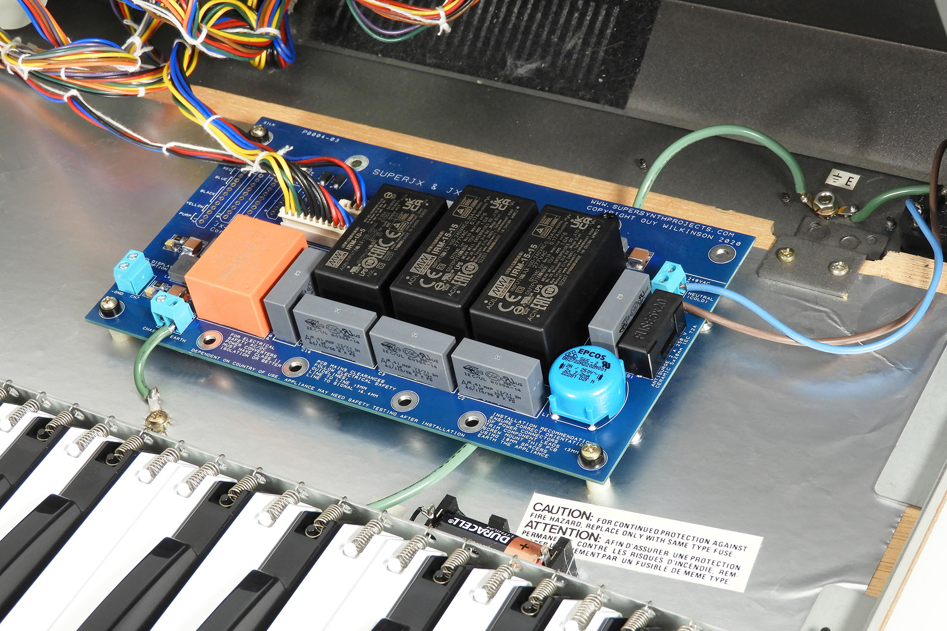
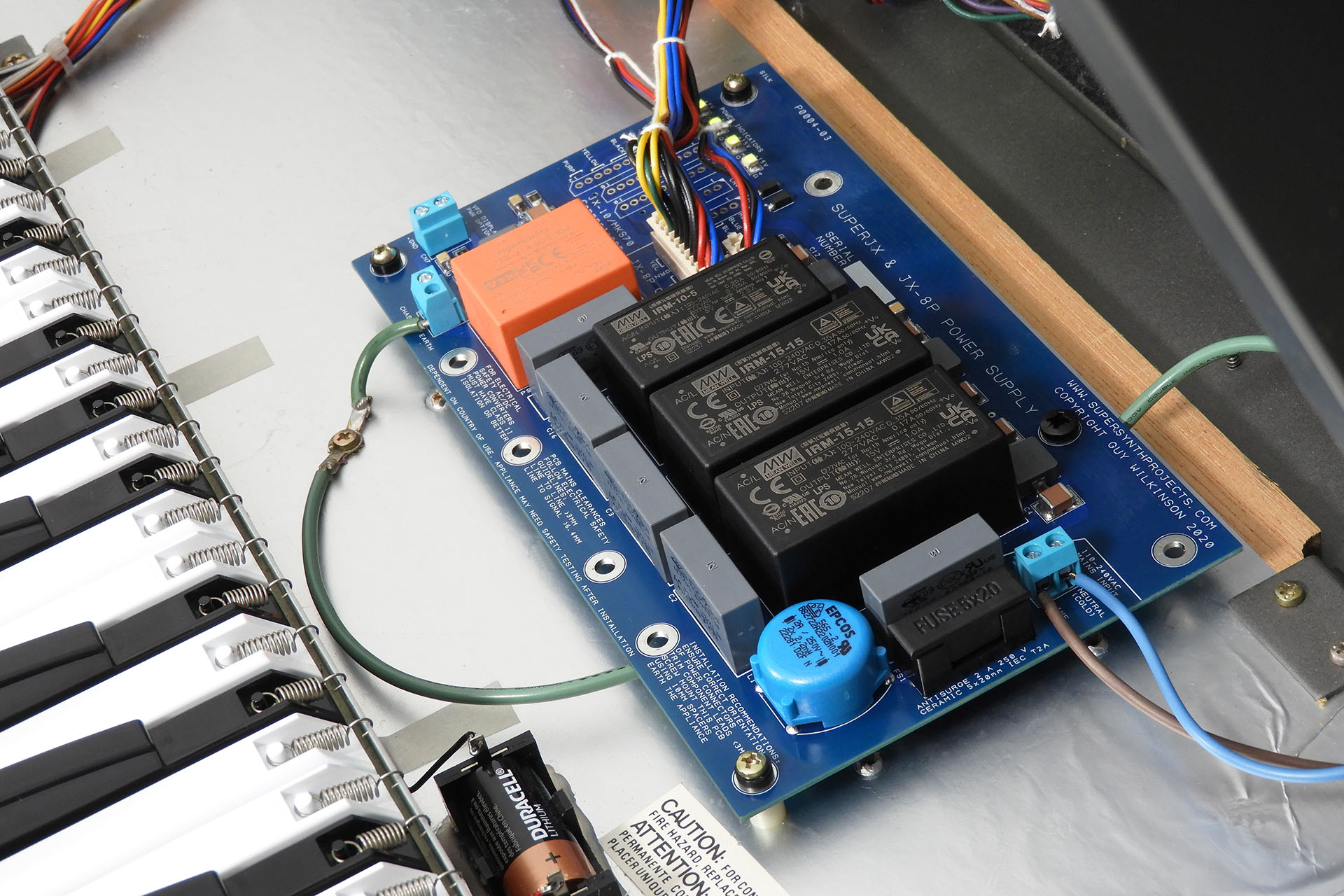
Guy Wilkinson's P0004 power supply is an established upgrade for many JX-10 and MKS-70 owners but few may be aware that it works just as well as a Roland JX-8P replacement power supply.
The P0004 runs cooler, is more efficient, more stable and considerably more reliable than an aging original Roland power supply.
Having worked for the company, I have to say that I've always been a fan of Roland's power supplies. People use the term 'unreliable' but the truth is that they've been working in thousands of instruments, for absolute decades. The problem is, how much longer can they last? 🙁
Vintage keyboards are now a collectable thing. Why would anyone risk a power supply failing and potentially bricking a gorgeous synthesiser?
Guy's well-designed and established P0004 addresses such concerns, as well as providing benefits such as universal power. Yes, that's right. The P0004 replacement power supply for the Roland JX-8P will work on virtually any mains voltage across the world. You don't have to switch transformer taps or use an external step up / down transformer, when moving your gear from one country / region to another.
At the back of the P0004 are four status LEDs which indicate active voltage lines.
In both images, you can make out that my Live Forever battery upgrade is also installed in this particular JX-8P. A smart little upgrade, you won't have to worry about losing your memory (?) or a leaking battery for a long, long time. 🙂 In fact, this JX-8P also has my AT-JX-8P replacement aftertouch sensor for the Roland JX-8P installed, giving it a whole new lease of life.
FSR-based replacement aftertouch sensor kit for the Roland JX-8P.
If you're having mains hum issues, the P0004 might fix things for you. The P0004 is a modular switched-mode design and doesn't generate hum like linear power supplies.
You can read more about my experiences with the P0004 here or check out Guy's website that's packed with loads of technical information here or... you can just buy it!
Being able to convey feel to the sound after the keys are played, can transform a performance into something quite unique and almost magical. Indeed, Roland was definitely on to something when aftertouch began appearing on it’s synthesisers in the mid-eighties. Today, many classic synthesisers have aftertouch strips that either don’t work or are a shadow of what they used to be. Almost forty years later, my modern FSR-based replacement aftertouch sensor for the Roland JX-10, has considerably more dynamic range and is infinitely more reliable than the second-generation transducers that Roland originally used in the JX-10 and transcends the instrument into another dimension.
Catching up one evening with my friend, Guy Wilkinson and on the back of my 'Replacement Aftertouch Sensor for the Roland JX-8P' project, it was a no-brainer to have a go at developing a similar, FSR-based, easy to install replacement aftertouch sensor for the Roland JX-10.
Guy's Roland JX-10 is immaculate!
Guy has a pristine JX-10 but the aftertouch was shot. I'm very aware that he's attempted several repairs but it just keeps on packing up. He told me that it kind of works but is either off or on and cannot produce a varying signal that's proportional to well, pressure. I was keen to see if I could help and like my JX-8P aftertouch project, possibly develop a replacement aftertouch sensor for the Roland JX-10, that anyone with a little technical competence could install.
So what the hell does 'FSR' stand for? What is a FSR?
Invented in 1985, force sensitive resistors didn't make it into mainstream music technology applications for a long time. The technology was just too expensive and even more so in custom shapes and sizes. FSRs would often require end-user assembly which increased production times and failure rates.
Cross-section of a force sensitive resistor (FSR) illustrating how they work.
Being basically refined versions of the type of carbon-track sensors that Roland originally used but delivering a lot more dynamic range as well as other benefits, FSRs are perfect for this kind of application. In fact, modern aftertouch sensors and even some drum pads use FSRs. The principle is the same but the resistive polymer material is of a modern composition and the manufacturing process makes FSRs considerably more robust and reliable than previous pressure sensors.
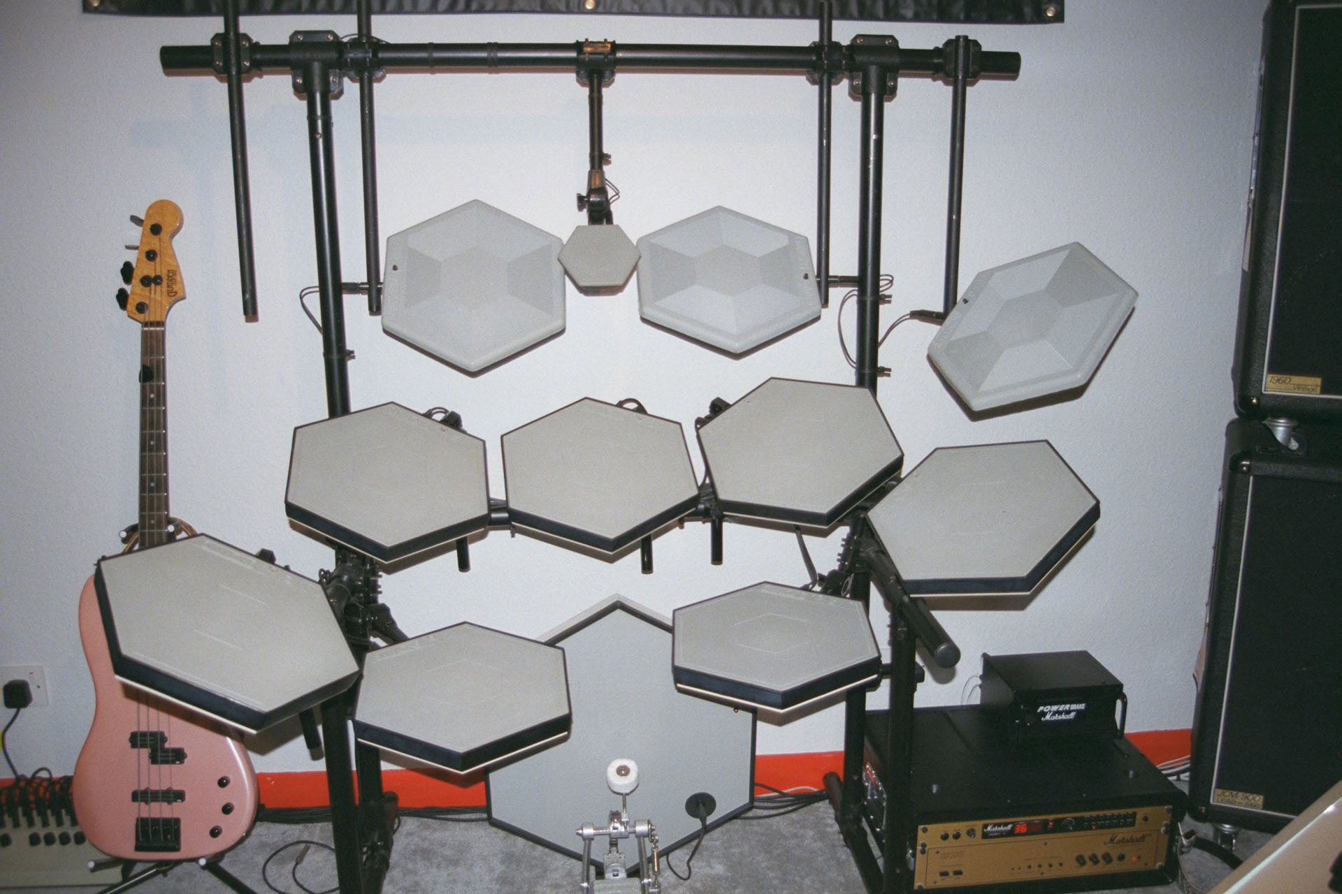
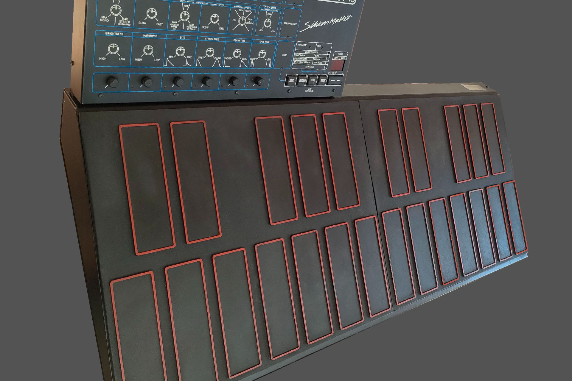
When I was at Simmons Electronics, we developed the Silicon Mallet and later, the SDX, both of which used FSR technology to trigger sounds, MIDI, etc. The SDX soon became famous for its zone intelligent (ZI) pads, for example. At a cost of about 13,000 GBP in 1987 for the basic model, go figure!
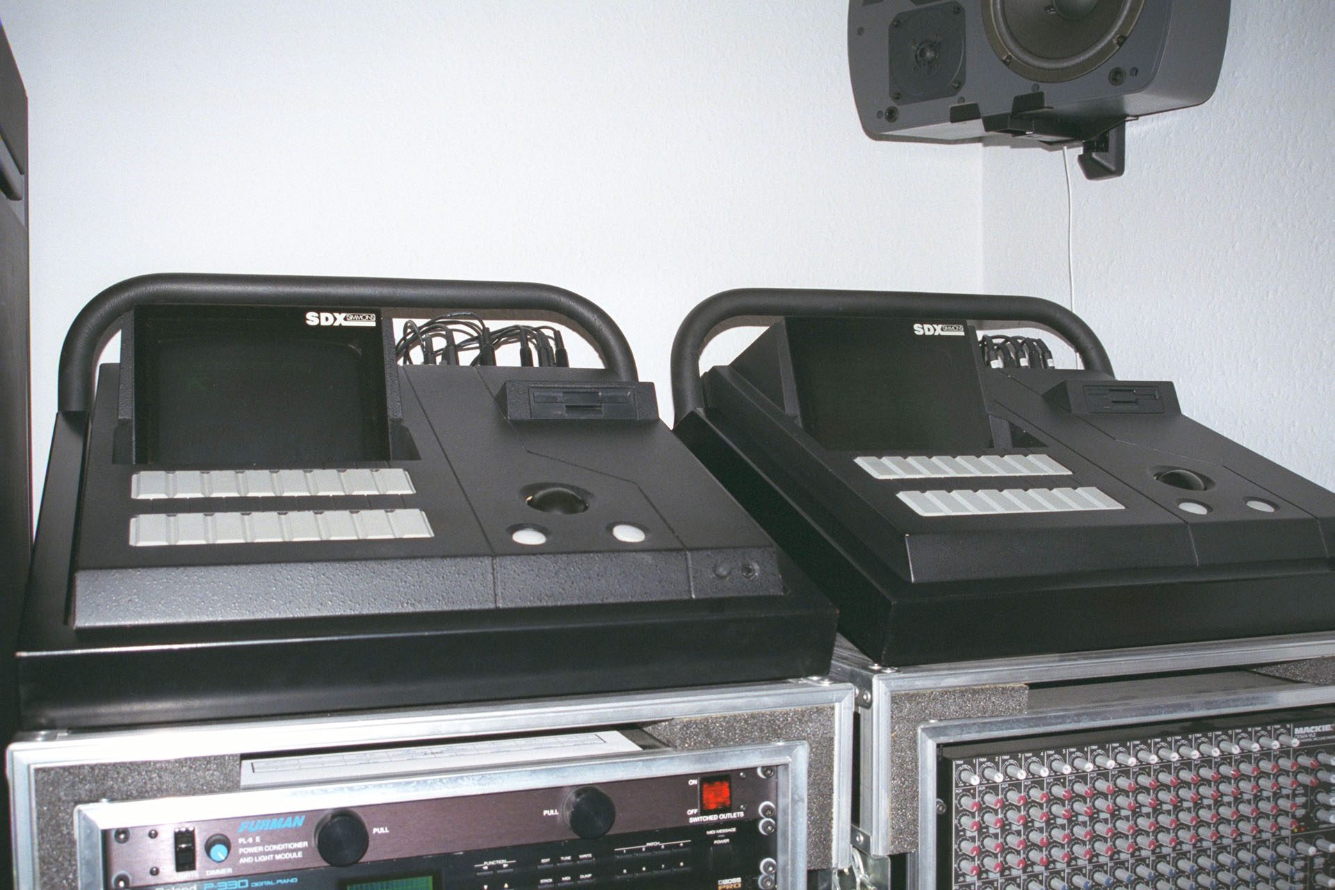
Here's an old snap of my 'small' kit. This expanded to double-kick, a few SDX ZI cymbals and a lot more toms.And here are my two Simmons SDX consoles from many years ago, in a previous studio (life). I still have them and hope I can get them back into my current studio soon.
Today, FSRs are used extensively for aftertouch and electronic drum pads so I've been meaning to try them out to fix aftertouch issues on vintage instruments for a long time. After motivating success on the JX-8P, I turned my attention to developing a replacement aftertouch sensor for the Roland JX-10.
Unlike the JX-8P, the JX-10 used a much simpler, twin carbon-track bottom contact membrane and a similar but single carbon track top membrane. The whole thing is much thinner than the JX-8P aftertouch sensor assembly but despite the use of carbon as opposed to copper (like in the JX-8P), the tracks were still quite exposed and vulnerable to the ingress of contaminants as well as wear.
After several decades the original Roland aftertouch sensor is, well... do I have to say it?
Having installed my replacement FSR-based aftertouch sensor into several JX-8Ps now, I knew that the implementation of the technology worked just fine on these vintage instruments. Often described as two JX-8Ps in one, it's no surprise that there are many similarities between the JX-8P and the JX-10. In fact, it's quite intriguing just how Roland can be seen to apply its experience, learning from previous instruments, implementing the latest technologies and yet keeping all the good stuff that worked well. I guess in the natural world, that's called evolution!
So, with very similar technologies and construction, there wasn't too much new to suss out. The real challenge with the JX-10 however, was physical. The height of the sensor assembly might have been an initial issue, for example. At between 2mm and 3mm, it was about half the height of the sensor in the JX-8P.
The original JX-10 aftertouch sensor is much lower than that in the JX-8P.
The second issue was limited width. The JX-10 used the familiar rubber bubble key contacts secured to a PCB which sits on top of the JX-10 keyboard chassis. The distance between the front of this PCB and the front of the keyboard chassis was only 21mm so I had no choice other than to use a narrower rubber strip over the FSRs, than I did on the AT-JX-8P aftertouch sensor project.
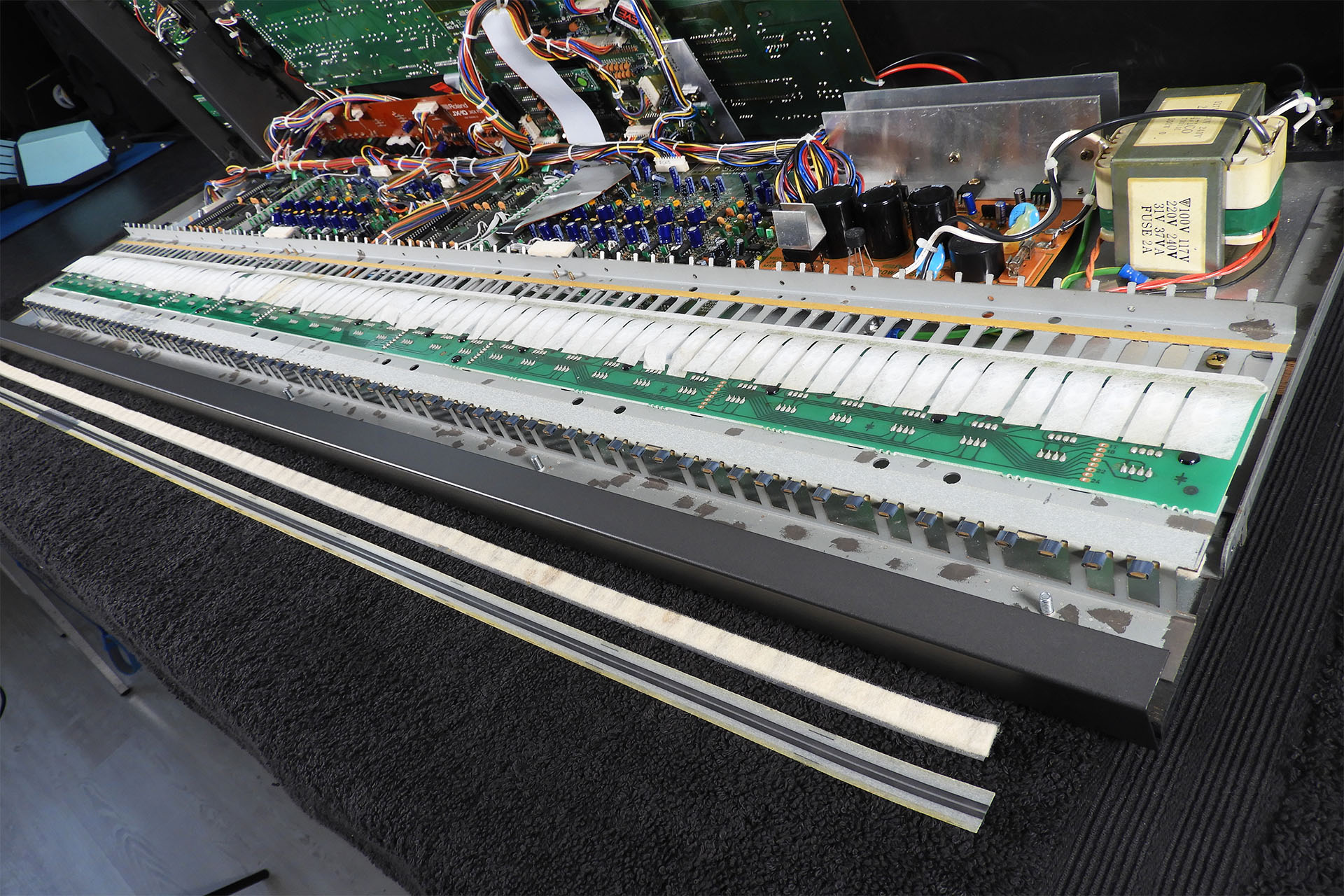
So, first things first. When developing the project for the JX-8P, I removed and stripped the entire keyboard chassis so that I could completely clean all traces of almost forty-year old glue! I figured I'd have to do something similar with the JX-10 and if so, that would require removing the two voice-boards, to get at the rear screws that secure the keyboard chassis. Oh BUM!!!! 🙁
Reluctant to take apart Guy's lovely JX-10 just to remove and clean off the remains of the bottom tracks of the original aftertouch strip, I thought I'd have a go with keeping the keyboard assembly in situ.
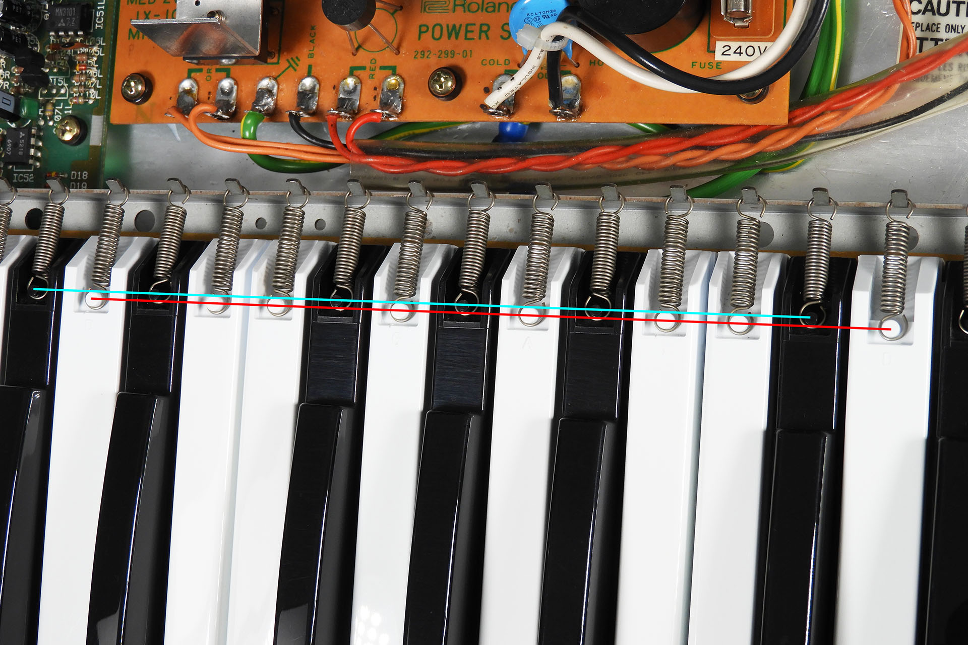
Knowing that the key tension springs for white keys are of a different length to those on the black keys, I removed the springs for the white keys first and grouped them together, before doing the same with the black keys.
Black and white keys have different length key tension springs on the Roland JX-10.
With a little trick, removing the keys can be done without removing the transparent plastic key retainer that sits underneath and at the back of the keyboard. All you have to do is gently poke down with a small screwdriver at the key locator at the back of each key, thereby pushing the key retainer down. The keys can then be gently pulled forward and off the keyboard chassis.
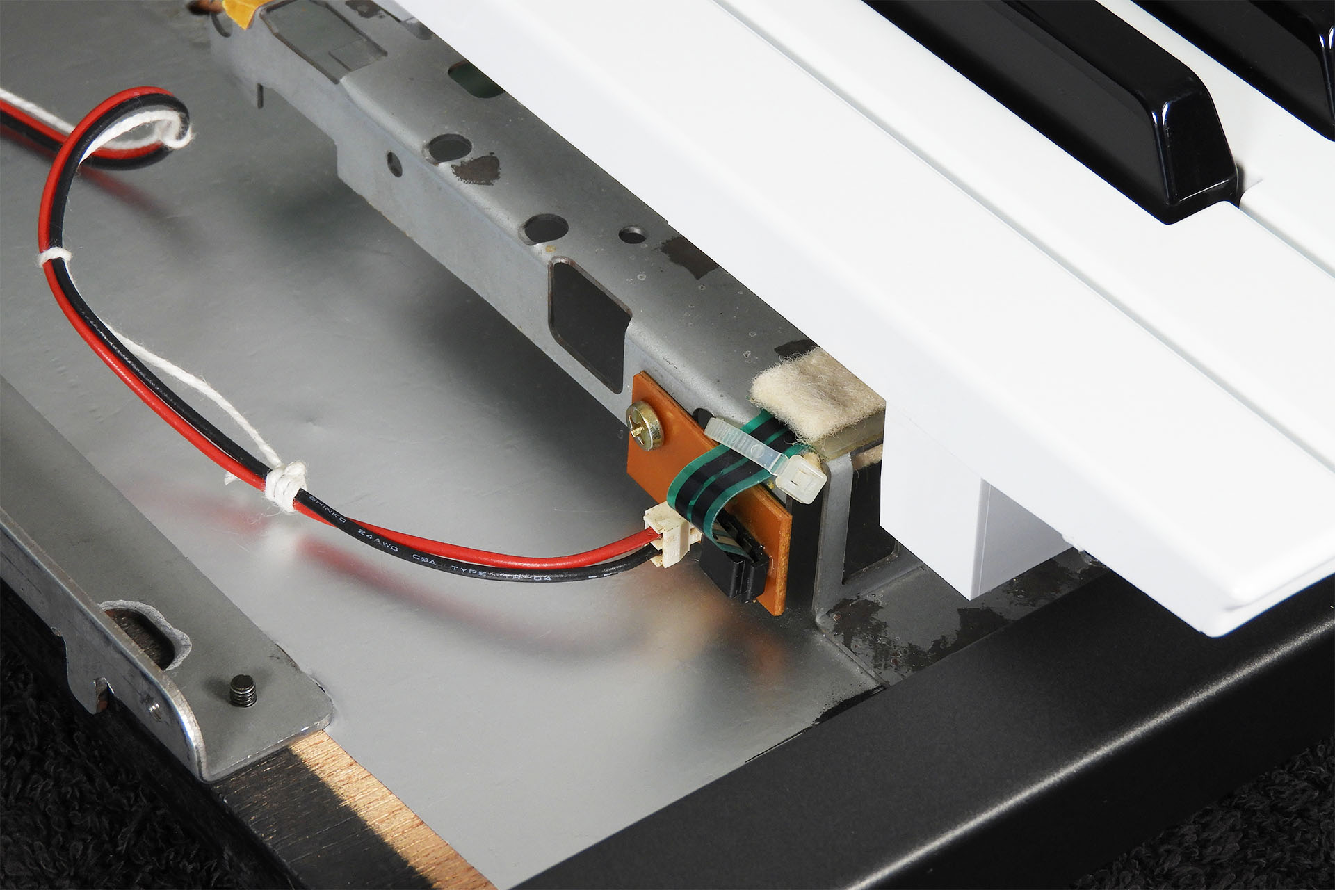
The JX-10's membrane type sensor terminates in a convenient plug-in 2-way connection situated to the left of the keyboard. Hey, no desoldering. 🙂 ... yet!
The original membrane-type aftertouch sensor terminates with a simple slide-in connection.
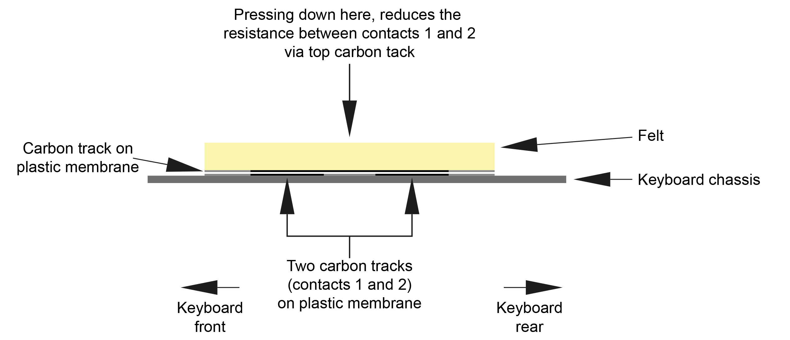
The anatomy of the original JX-10 aftertouch sensor is very simple and actually has a modern feel about it. With no metal parts, it only has three components (one of which is the top-felt) making it very low-profile and sleek.
Cross section of the original JX-10 original aftertouch sensor.
Well, I was pleasantly surprised; removing the old Roland aftertouch sensor was amazingly straight-forward and I hardly had anything to do when it came to cleaning the keyboard chassis.
Removing the old sensor was actually quite easy
Although the physics is different, the anatomy of the new sensor is quite similar to the original. Of course, being several decades since the release of the Roland JX-10, things have moved on and modern FSRs are much more reliable and with an actuation count of over 10,000,000, they're going to last a while.
My replacement aftertouch sensor for the Roland JX-10 is technically quite different but similar in its construction.
Once the keyboard chassis has been stripped and cleaned, dropping in the new sensor can be a little nerve-wrecking, even if like me, you've done a few. 🙁
A new AT-JX-10 replacement aftertouch sensor about to go in. It still makes me nervous!
To make life simple, my replacement aftertouch sensor for the Roland JX-10 includes a small FSR Aftertouch Interface PCB, otherwise known as FAI. Using Molex connectors, getting the signals off the FSRs is straight-forward. Originally wanting to develop a solderless kit, things didn't quite work out like that, though. Here's why...
My AT-JX-10 replacement aftertouch sensor for the Roland JX-10 will work fine if just connected to the volume-board (via FAI). The aftertouch control on the JX-10's front-panel however, will have a very short travel due to the higher output produced by the FSRs and the high gain of the aftertouch op-amp in the JX-10. Some will find the whole system too sensitive.
The gain of the the op-amp stage that buffers and amplifies the signal from the the aftertouch sensor, is a tad over 300. To calm things down, a resistor on the volume-board should really be changed if implementing this upgrade so while I was experimenting with the aftertouch gain stage, just like my AT-JX-8P project, I decided to incorporate switchable aftertouch sensitivity ranges into FAI.
My FSR Aftertouch Interface (FAI) PCB has a cool little secret on-board.
By simply moving a jumper on FAI, you can change the gain of the aftertouch op-amp stage. Even the high sensitivity setting however, is only about 50% of the original gain and it's ample!
Listening to the results as I experimented was bordering on hypnotic. You see, FSRs have considerably more dynamic range than the second-generation carbon-track transducers that Roland originally used in the JX-10. The conversion of human touch to sonic expression delivered by the new FSR-based system, is perhaps what Roland actually wanted to achieve back in the mid-eighties. Decades later, it's finally arrived and even although I say so myself, the feel is absolutely magical and in a different league to any JX-10 working aftertouch that I've tried.
I had to be sure however, that the MIDI response was also good. Hence, with the JX-10's aftertouch control on the front panel set to about 75% and an average finger pressure, I recorded the MIDI from a couple hits; one set with FAI in Norm mode and another with FAI in Hi mode.
With the aftertouch fader on the JX-10 at about 75%, I recorded a couple of hits into Cubase to test FAI's Norm and Hi modes.
As can be seen, the response of the FSR-based aftertouch sensor is nice 'n' smooth when FAI is set to Norm mode. Things happen quicker when FAI set to Hi mode. Full scale MIDI value 127 aftertouch can be reached in both modes. You just get there quicker and with less pressure, when FAI is in Hi mode. Note the nice linear response in both modes! 🙂
And don't forget; the aftertouch slider control on the JX-10's front panel works in both modes, as it did before.
My personal favourite configuration is have FAI set to normal and the aftertouch slider at about 2/3 full-scale. Here's a quick demo of a couple of classic factory sounds. The first is Poly Synth followed by Reverb Strings:
I recorded MIDI as well as audio, so you can see what's going on.
Guy lending me his JX-10 wasn't just about fixing the aftertouch in his instrument. It gave me the opportunity to measure up and design a rig so that my replacement aftertouch sensor for the Roland JX-10 could be 'manufactured' with precision and consistency.
While working on Guy's JX-10, visiting customers were asking questions about the open synth in my lab. Suddenly I had another JX-10 come in for one of my new replacement aftertouch sensors! Okaaaay...
I've now been able to test my AT-JX-10 on a couple of instruments and it works great! 🙂
If you want to buy my AT-JX-10 replacement aftertouch sensor for the Roland JX-10, you can do so here...
PACKAGING
The AT-JX-10 is sent out complete and in one straight piece. Although it weighs very little, the external double-sided carboard box is just under 1.2m long. Using normal courier methods worked out to be horrendously expensive and so I engaged the services of a shipping agent.
Packaging the AT-JX-10 starts with sandwiching it in between two pieces of hardboard. The wires are then neatly folded and secured to the hardboard with masking tape.
It's important that the sensor is kept straight so I sandwich it in between two pieces of hardboard.
To keep any moisture off the sensor during transport, the package is then put into a long polythene bag.
A polythene bag is then used to reduce the potential ingress of moisture and damp during its travels. FAI and any other bits are put into an electrostatic bag and then into a small bubble-wrap bag.
The protected sensor is then packed into a double-sided cardboard box and wrapped in black pallet-wrap which gives the package a little security and added protection against damp and moisture.
Final external packaging is pretty robust!
UPDATE: 21st May 2023
This afternoon who should pop over but my friend Guy Wilkinson to pick up his JX-10, now with fully working aftertouch. After playing with his JX-10 for a while, Guy said that he's now smiled nine times this week! 🙂
"I just picked up my JX-10 that I loaned to Alex of Plasma Music to develop an exciting new product. He has developed a new aftertouch sensor strip that simply reinvents the expressiveness of the keyboard. Simply put, I am so happy with this upgrade!!!
So we had a celebratory launch moment with my JX-10 in his fabulous workshop.
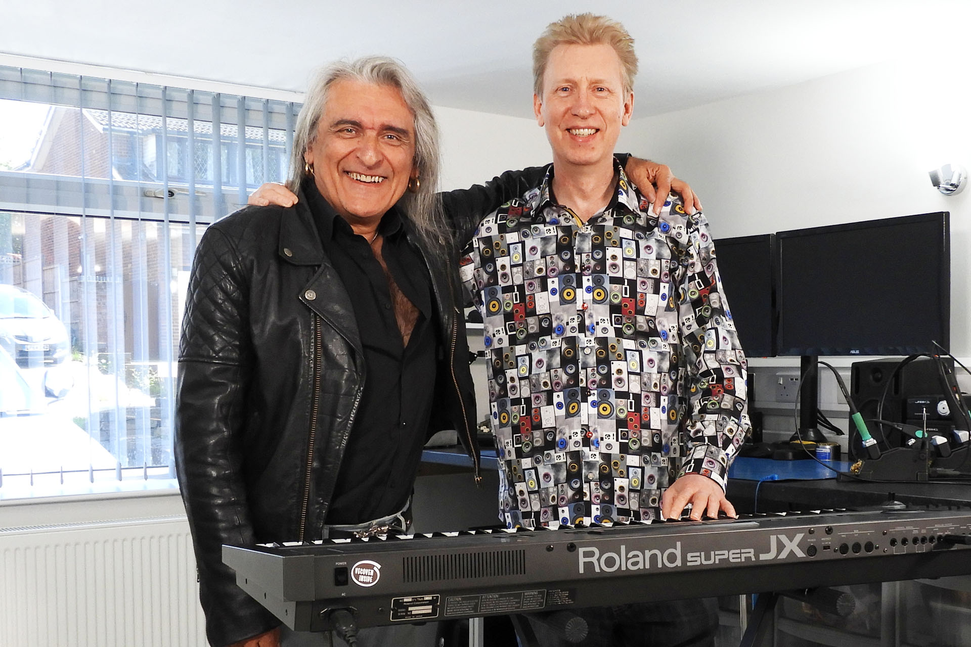
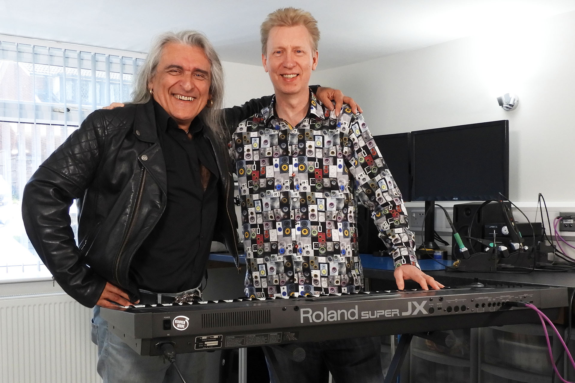
Alex, Guy and Roland JX-10... with new aftertouch sensor.
After checking out the technical aspects using the diagnostic menu, I started working through patches. Some non-factory patches need some adjustments in the patch menu, there are three settings for aftertouch: Vibrato, Brilliance, Volume – plus the sensitivity slider.
The factory patches have some really great settings for aftertouch and others just need a simple adjustment. Clearly the old strips didn’t work for very long because users who created and distributed patches didn’t configure Aftertouch parameters. As I worked through patches and editing settings, I breathed new life into them and I couldn’t help smiling as I played."
UPDATE - 29th May 2023
Now in development:
AT-AJ-2 - Aftertouch sensor for the Roland Alpha Juno 2.
AT-D-50 - Aftertouch sensor for the Roland D-50.
Please let me know if you're interested in these FSR-based replacement aftertouch sensors.
UPDATE - 29th June 2023
Just letting everyone know that my AT-AJ-2 replacement aftertouch sensor for the Roland Alpha Juno 2 is now up 'n' running. You can read all about it here.
UPDATE - 28th July 2023
My AT-D-50 FSR-based replacement aftertouch sensor for the D-50 is a go! You can read all about here.
Being able to convey feel to the sound after the keys are played, can transform a performance into something quite unique and almost magical. Indeed, Roland was definitely on to something when aftertouch began appearing on it’s synthesisers in the mid-eighties. Today, many classic synthesisers have aftertouch strips that either don’t work or are a shadow of what they used to be. Almost forty years later, my modern FSR-based replacement aftertouch sensor for the Roland JX-8P, has considerably more dynamic range and is infinitely more reliable than the first-generation transducers that Roland originally used in the JX-8P and transcends the instrument into another dimension.
I see a lot and I receive a lot of enquiries about failing or failed aftertouch (channel pressure) on the Roland JX-8P. Indeed I’ve been meaning to sort out a long-term solution for this rather well-known problem, for a couple of years. Well, I’m finally pleased to announce that my replacement aftertouch sensor for the Roland JX-8P is a go!
Aftertouch sensors in vintage keyboards have been a bit flaky even before vintage keyboards were, well… vintage! Launched in 1985, the Roland JX-8P soon became quite infamous for aftertouch issues. The problem was so bad that some unlucky customers were experiencing problems, having just bought their brand new instrument.
“So what’s the problem? ”
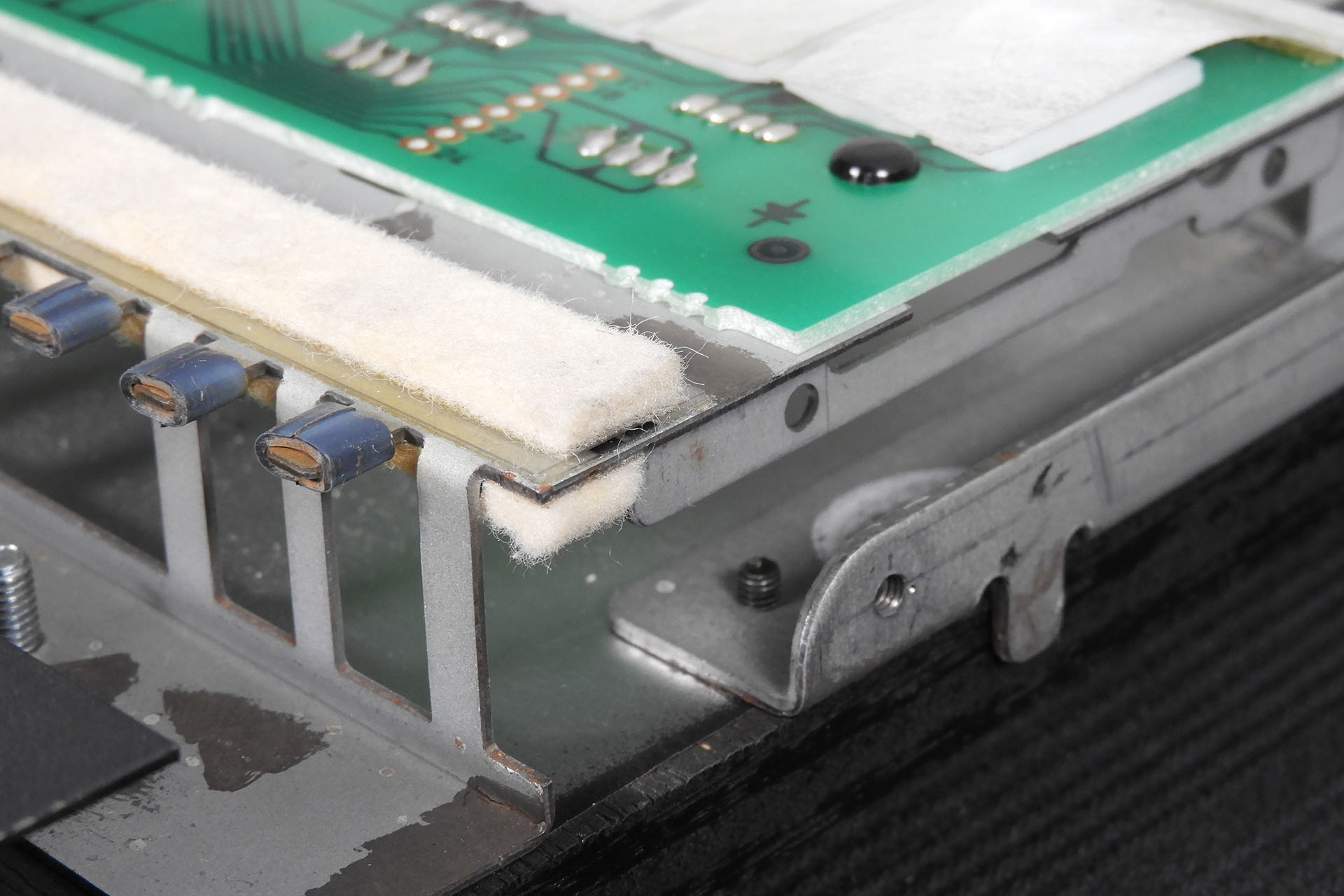
The aftertouch sensors in early instruments were extremely basic. In the case of the JX-8P, the sensor comprised of a very thin material which had two copper tracks on top of it. In fact a long thin PCB with two wide tracks would be a fair description! On top of the tracks are five conductive rubber strips, then another metal (steel) strip on top of the conductive rubber. Hang on, I’m not finished yet. The whole thing was housed in a kind of rubber extrusion, which in turn, had a strip of keyboard felt running its length. This elaborate assembly sits on top of the keyboard chassis, just under the front of the keys.
Cross section of the Roland JX-8P aftertouch sensor. Actually many instruments of the same era had very similar designs.
When pressing down on the aftertouch sensor, the top metal (steel) strip compresses the conductive rubber strips, thereby reducing the resistance between the bottom copper tracks. Not being hermetically sealed, the copper tracks are susceptible to oxidation and the ingress of contaminants. Over time, a layer of 'crap' develops on top of the bottom copper tracks and it doesn't matter how conductive the rubber strips are, increasing resistance between the tracks will inhibit any conduction of electricity. Don't forget that the stuff that's built up on top of the tracks, also stains the bottom of the conductive rubber strips, also reducing their ability to conduct properly. The sensitivity of the transducer deteriorates, sometimes quite quickly and the system eventually just dies. 🙁
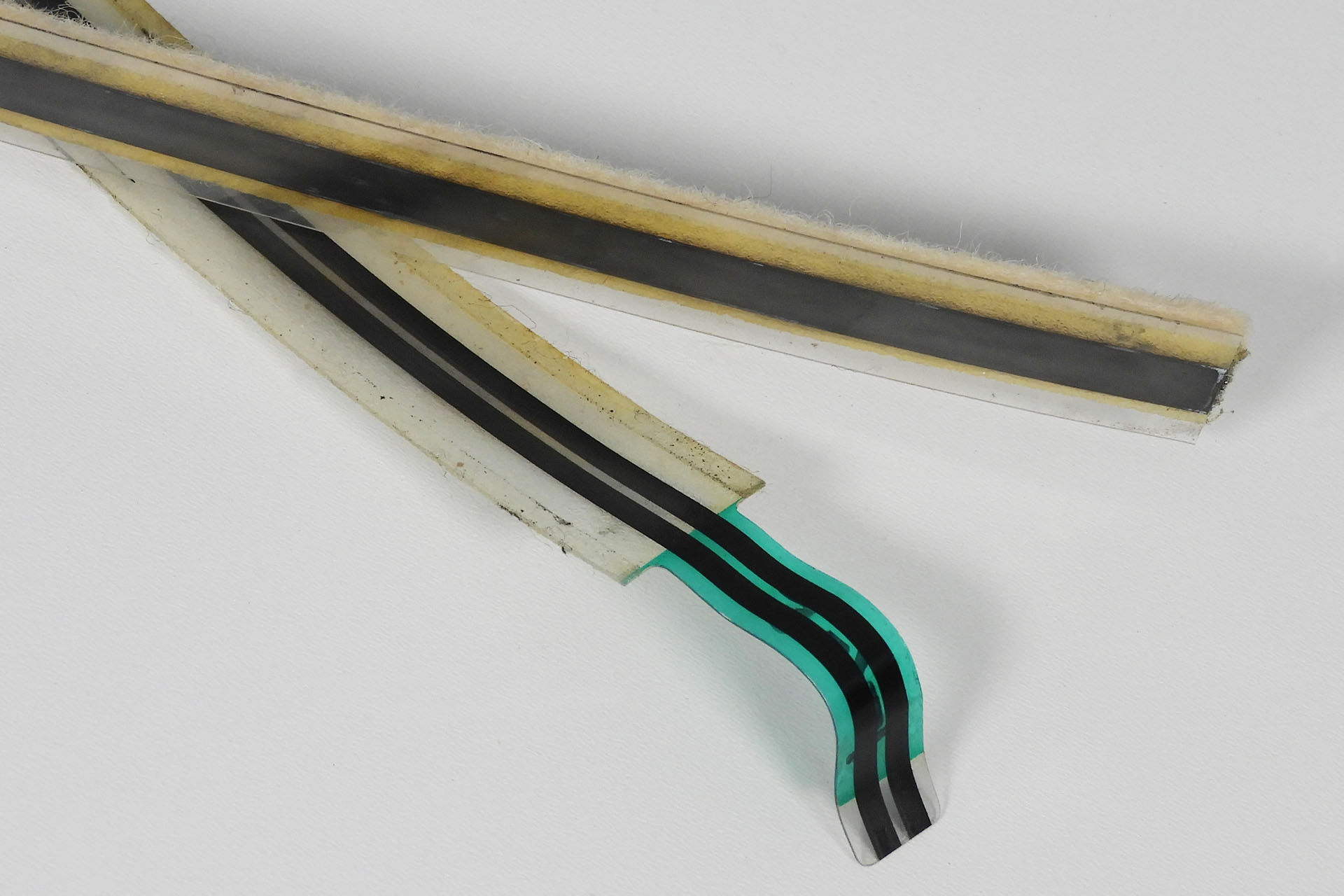
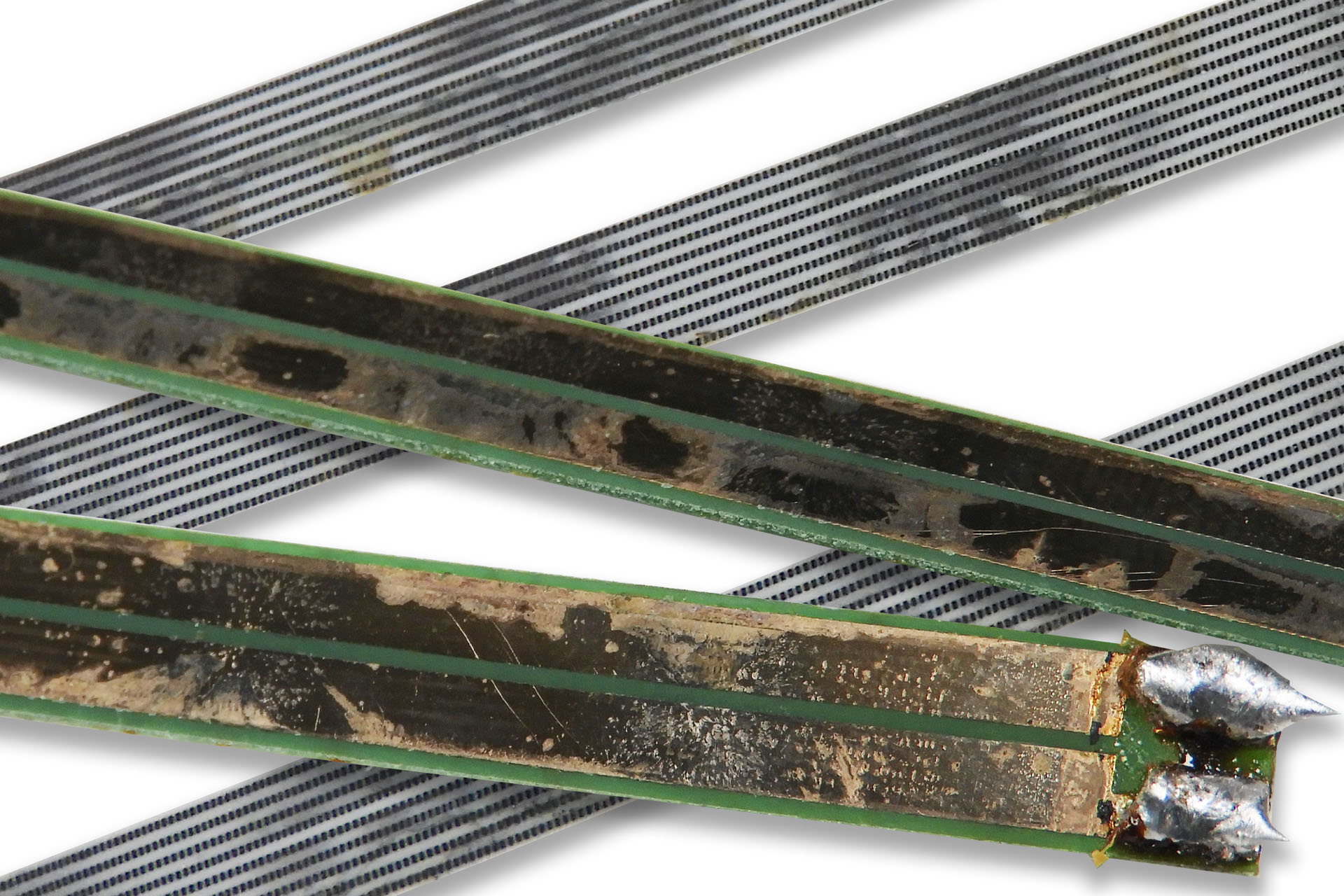
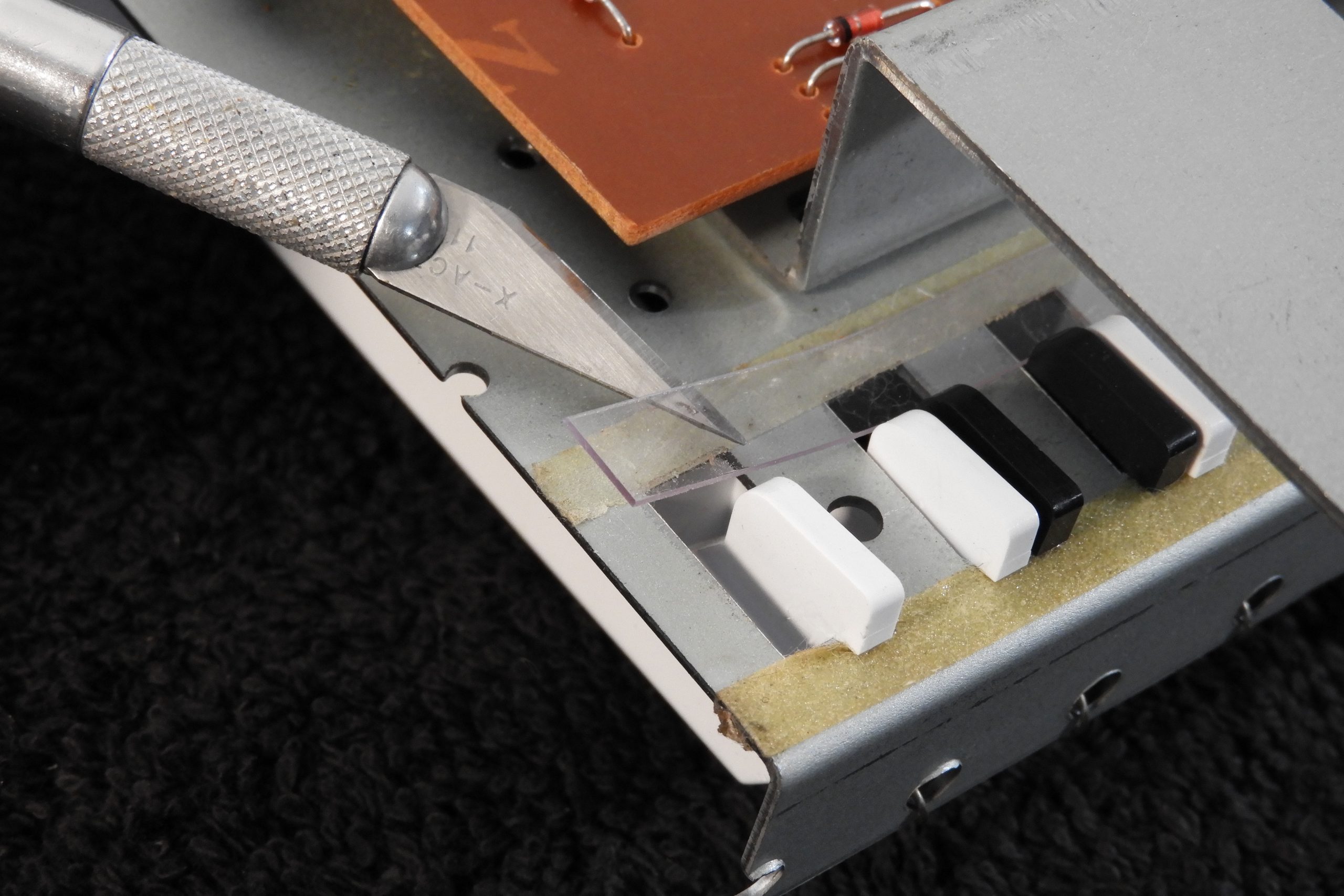
The image below shows sections of the bottom copper tracks of a JX-8P aftertouch assembly strip and three of the conductive rubber strips that sit on top of them. These were removed from an otherwise pristine, like, seriously museum-condition JX-8P.
The copper tracks should be bright, shiny and well... copper-coloured. The rubber strips should be clean and bright grey with black stripes. Neither should have marks, scratches or contaminants. Unfortunately, the Roland guys got this one badly wrong. A great idea but terrible implementation, delivering long-term unreliability.
Since the assembly was held together with glue (yes, you read correctly), when attempting to service an original aftertouch strip, disassembly has to be done carefully, glue needs to be (carefully) removed, the top metal strip must not be bent (which is actually quite easy to do) and cleaning the bottom copper tracks, oh and the conductive rubber strips, is all very time consuming and painful… and then you need to put it all back together again, reinstall the keyboard contact strip, the keys and the key retainer and then keep your fingers crossed that it kinda works. Oh boy.
SERIOUSLY?!?!?!? Well it was 1985. What else could they do?
Someone really needs to develop a
replacement aftertouch sensor for the Roland JX-8P!!!!!
When I was at Simmons, we developed two machines that used a new technology; force sensitive resistors (or FSRs). Coincidentally, these were invented in 1985, the same year that the JX-8P was launched. Being the only British electronics manufacturer at the time, to have an office in Tokyo, Simmons was often made aware of new technologies as soon as they broke and clearly saw potential for this new FSR thing.
The first FSR based instrument to be developed by the company was the Silicon Mallet, a 2-octave mallet played instrument with FM synthesis-based voicing.
The Simmons Silicon Mallet. Perhaps the first musical instrument to feature force sensitive resistors. I used to have one of these. Wish I kept it!
Then, in 1987 came the second instrument from Simmons to feature FSR triggering, the famous and truly impressive SDX which used ‘zone intelligent’ (or ZI) pads. Oh wow, I really enjoyed those days.
Photographed twenty years ago, here are my two Simmons SDXs from a previous studio (life). I still have them and hope I can get them back into my current studio soon.
Way too expensive at the time, Simmons simply wasn't able to incorporate FSR technology into it's other range of electronic drum and percussion products. I don't know, perhaps Dave had a long-term plan but well... not today. Although hugely powerful, at over 13,000 GBP (in 1987), the SDX wasn't exactly a big seller. External circumstances like the stock market crash in October '87, the cost of development of the SDX and challenging SDX sales, bust the company so there wasn't exactly much point in thinking to replace piezo sensors with FSRs, anyway! 🙁
And here's an old snap of my 'small' kit, comprising FSR, zone intelligent pads (except for the kick and small pad in between the centre cymbals). This soon expanded to double-kicks, a few SDX ZI cymbals, another snare and a lot more toms. Hence the reference, 'small kit'.
Fortunately, FSRs have come a long way since the late eighties. Today, FSR sensors are nicely sealed units and don’t have to be ‘assembled’ by the end user in hermetically sealed environments. Yeah, that bit was a real pain. The smallest bit of dust could render a pad useless.
FSRs have been used as aftertouch sensors in instruments for a while now. As perhaps Dave Simmons had originally intended, FSRs have also replaced the old piezo triggers in some manufacturers' electronic drum pads. Being very aware of this and what with my experience from my days with Simmons, for the past couple of years, I’ve been meaning to test some FSRs to see if they can be used to make a replacement aftertouch sensor for the Roland JX-8P and possibly other older instruments.
Cross-section of a force sensitive resistor (FSR) illustrating how they work.
Being basically refined versions of the type of carbon-track sensors that Roland originally used but delivering a lot more dynamic range as well as other benefits, FSRs are perfect for this kind of application. In fact, modern aftertouch sensors and even some drum pads use FSRs. The principle is the same but the resistive polymer material is of a modern composition and the manufacturing process makes FSRs considerably more robust and reliable than previous pressure sensors.
Of course you can’t just use any FSR. The first obvious challenge is finding something that's close if not exactly the same dimensions as your original aftertouch strip. Unlike those old sensor assemblies, modern FSRs are very thin. Also, being incredibly more sensitive, oversensitivity may have to be considered and it may even be necessary to add buffering, attenuation or amplification circuitry. Try to keep it simple, right?
Well, stuff all that! For test purposes, I was able to use off-the-shelf devices which worked just great. I was so pleased. The next challenge was how to attach readily available sensors to the JX-8P keyboard chassis and retain the feel (or better it) of the original keyboard.
After messing about with a whole bunch of FSRs to get my replacement aftertouch sensor for the Roland JX-8P working properly, I ended up covering the FSRs with a layer of rubber and then a layer of felt. The felt reduces mechanical noise produced when the keys finish their travel. If it wasn't there, hitting the keys would be err... noisy! When fitting the sensor assembly, proper alignment is crucial, so as to ensure a uniform aftertouch response across all keys. After putting things back together, I was delighted that my simple assembly delivered a lovely physical feel to the keys, something I was quite concerned about. The whole exercise would have been a waste of time if the keyboard didn't feel right.
Compared to the old Roland sensor strip, my replacement aftertouch sensor for the Roland JX-8P comprises only three components instead of five, there are no exposed copper strips that'll oxidise and FSRs make the the system considerably more reliable. Theoretically, this should be an install and forget replacement.
Cross section of my replacement aftertouch sensor for the Roland JX-8P is a much simpler affair than Roland's original device.
You may notice that in the diagram above, the FSR doesn't run the full width of the rubber that sits on top of it. Actually, it's the other way around; the rubber is wider than the FSR (as is the piano felt). That very, very small gap is taken up with double-sided adhesive tape. The FSR also has adhesive tape underneath it and since the FSR is only 0.41mm thick, there's not actually going to be any substantial gap in real life! 🙂 The felt (in red) is definitely narrower than the rubber but considerably wider than that on Roland's original sensor. Some very sensitive fingers may notice an increased smoothness and a nicer feeling cushioning effect when playing the keys.
The dynamic range of the FSR-based sensor is considerably more than that of Roland's first generation aftertouch transducer. Hence, on the first two prototypes, I deliberately positioned my new sensor so that the effective FSR area sat slightly more forward (towards the front of the keys) than the original device. The increased sensitivity of the new sensor was thereby compensated by the slight increase in pressure required to generate an aftertouch signal.
Hey, if you prefer increased sensitivity, then carry on reading 'cos this design has a little trick up its sleeve.
So I've made reference to FSRs (plural) and not FSR (singular). I think I've hinted that finding a single transducer that would run the length of a 61-note (let alone a 76-note or even 88-note) keyboard is virtually impossible. I did however, find a transducer that would run more than half the length and so I tried using two. Guess what, that idea worked too.
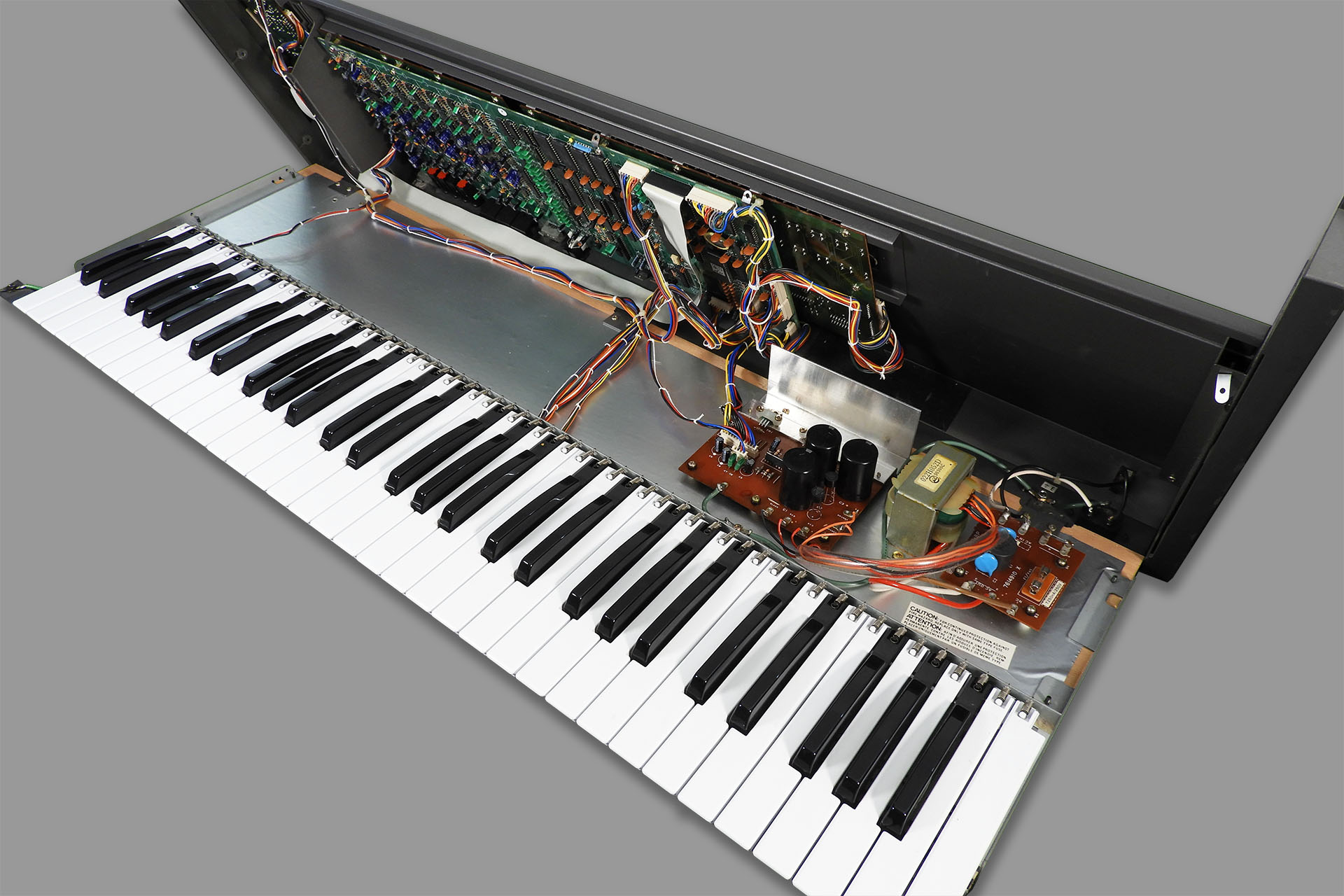
Opening the JX-8P requires the removal of three screws on each end cheek and two screws from underneath the instrument, towards the pitch-bend assembly. In the rather familiar but still elegant manner and indeed similar to many eighties keyboards, the top chassis folds up and back as it's hinged at the rear of the instrument, to the wooden base.
Eight screws and a gentle lift up and back and voila, a lovely example of a Roland JX-8P, is now open. If only everything in life was so simple (and gorgeous).
It's unfortunate that the keyboard chassis has to be removed and fully disassembled but considering what the aftertouch sensor does and where it is, it kinda makes sense. More importantly, further on down in this post, I write about removing the glue that was used to attach the Roland aftertouch strip to the keyboard chassis. That's a real task and I wouldn't want to do that with the keyboard chassis inside the JX-8P, to be honest.
There's a plastic strip running the length of the keyboard, that's underneath and at the back of the keyboard chassis that helps secure the keys. If it wasn't there, the keys would only be held in place by a small spring and could easily be pulled forward.
Common to virtually all Roland keyboard assemblies, is the key retainer strip which is underneath and at the rear of the keys. This plastic strip needs to be peeled off, to remove the keys.And as you can see, the plastic key retainer (part of which is highlighted in red) kinda runs underneath the cable-tie binding posts, making simple removal of this component impossible without removing the contact PCBs. Grr....
To remove the whole strip, you have to remove four cable-tie binding points. To remove the cable-tie binding points, you have to remove the contact boards (yes, there are two in the JX-8P). What could have been a quick job, is now going to take a little longer.
Yes, there is a cheat for this but I wanted to work on the bare metal chassis without concern about anything else.
Three wires come off the pitch-bend assembly and go in the direction of the aftertouch strip. The black wire is simply connected to the keyboard chassis. The red and grey wires go to the aftertouch strip. Since the aftertouch strip is basically a resistor, it's not polarised, i.e. it doesn't matter which way around these wires go.
It’s easy enough to desolder the two connections between the original aftertouch strip and the pitch-bend assembly PCB but I would recommend just cutting them. The type of wire Roland used doesn't even need tinning.
My replacement aftertouch strip is secured with double-sided adhesive tape and so after removing the original strip, the top of the chassis MUST be fully and properly cleaned, prior to attaching the replacement sensor. This is a long and tedious job so I had a lot of coffee and biscuits on the side.
The bare keyboard chassis with only the original aftertouch sensor to remove.
Since I was working on the bare metal chassis, I wasn't worried about experimenting with various chemicals and methods to remove the residual double-sided tape, glue and other gunk. I found that DW-40, helped loosen it up a bit. Next it was long and strong finger-nail time, as I scraped off the leftover glue. A dirty and slightly painful job, I'm afraid. Once satisfied that the bulk of the glue had been removed, I used IPA, heavy-duty tissue and an old toothbrush, to get rid of all hints of glue and WD-40. It wasn't just a case of wanting things to look nice. It's really important to do this as the new aftertouch assembly simply won't adhere to the chassis if it's greasy.
Removing all traces of the original, almost forty-year-old aftertouch sensor is a long and messy job but it has to be done.
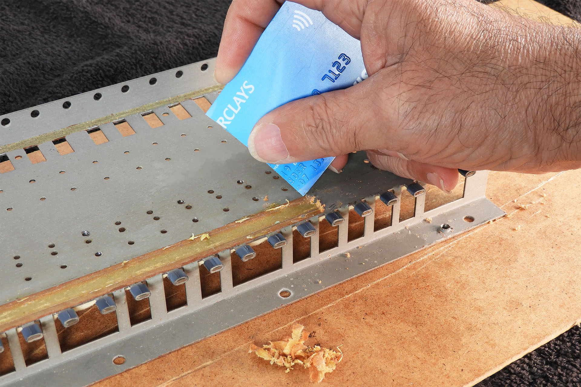
Although I didn't find a shortcut to getting rid of the old Roland glue, when I installed my second replacement JX-8P aftertouch sensor, I decided to use the cut edge of an old credit card. Yeah, I know but they do come in really handy. Clearing a millimetre of glue at a time, the process was just as tedious so you're still going to need the coffee and biscuits but... it was a lot less messy and one could argue that with less clearing up to do afterwards, it was a little quicker.
Don't throw away those expired credit cards! They can come in useful, sometimes.
The theory of replacing the original pressure sensor with a FSR-based system worked first time on my prototype. There were however, some interesting physical challenges and well, life's just boring without challenges, right? 🙂
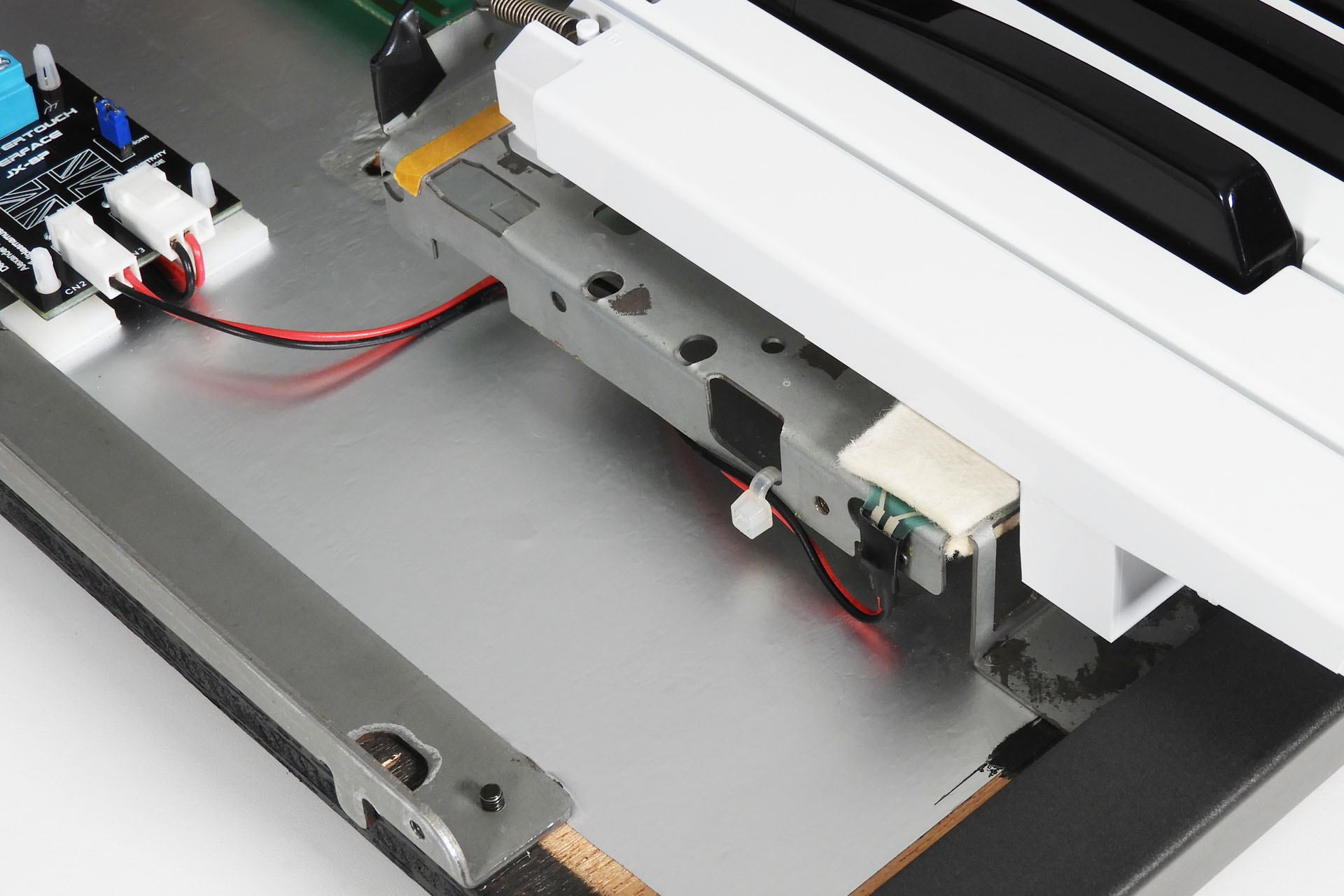
The original Roland sensor is a single device with terminals on the left-hand side. I used two FSRs and the right-hand FSR terminals would somehow have to be folded and connected. Of course, there’s very little room between the right side of the keyboard chassis and the inside of the right cheek, for example. “Not a problem” I thought. “With so much space underneath the keyboard chassis, I’ll just run my connecting wires there”… I thought.
Well, for starters, right underneath the front of the keys and underneath the keyboard chassis is a small felt strip which does the same job as the felt strip on top of the aftertouch sensor; it dampens any mechanical key-noise but when the keys are released and not when they’re depressed. I definitely didn’t want to obstruct that. You can just make out the felt strip at the bottom-centre, in the two pictures above.
The two wires from the right-hand FSR could have run in the small gap between the key-contact assemblies and the bottom of the keyboard chassis. In fact, I tried that and initially this seemed like a groovy route to get the wires from one side of the keyboard to the other. You have to think long-term though, and I was concerned that in time, this arrangement might cause snagging issues as it wasn't easy to properly secure the wires. Hence, I ruled out that approach too.
In the end, my solution was to simply bend the wires coming off the FSR, directing them towards the rear of the keyboard chassis and get them to eventually join Roland's lovely wiring loom that's well out of the way of anything. If you remember, the wiring loom is secured with cable-ties that are attached to small plastic anchors along the rear but underneath the chassis and which cover the plastic key retainer strip. This required me to follow a specific sequence when reassembling the whole keyboard and replacing the keys but it was still the most ideal way to go. Oh PEEEEERFECT!!! 😊
There's very little space to do anything fancy on the right-hand-side of the keyboard so the wires coming off the second FSR are bent sideways towards the rear of the keyboard chassis and not backwards so as to go underneath it.The keyboard turned upside-down, things may be a little clearer.
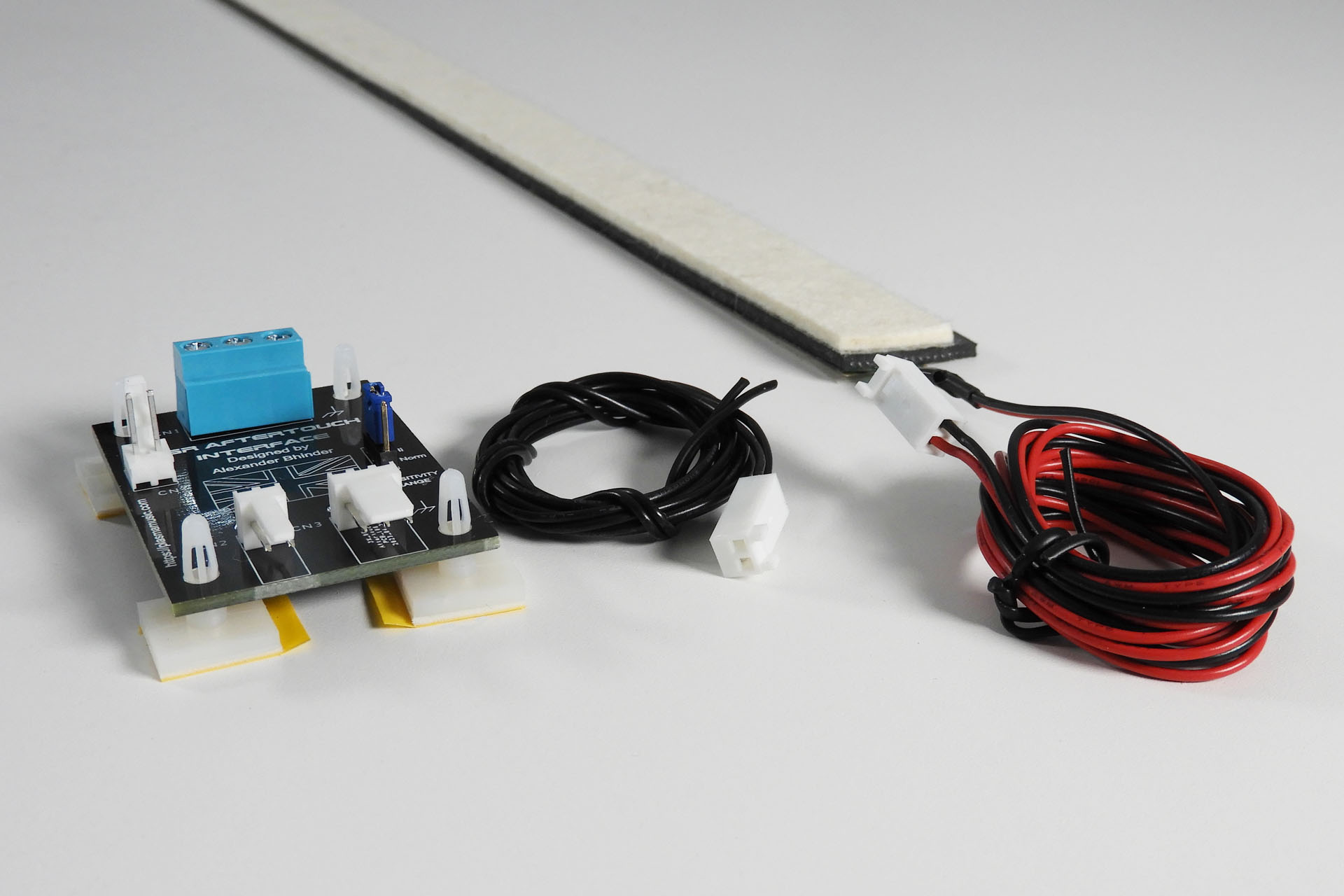
Apart from developing a more reliable and seemingly permanent fix to the JX-8P aftertouch problem, I wanted something that could be installed by almost anyone with a little technical competence and therefore aimed at developing a solderless solution.
I’ve tried to keep things simple (haven't I said that before) and so to that end, the connection of the replacement aftertouch sensor to the wires that go to the pitch-bend assembly, is done via a simple (passive) PCB that I knocked up. The wires from the FSRs are terminated with female Molex connectors that snap into male connectors on the PCB. Thinking ahead, I put a 3-way connector on the wires coming from the left-hand FSR. This allows for easy (and tidy) connection of the original earth wire that ran from the pitch-bend assembly to the keyboard chassis. The wires from the volume-board are attached to the PCB via a terminal block. All you need is a small screwdriver.
My FSR Aftertouch Interface PCB is secured to the JX-8P's wooden base, with supplied self-adhesive standoffs which I found to be more than adequate. I guess you could use small nylon spacers and then screw the PCB to the base, if you wish. If you're JX-8p is NOT going on a deep-space mission however, I would stick to plan A!
NCC- JX8P enroute to a galaxy far, far away in search of new life, new civilisations and err... 1985, perhaps.
Now then... so I've said that I wanted to keep things simple and that one of the objectives of the project was that my replacement aftertouch sensor for the Roland JX-8P should be a solderless upgrade. Well, it is but there's a but...
Things will work okay when connecting the system to the JX-8P's aftertouch circuitry but (told ya'), some may find the response and feel a little too sensitive. That's because the output from the new FSRs is considerably higher than that generated by the old sensor. So if you do have knowledge and experience of working on electronics, you might want to consider unlocking the FSR Aftertouch Interface PCB's cool little secret... which is even more cool when you think it's just a passive build comprising a couple of connectors and resistors!
My FSR Aftertouch Interface, otherwise known as FAI; a clever little PCB that hides a rather cool secret.
Impossible to compare the response of the new FSR-based sensor with that of the original sensor as it was in 1985, I could only really use a modern MIDI controller keyboard connected to a JX-8P as some kind of reference. Having friends over allowed me to experiment with different 'hands' (if you know what I mean) and the experience gave me valuable data pertaining to the gain of the aftertouch buffer / amp stage of the JX-8P and how to potentially adjust this for the new type of sensor.
Having an opportunity, I ended up designing my FSR Aftertouch Interface PCB with the facility to provide switchable aftertouch sensitivity ranges. Removing one resistor on the JX-8P's volume-board and substituting two wires (supplied with the kit) in its place, by simply moving a jumper on FAI, you'll be able to switch between two sensitivity ranges. The 'Norm' setting is nice and smooth and I'm guessing close to what the original aftertouch might have felt like. The 'Hi' setting on the other hand, is a little more spontaneous, requiring less force to produce an aftertouch signal.
How fringin' cool is that?!?!? 🙂
Testing the two settings with the aftertouch slider on the front panel of the JX-8P at about 80% and a nominal finger pressure (nothing heavy), I recorded a couple of hits into Cubase.
With the aftertouch fader on the JX-8P at about 80%, I recorded a couple of hits into Cubase to test FAI's Norm and Hi modes.
As you can see, in Hi mode, the attack curve of the aftertouch response is steeper and a full 127 aftertouch reading happens quicker. Of course, the aftertouch slider on the top panel of the JX-8P, can still be used to trim the feel of the aftertouch in either mode.
The only downside is that you'll need to desolder a resistor and to do that, you'll need to remove the volume-board to do that but like I said, only for experienced tech dudes!
Once everything was working, I just couldn't stop playing. Wow, this is something else! Testing gear shouldn't be this much fun! 😀 The JX-8P was like a new instrument. What a transformation.
This has been a fun little project. My replacement aftertouch sensor for the Roland JX-8P is now installed and working in a couple of customers' instruments. The second challenge however, was converting the project into a package which could be sent out to JX-8P owners / users and installed with minimal hassle. Well, I managed to do that too and and I've also just finished compiling the accompanying detailed and fully illustrated installation instructions, which means that you can now order my AT-JX-8P kit here.
MIDI analyser showing channel pressure... at last!
Allowing me to experiment on their machines, two of my customers (Clive and James) are stunned (in a good way) with their Roland JX-8Ps, both having been brought back to life, with fully working aftertouch. In fact, I soon developed a similar transducer assembly for the 76-note Roland JX-10. Unlike the JX-8P, the JX-10's aftertouch strip used a pair of carbon tracks instead of the two copper tracks. There's also a noticeable absence of the steel top strip, conductive rubber strips and the rubber housing. Anyway, enough Super-JX nonsense. As soon as I've got a little time, I'll post full details of my replacement aftertouch sensor for the Roland JX-10.
My dear friend Guy Wilkinson (you all know Guy, right) leant me his JX-10 as a test bed. Thanks, Guy! 🙂 It was a perfect subject because guess what... the aftertouch was shot. The construction of the JX-10 is a little more evolved than that of the JX-8P but functionally, it's very similar. Under the bonnet, it's quite apparent how Roland implemented what it had learnt from previous synthesisers like the JX-8P but still retained all the good stuff.
If you want to buy my AT-JX-8P replacement aftertouch sensor for the Roland JX-8P, you can do so here...
As with everything I make, I've tried hard to keep costs down. Not being a massive corporation, I'm limited by things like the quantities of components that I can buy at any one time. For something like this replacement aftertouch sensor for the Roland JX-8P, I had to make a special assembly jig so that I could keep things straight, precise and consistent. It's not just a case of knocking stuff up and shipping. Each assembly is tested and even just to collect the reference data was a task in itself.
I'm therefore hoping that the price is favourable to most and that the majority of JX-8P owners / users will appreciate the efforts that go into designing and building these kind of upgrades.
I design and make stuff because I enjoy the challenges and I want to help keep as much vintage gear going as long as possible.
PACKAGING
The AT-JX-8P is sent out complete and in one straight piece. Although it weighs very little, the external double-sided carboard box is just under 1.2m long. Using normal courier methods worked out to be horrendously expensive and so I engaged the services of a shipping agent.
Packaging the AT-JX-8P starts with sandwiching it in between two pieces of hardboard. The wires are then neatly folded and secured to the hardboard with masking tape.
It's important that the sensor is kept straight so I sandwich it in between two pieces of hardboard.
To keep any moisture off the sensor during transport, the package is then put into a long polythene bag.
A polythene bag is then used to reduce the potential ingress of moisture and damp during its travels. FAI and any other bits are put into an electrostatic bag and then into a small bubble-wrap bag.
The protected sensor is then packed into a double-sided cardboard box and wrapped in black pallet-wrap which gives the package a little security and added protection against damp and moisture.
Final external packaging is pretty robust!
The Roland JX-8P - A Lot of History
The forerunner to the Super-JX, the Roland JX-8P was one of the most successful synthesisers ever. What do I mean by ‘successful’?
Well, for a start, Roland simply couldn’t make enough of them and despite having gone through several revisions under the bonnet, the JX-8P ended up being produced in huge quantities and selling by the truckload, all over the world.
Secondly, the feature packed JX-8P has appeared on countless hit records. Artists absolutely loved using this machine for their live performances, too. The JX-8P sounded like a million dollars and looked ultra-cool. In fact, some artists used several, in their live sets.
With designers like Fred Vecoven and Guy Wilkinson producing peripherals to keep our favourite vintage instruments going, my replacement aftertouch sensor for the Roland JX-8P is but a humble contribution to the community.
Don't hesitate to contact me, if you have any questions. In the meantime, here are some Roland JX-8P resources:
Oh! I didn't realise how popular this would be! Thank you to all who pre-ordered. I'm expecting to have everything I need to start supplying these, in about a week (the first week of May).
UPDATE- 3rd May 2023
First week of May and as promised, everything's in stock for me to offer this great little kit. 🙂
UPDATE- 10th May 2023
The aftertouch factory! Word gets around quickly.
A week after my last update and another two JX-8Ps and another JX-10!
UPDATE - 21st May 2023
This afternoon who should pop over but my friend Guy Wilkinson to pick up his JX-10, now with fully working aftertouch. After playing with his JX-10 for a while, Guy said that he's now smiled nine times this week! 🙂
"I just picked up my JX-10 that I loaned to Alex of Plasma Music to develop an exciting new product. He has developed a new aftertouch sensor strip that simply reinvents the expressiveness of the keyboard. Simply put, I am so happy with this upgrade!!!
So we had a celebratory launch moment with my JX-10 in his fabulous workshop.
Guy Wilkinson collecting his lovely Roland JX-10.
After checking out the technical aspects using the diagnostic menu, I started working through patches. Some non-factory patches need some adjustments in the patch menu, there are three settings for aftertouch: Vibrato, Brilliance, Volume – plus the sensitivity slider.
The factory patches have some really great settings for aftertouch and others just need a simple adjustment. Clearly the old strips didn’t work for very long because users who created and distributed patches didn’t configure Aftertouch parameters. As I worked through patches and editing settings, I breathed new life into them and I couldn’t help smiling as I played."
UPDATE - 29th May 2023
Now in development:
AT-AJ-2 - Aftertouch sensor for the Roland Alpha Juno 2.
AT-D-50 - Aftertouch sensor for the Roland D-50.
Please let me know if you're interested in these FSR-based replacement aftertouch sensors.
UPDATE - 29th June 2023
Just letting everyone know that my AT-AJ-2 replacement aftertouch sensor for the Roland Alpha Juno 2 is now up 'n' running. You can read all about it here.
UPDATE - 12th July 2023
When you get e-mails like this, it makes it all worthwhile:
Hi Alex,
I have installed it now.
Its amazing! What a great job you did inventing this!
The feel is so great. I will definitely buy this for my own JX8P as soon as I get the funds.
Installation was easy, great manual. I have found it practical to use one of the large hardboard pieces from the packaging to align the at strip to the chassis. I clamped it onto the chassis left and right and aligned it so that I got the 2mm clearance as recommended.
Over recent months, customers popping over to drop off or pick up gear, have all commented on the collection of vintage hi-fi speakers in my lab. Well, today they'll be delighted to hear that after several months, Plasma Music launches Upcycled Audio! So, what's it all about?
Donors for my first Upcycled Audio project.
Okay, so my first Upcycled Audio project involves converting some vintage but lovely passive hi-fi speakers to Bluetooth!
One of each of a matching pair of these speakers either has been or is being fitted with a Bluetooth 5.0, 2 x 30W amplifier module.
Bluetooth amp module fitted with matt-black anodised aluminium ('posh') knobs. Perhaps a little impractical in the dark but... they look cool.
Most of the speakers are Mission M72s. That's because I know them very well. If you know your hi-fi, you'll notice a pair of smaller Mission M71s next to the M72s on the left. There are also a pair of Tannoy 631s and a pair of Jamo Cornet 30s (far right). I'm only interested in speakers that had a reputation and that are in reasonably good condition.
The Bluetooth amp module is built into only one of the speakers.
The crossover in the speaker that houses the module has been modified so for stereo operation, all you need to do is link the speaker terminals between the speaker with the module, to the speaker without the module. 2m of high-quality speaker cable terminating with 4mm plugs on each end is included with the speakers.
Simply link the speakers via the speaker terminals for full stereo.
The crossover mod' doesn't affect the sound. All I've done is cut some tracks and add a couple of links, so that one channel of the module can be wired internally, while the other channel is directed to the cabinet's speaker connections and hence, the other speaker.
The module is powered by an included 12V power supply with standard 5.5mm x 2.1mm DC plug. A small blue LED that deliberately isn't bright and obtrusive, confirms power status. I hate big shiny lights on gear!
You'll also notice a 3.5mm jack socket (AUX IN) on the module panel so YES, you can plug in an analogue stereo feed.
The module can be powered by any DC voltage between 9V and 24V but I found that 12V at 3A, provides the best results.
Despite this being a new project, prototypes have been extensively tested and I'm delighted to report that these things sound AMAZING!!!! 🙂 I'm not just saying that. I'm shocked at the quality of the Bluetooth 5.0 module and the D-class amp. The sound is solid, defined, crisp and well, just sweet. Forget your cheepo, Buy On-Line, made in the far east, crap. This is proper hi-fi!
So you know I said that I'm rather familiar with the Mission M72s. Well, that's because I've been using a pair in my control room for many, many years. They're great to check mixes on hi-fi speakers. In fact, you might have already noticed one in the background image of this website!
I've been using Mission M72s professionally for decades.
My Upcycled Audio speakers are supplied with a standard set of glossy black aluminium knobs, a 12V / 3A power supply and 2m of high quality speaker cable that's terminated at both ends, with 4mm connectors. All you need to be up 'n' running is a music source. 🙂
Customers will have the option to buy longer speaker cables, DC cable extensions and what I call 'POSH' knobs.
Standard knobs are shown in the image below. The posh knobs (featured in the pictures above) are brushed, matt-black anodised aluminium and have a slot as the position marker as opposed to a white line. To be honest, while they look mega-cool, they're not too easy to visually adjust in the dark (go figure)!
Here's the back of a Mission M71 with Bluetooth 5.0 2 x 50W module and gloss black (standard) aluminium knobs. These guys have a white line position indicator.
If these speakers are destined to sit on a shelf or a similar flat surface, then you may be interested in a set of optional, self-adhesive rubber feet.
If you're going to be putting them on speaker stands, then you shouldn't need the feet.
Although straight-forward, I still feel obliged to compile a user guide so that's going to take a little while.
With standard accessories, a pair of these speakers will cost no more than 400 GBP excluding delivery. Being quite substantial, shipping is going to be a lot so at the moment, these will be 'collection only' and I'm not looking to export these.
Labour intensive, these Bluetooth hi-fi speakers will be slowly trickling into my e-store over the next few weeks so for the time-being, please just contact me if you're interested. 🙂
Here are a pair of Black Mission M72 that have also been converted. In fact these were my prototypes.
So if you've read my rtpMIDI Adventures post from 9th May 2022, you'll note that I had problems accessing the PC ports on my Nord Micro Modular. Well, here's how I eventually got to access a Nord Micro Modular in 2023.
Well firstly, for those that aren’t familiar with the Nord Micro Modular, let me take a short step back. Launched in about 1997, the Nord Micro Modular hosted a revolutionary concept for the time. Having two pairs of MIDI ports, one pair was used exclusively to program the machine via some beautifully graphic software (for the time), running on a computer. If you're curious, you can read more about this range, here.
Notice the two pairs of MIDI ports on the Nord Micro Modular. One pair is used to program the unit.
Anyway, in my previous post, I mentioned that the Micro Modular’s PC ports could be flaky, even back in the day and with my new rtpMIDI set-up, things weren’t any better. The irony here is that it was a well-known fact at the time, that an unreliable connection to the Nord’s PC ports was inevitably due to a ‘slow’ MIDI interface. Remember that USB only came out in 1996.
I tried bypassing my new rtpMIDI network and attached the Nord directly to my Windows 11 computer. Ruling out rtpMIDI and the iConnectivity mio XLs, I tried several MIDI interfaces and it now seemed that the problem was either computer hardware or operating system related.
In the end, I took the Nord down to the lab and pulled out an old Apple G4 Cube I had all wrapped up in the loft, to experiment with older hardware and OS. Although there was an editor for Mac OS 8 / 9, it seemed like Nord was really addressing the Windows users market, so it might have made more sense to mess around with an old XP or perhaps even a Windows 7 machine. Unfortunately, I didn’t have anything like that conveniently to hand. Hence, my decision to have a go with my old Apple Cube.
I normally deal with vintage synthesisers and guitar amps. My computers are all fairly up-to-date so working with this original Apple Cube was a bit weird.
To cut a long story short, my Apple Cube running OS X Tiger (10.4.1.1) in conjunction with an old M-Audio MIDISport 2x2 worked just great.
NOTE: Nord only had a beta version of the Modular editor software for OS X but I also found this great website which is trying hard to keep the editor alive for this platform; http://www.stage-engine.com/micro-modular-1.
So, if you're a little persistent like me, there's one more thing to try...
I connected my Cube to my network and you guessed it, I made a session in rtpMIDI for the Nord's PC ports, tried to connect and guess what... it didn't work! 🙁
So it seems that there's a combination of just too many things that prevents the Nord editor communicating with the hardware, in a modern set-up. Such a shame.
Anyway, with no fan, one would expect the Cube to be nice and quiet but by today's standards, the electromagnetic hard drive makes this cute little thing way too loud to have in a recording environment. I built my studio computers myself and they're seriously quiet but I still keep them in a cupboard in a separate room to the control room. Even tucked away in that cupboard, I wasn't convinced that I wouldn't hear the Cube.
So I had this whacky idea to replace the HDD with a small SSD type but the drive interface in the Cube is PATA IDE and everything’s packed really tightly in that little precursor to the Mac Mini. I did find some resources on-line as the HDD / SSD transplant idea, obviously wasn’t unique.
Being IDE based, replacing the electromechanical HDD with a (no moving parts) SSD wouldn’t make the machine much faster but it would make it dead quiet and so to that end, I cloned the Cube’s drive to an old 60GB SSD I had lying around. It all worked so if anything, at least I’ve ended up with a silent Apple Cube, now! 😊
My very first SSD, a 60GB ADATA that’s got to be well over twelve years old, has a new home in my Apple G4 Cube.
I set up Apple Remote Desktop on the Cube to accept VNC connections and although a little draggy, running VNC on either my studio PC or Mac worked fine.
SIDE NOTE - For anyone insane enough to try remote access to a computer this old, please note that changing the computer's desktop background to a solid colour (unlike that shown above), really speeds things up.
No desktop peripherals are attached to the Cube but hooking up a VGA emulator ensures that the screen resolution of the Cube via remote access is a full 1920 x 1200. The only connections are power, Ethernet and USB (for the MidiSport).
Oh and one last hack... The Cube is now hooked up to one of my Google switches so I can switch it on by simply saying "Hey Google switch on the Cube". 😀
Oh wow! I've finally got to access a Nord Micro Modular in 2023! 😀
I must remember to update my MIDI reference schematic...

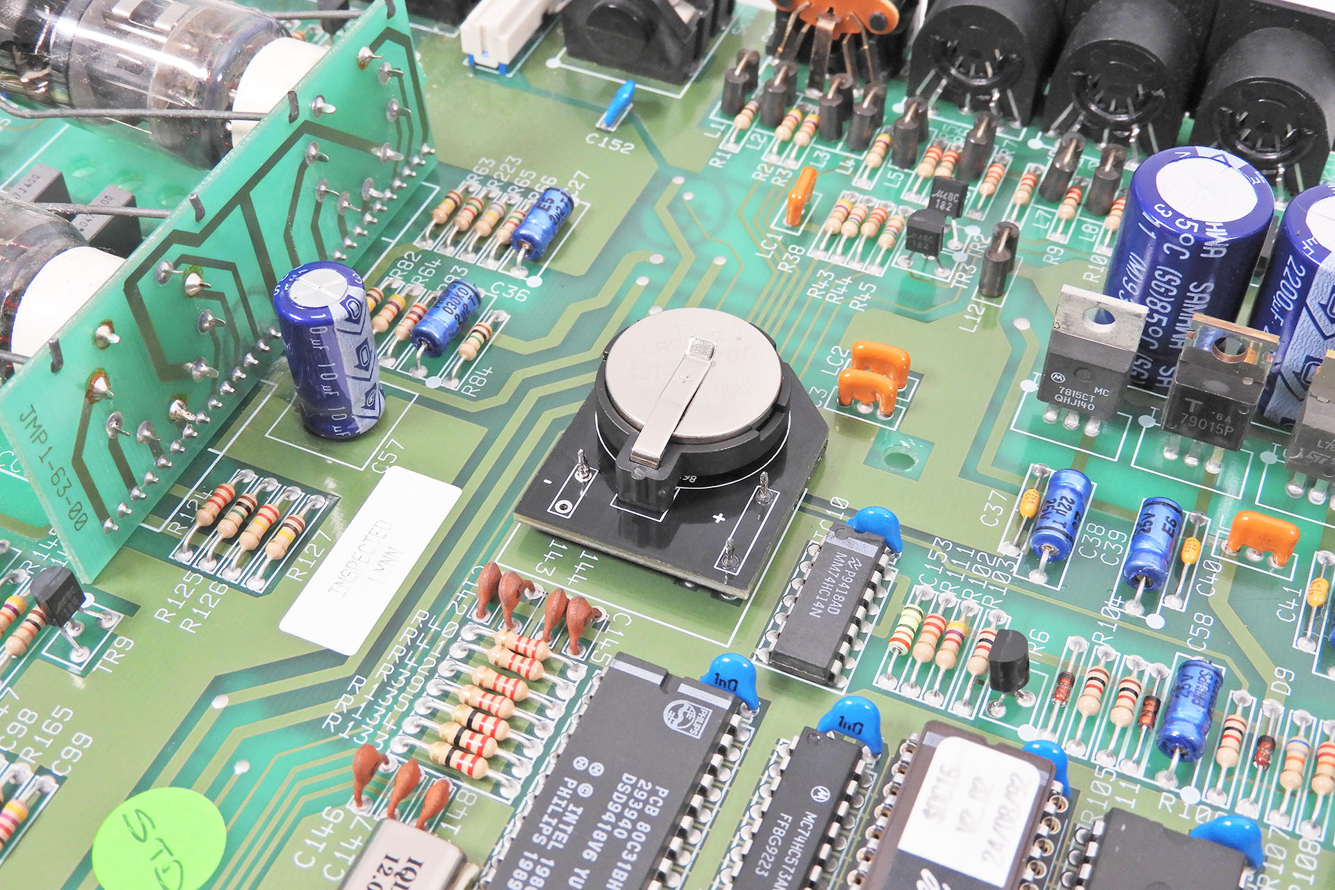
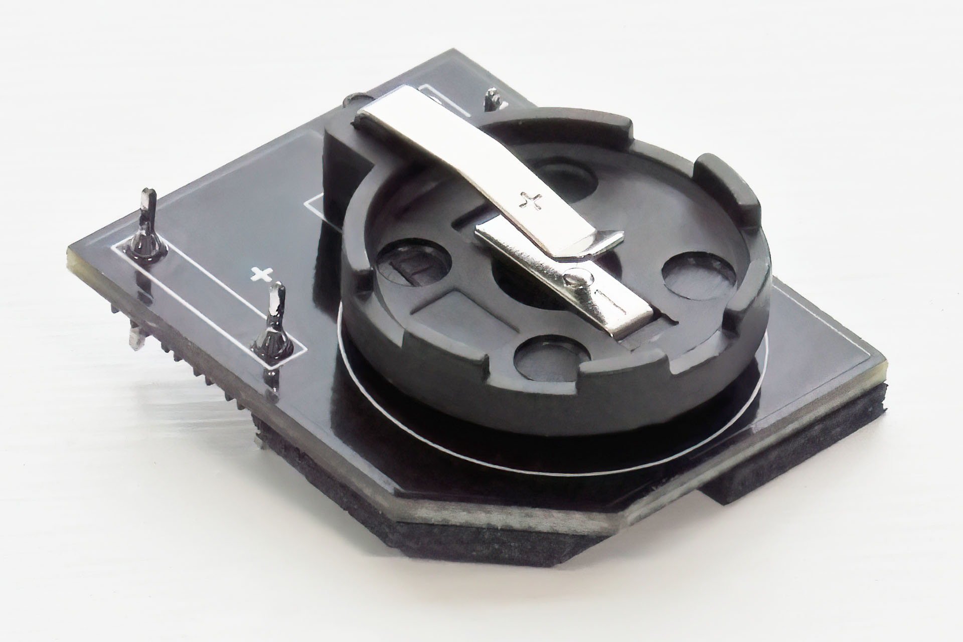
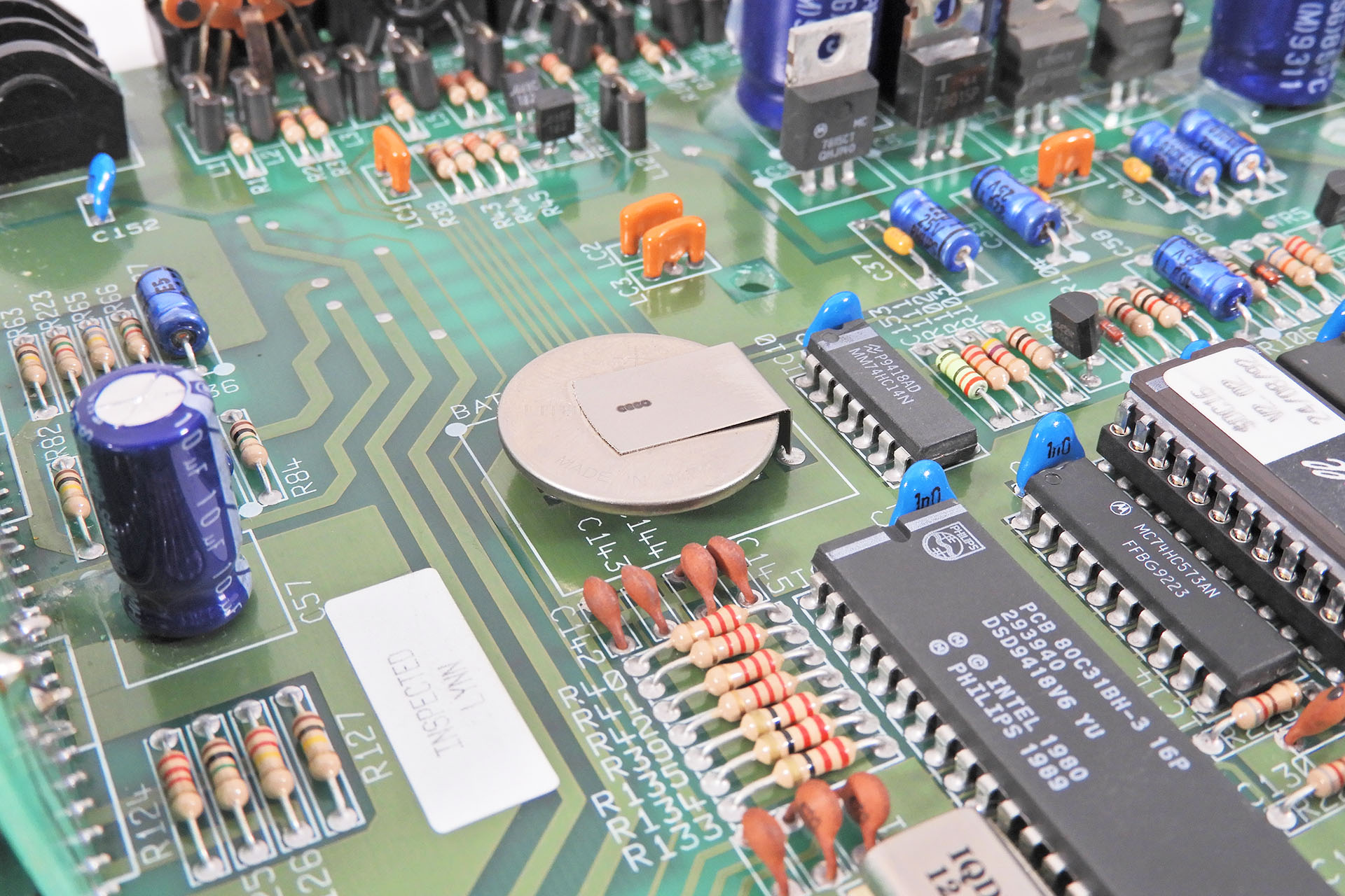
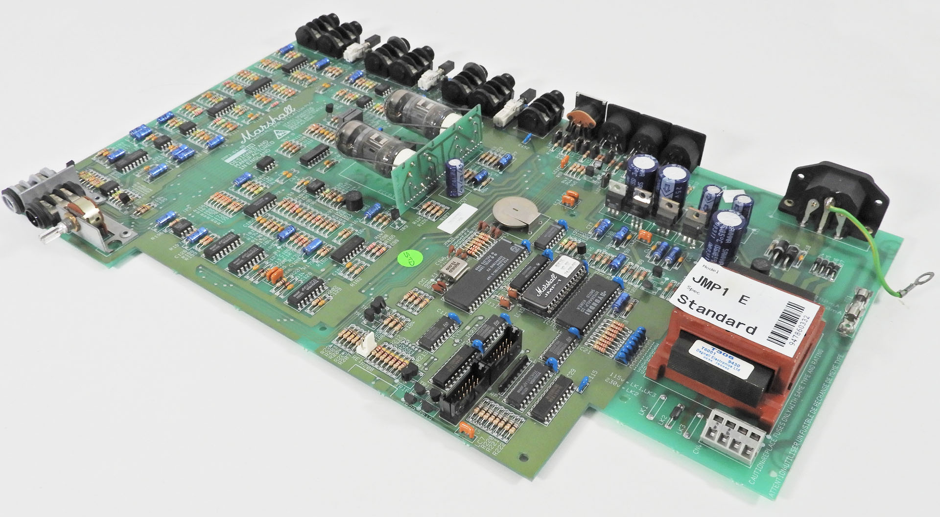
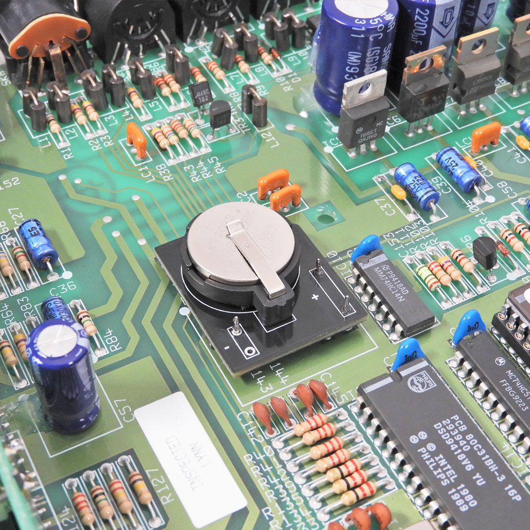
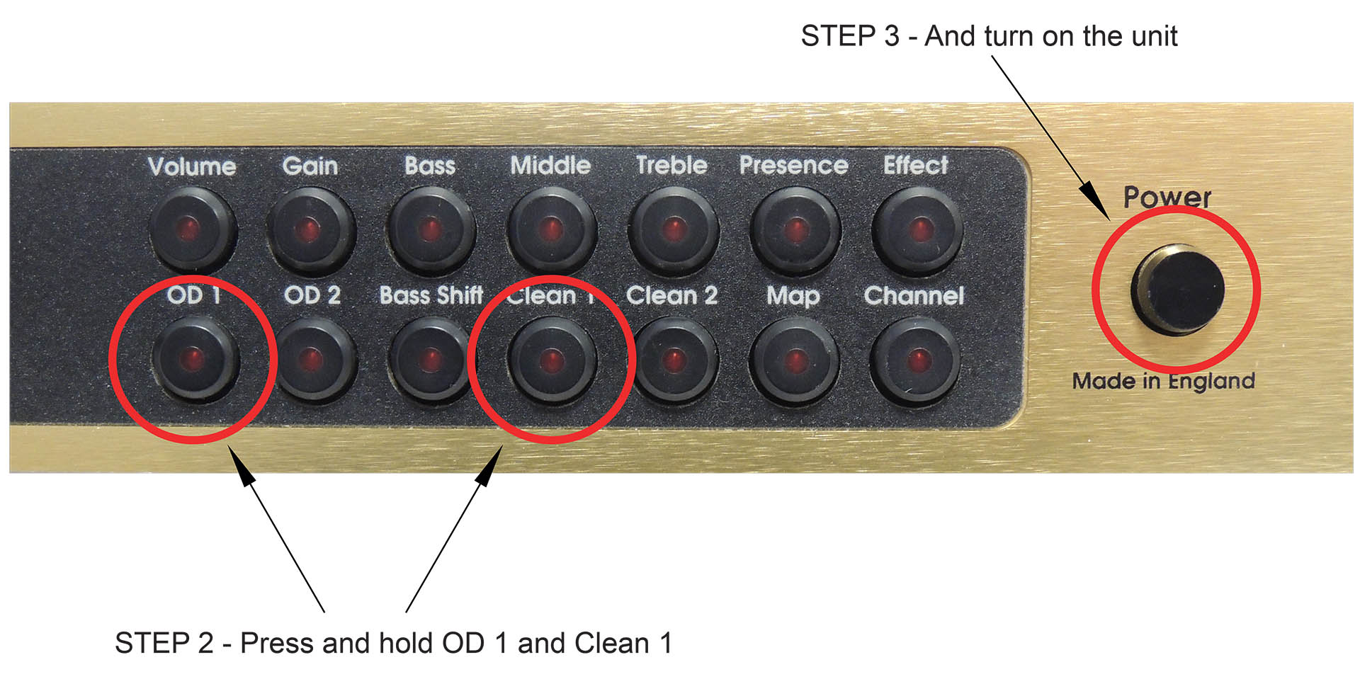
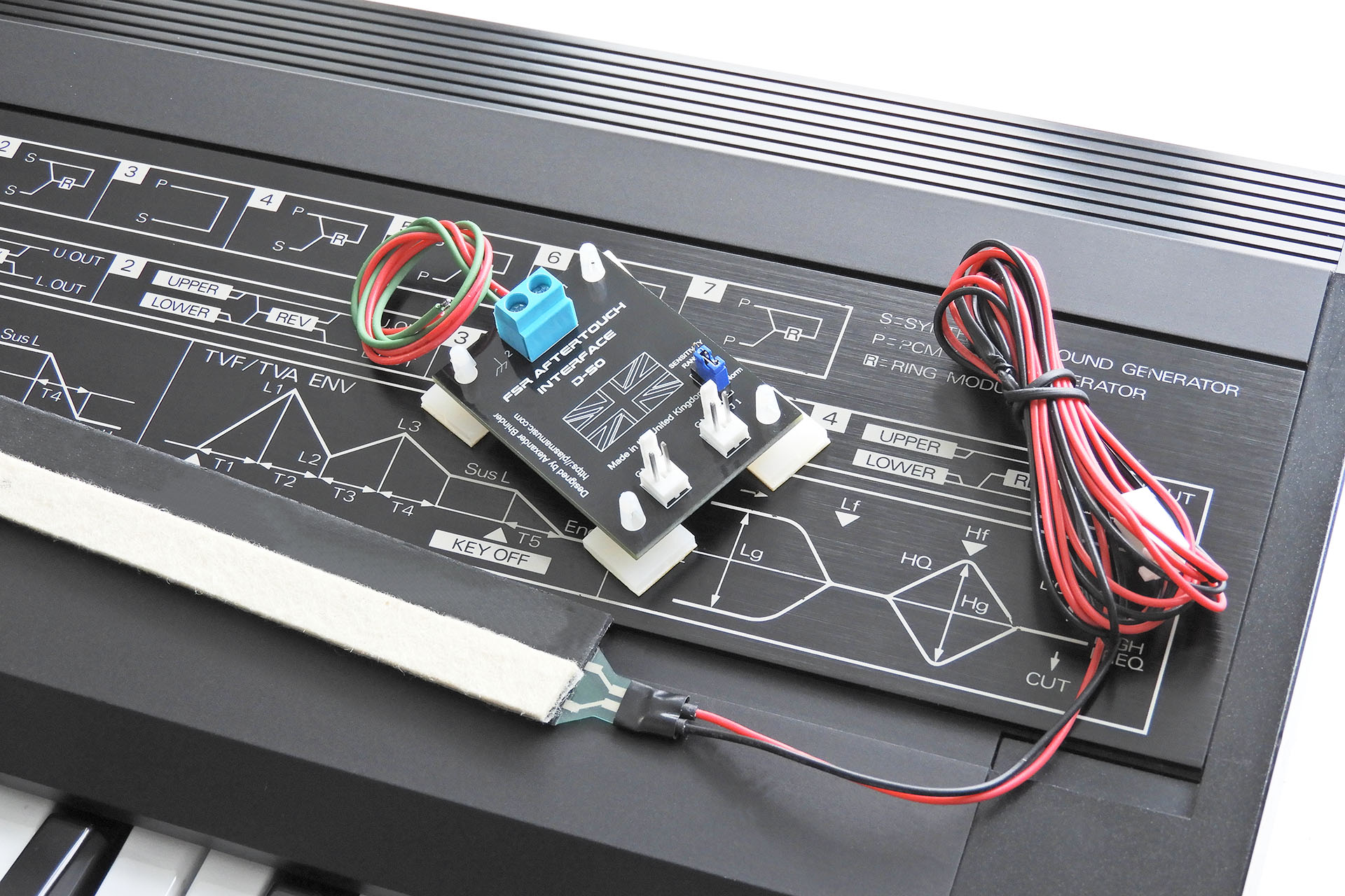
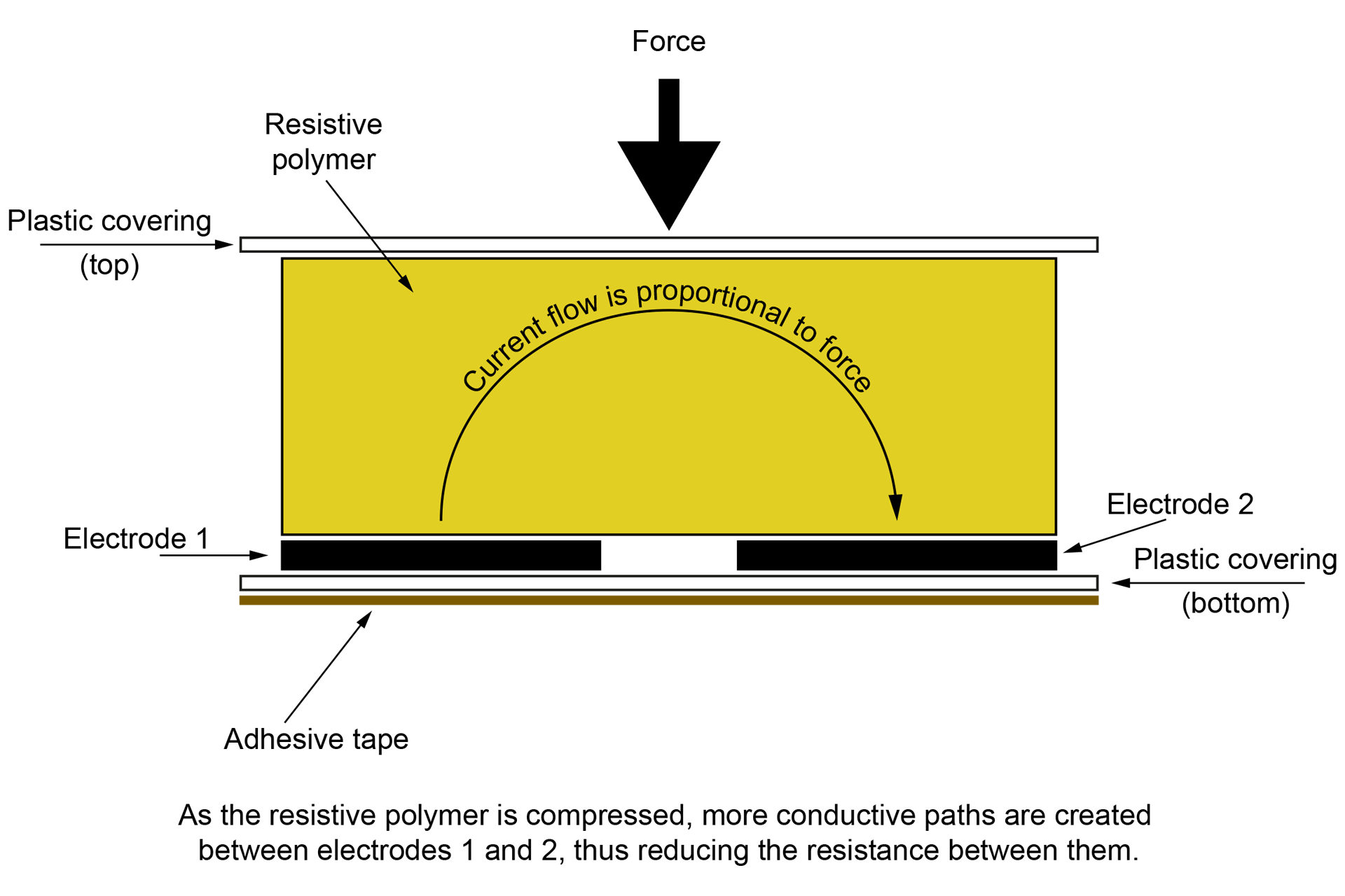
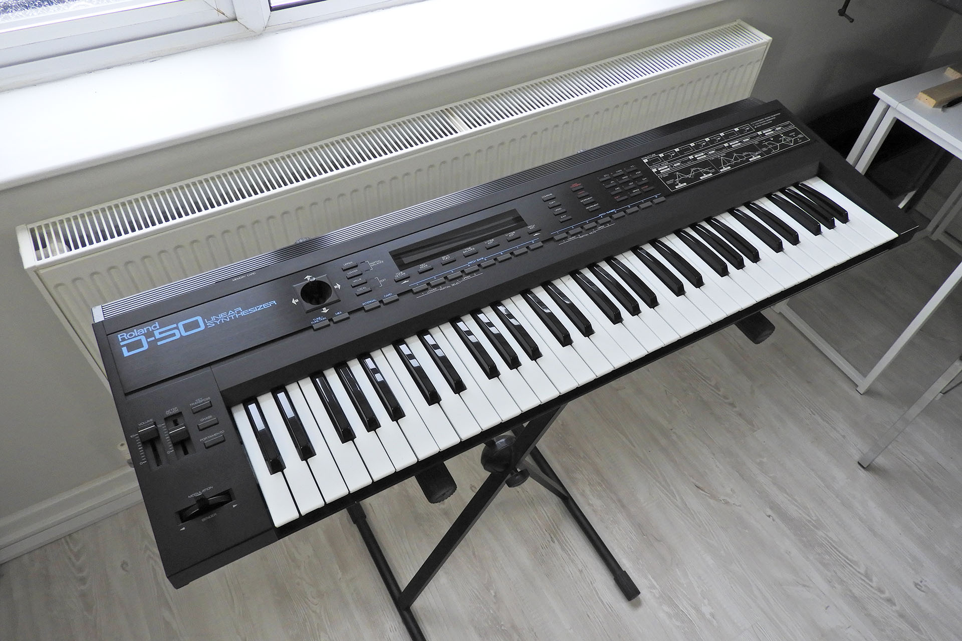
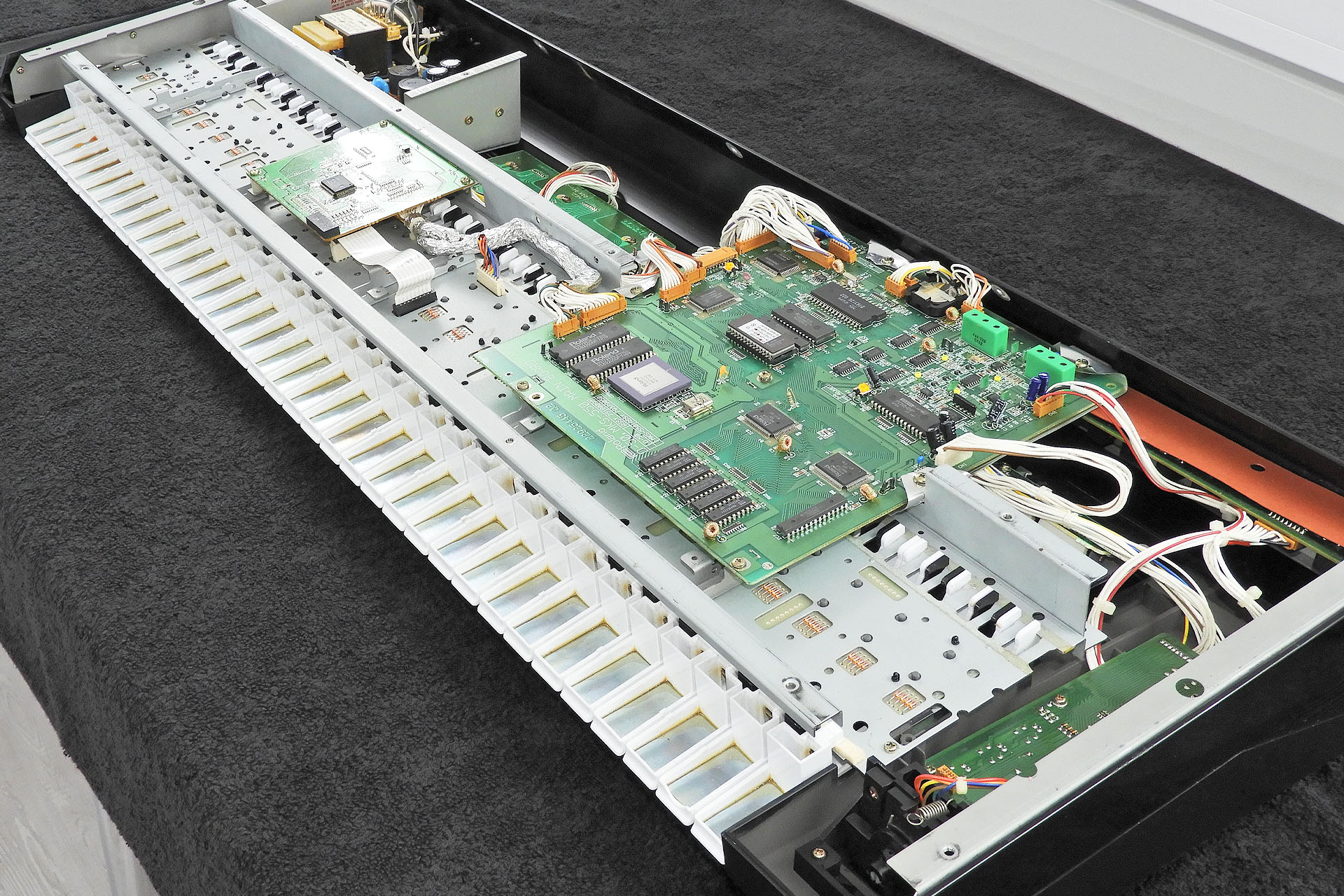
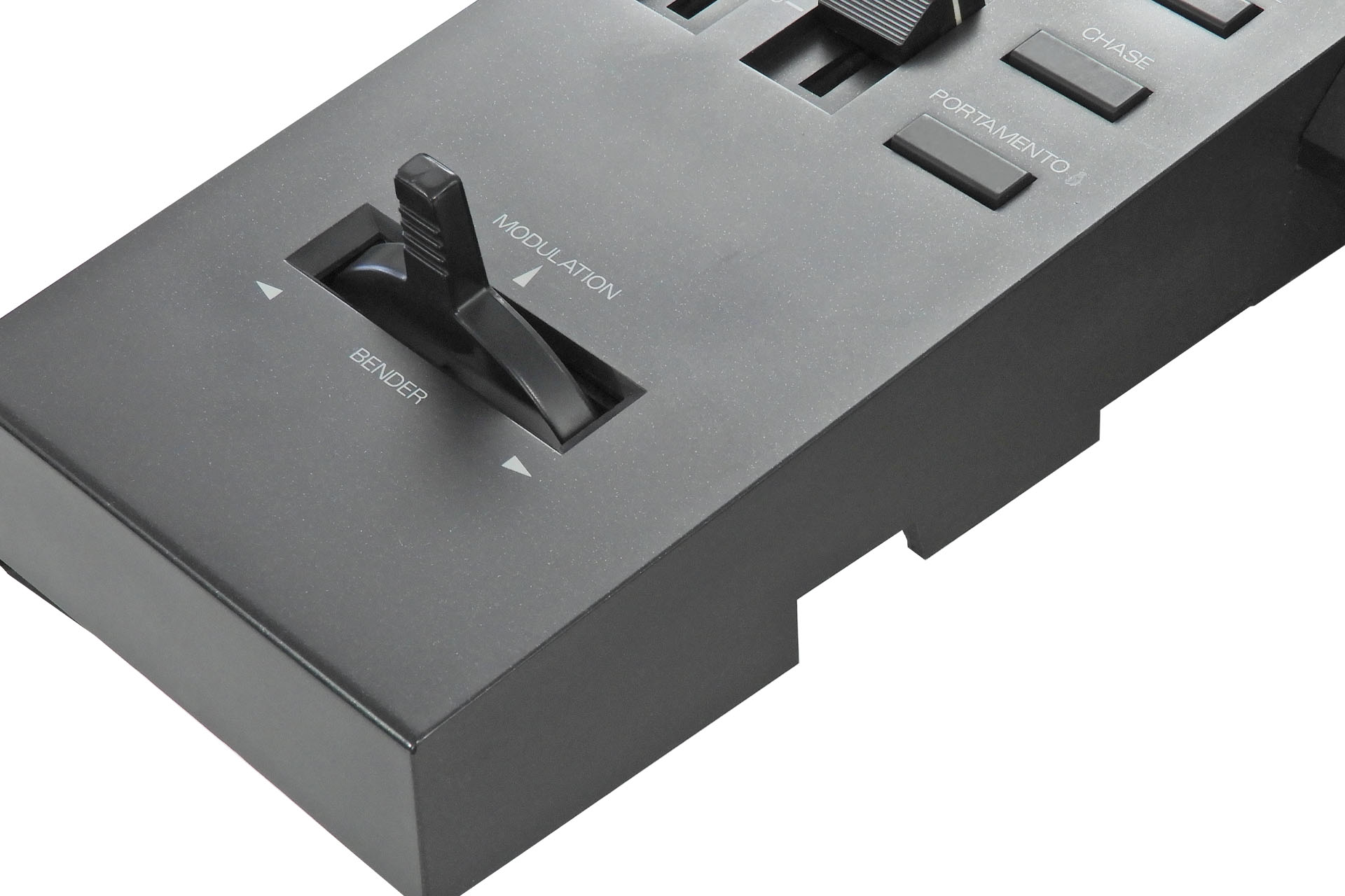
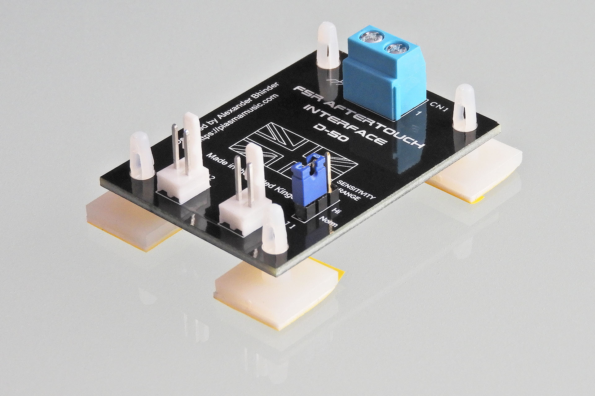
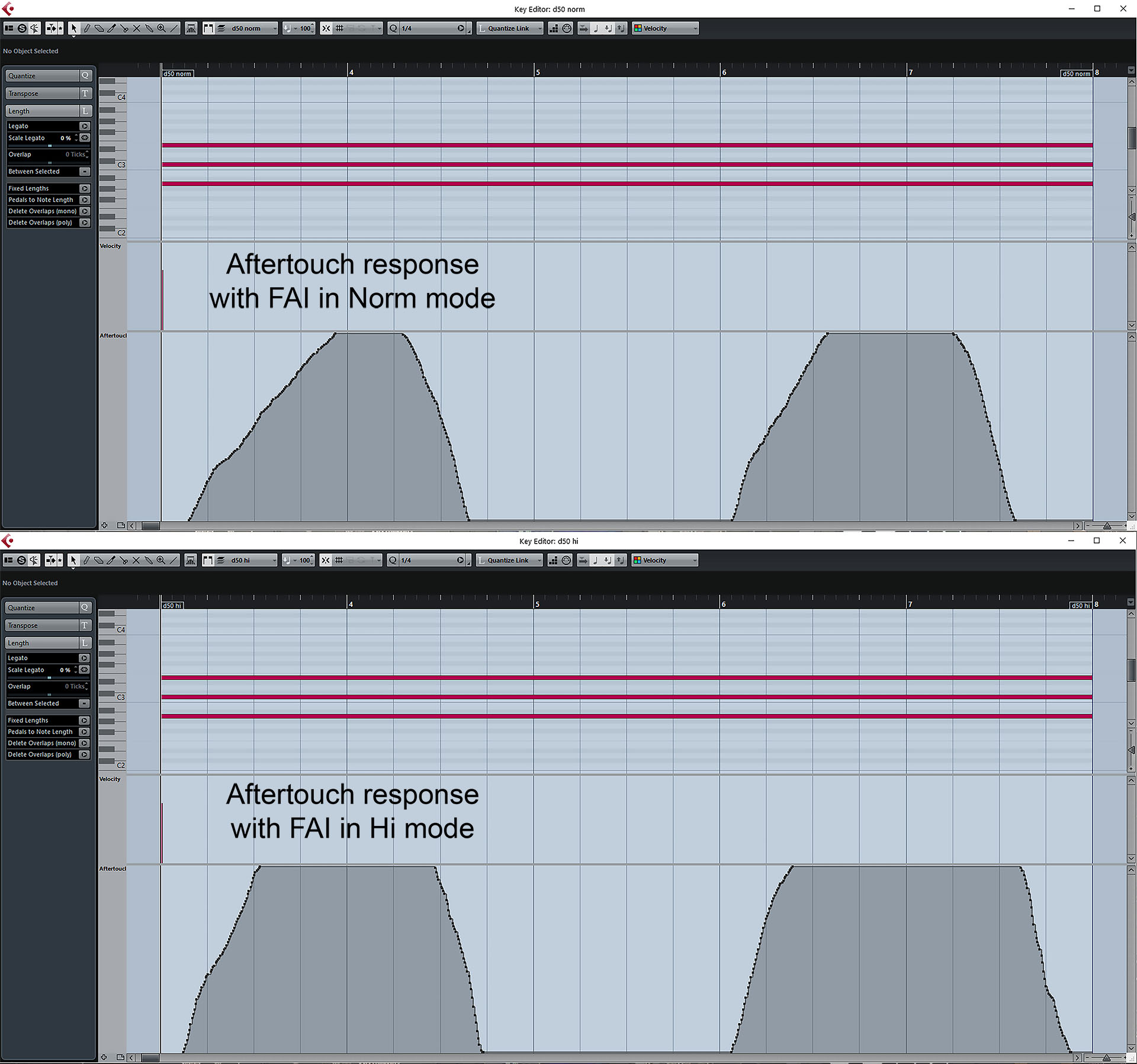
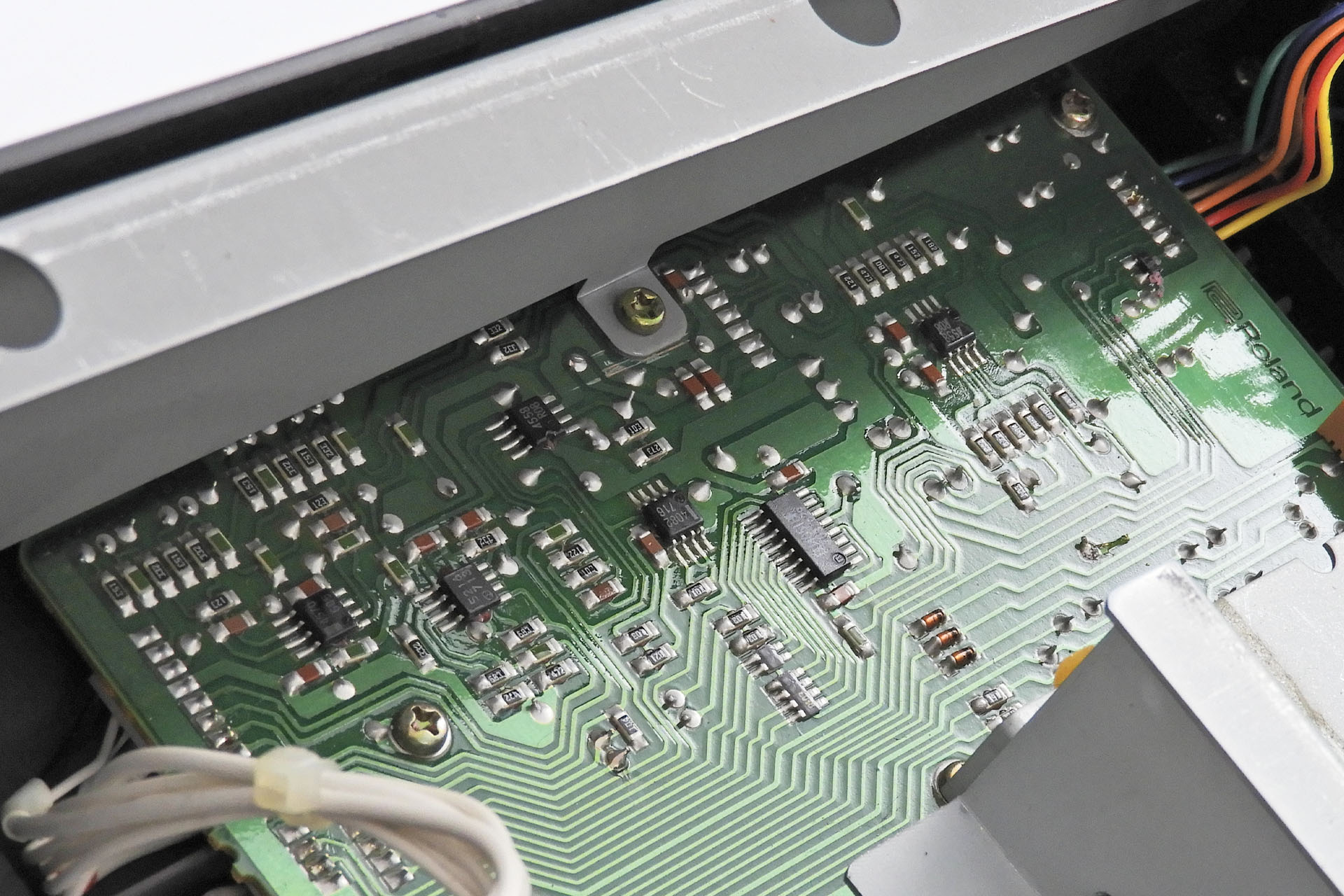
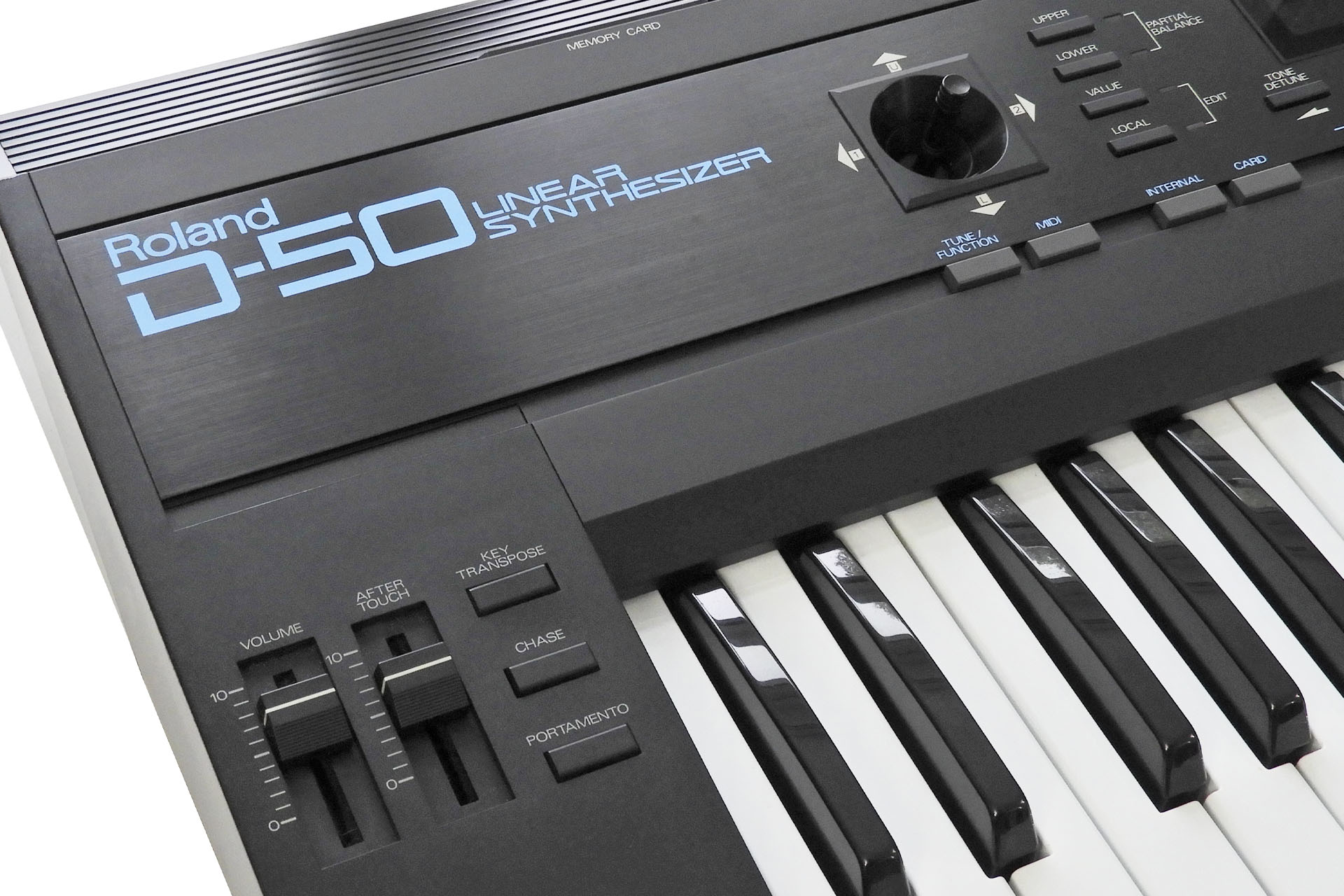

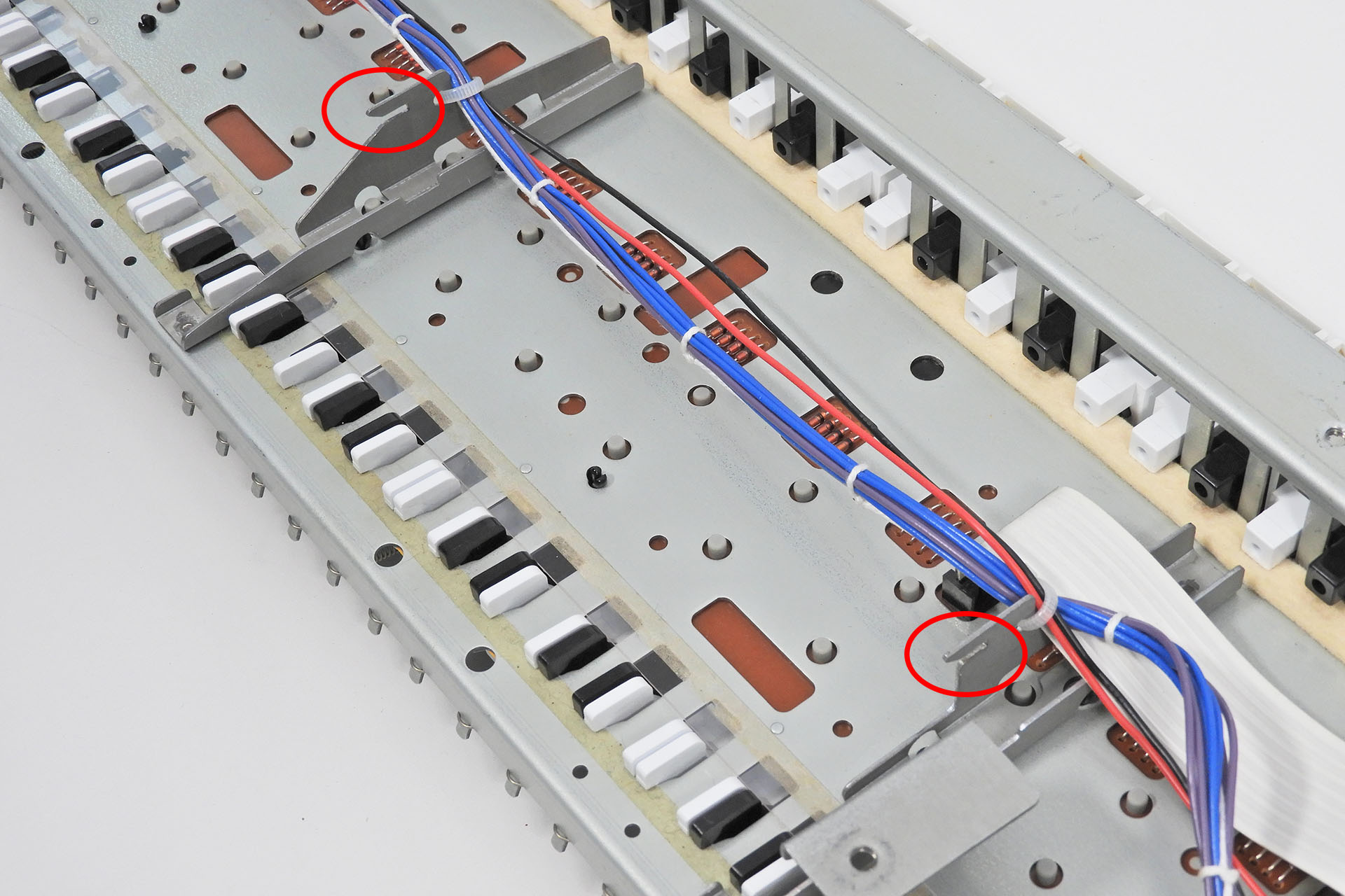
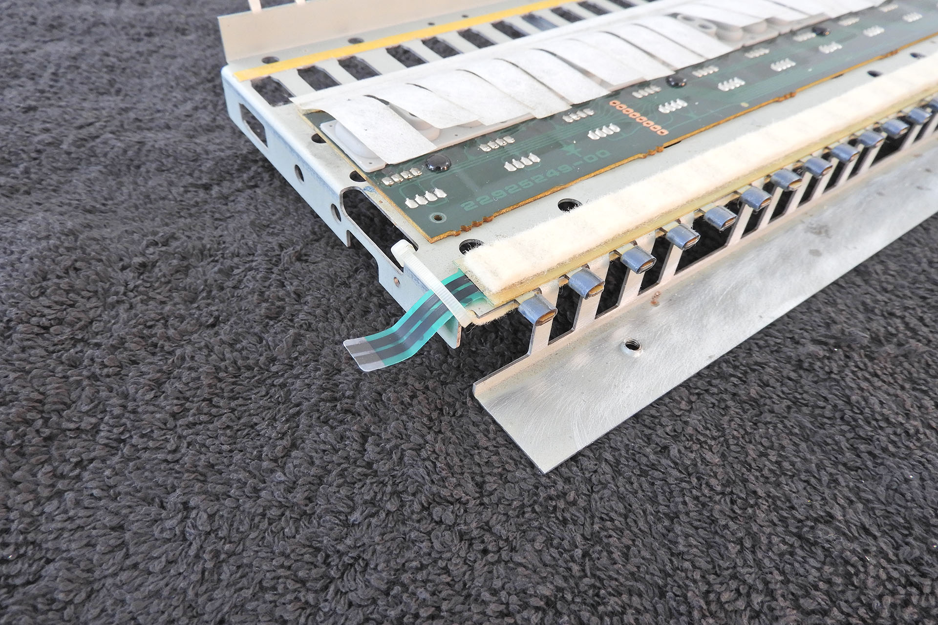
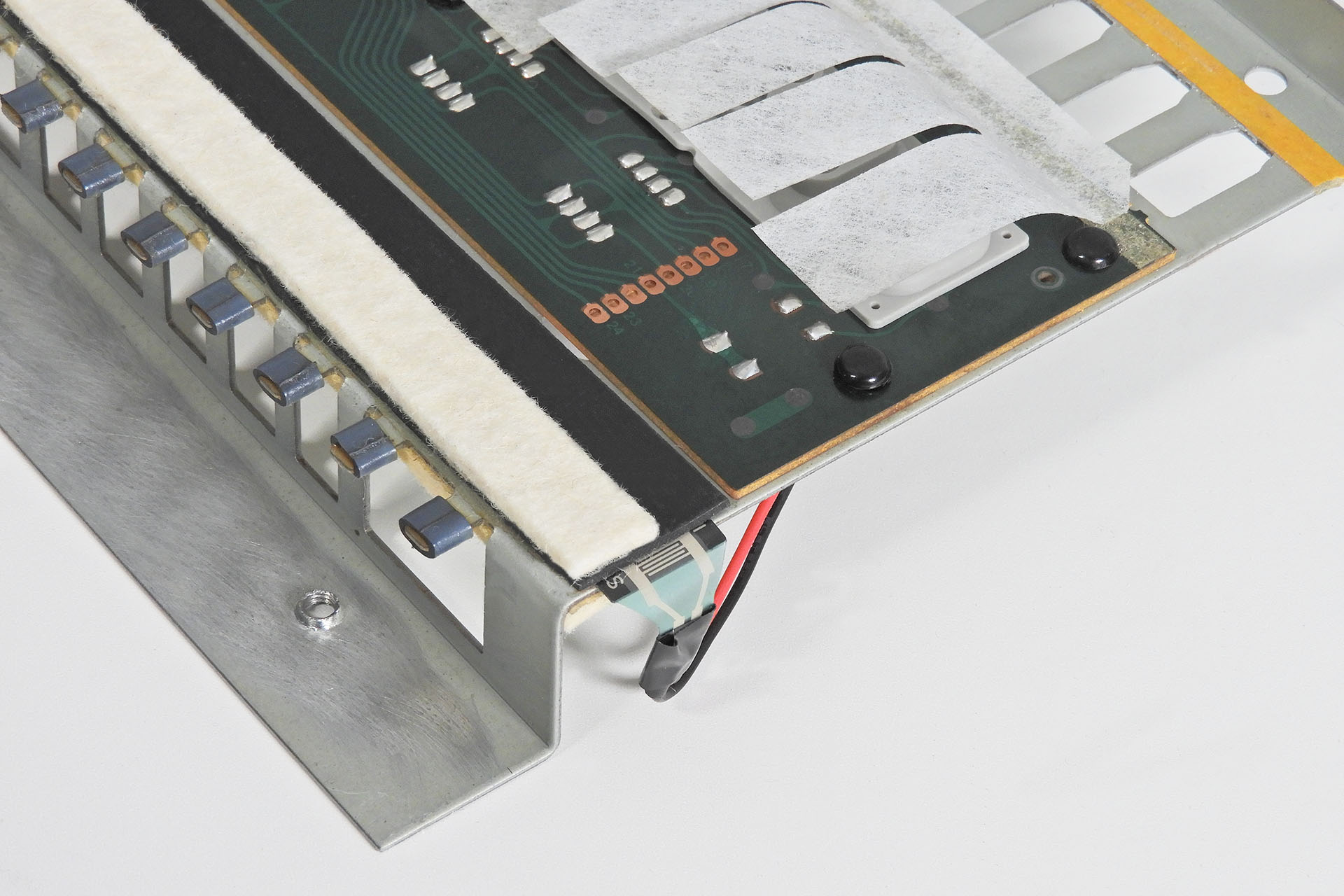
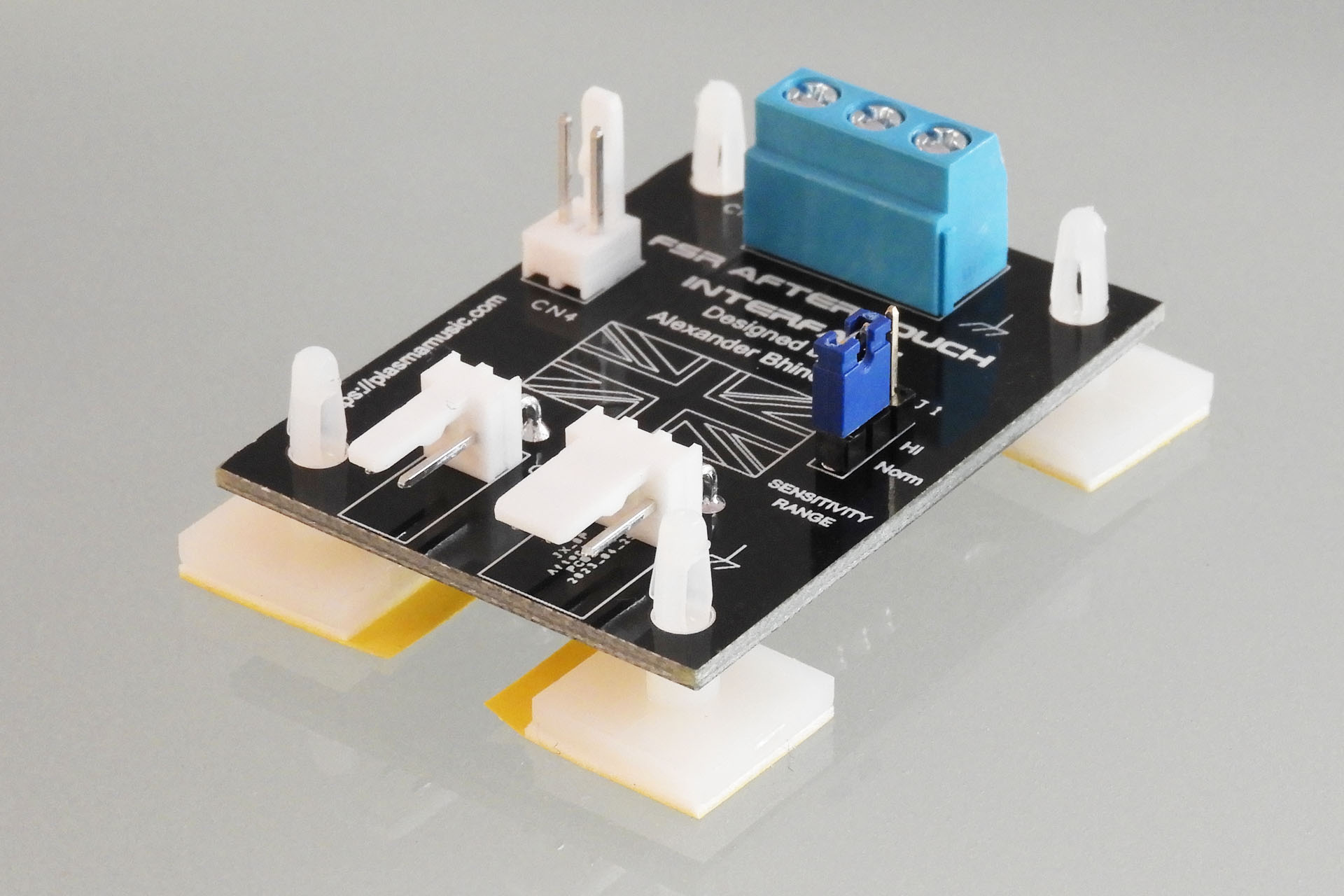
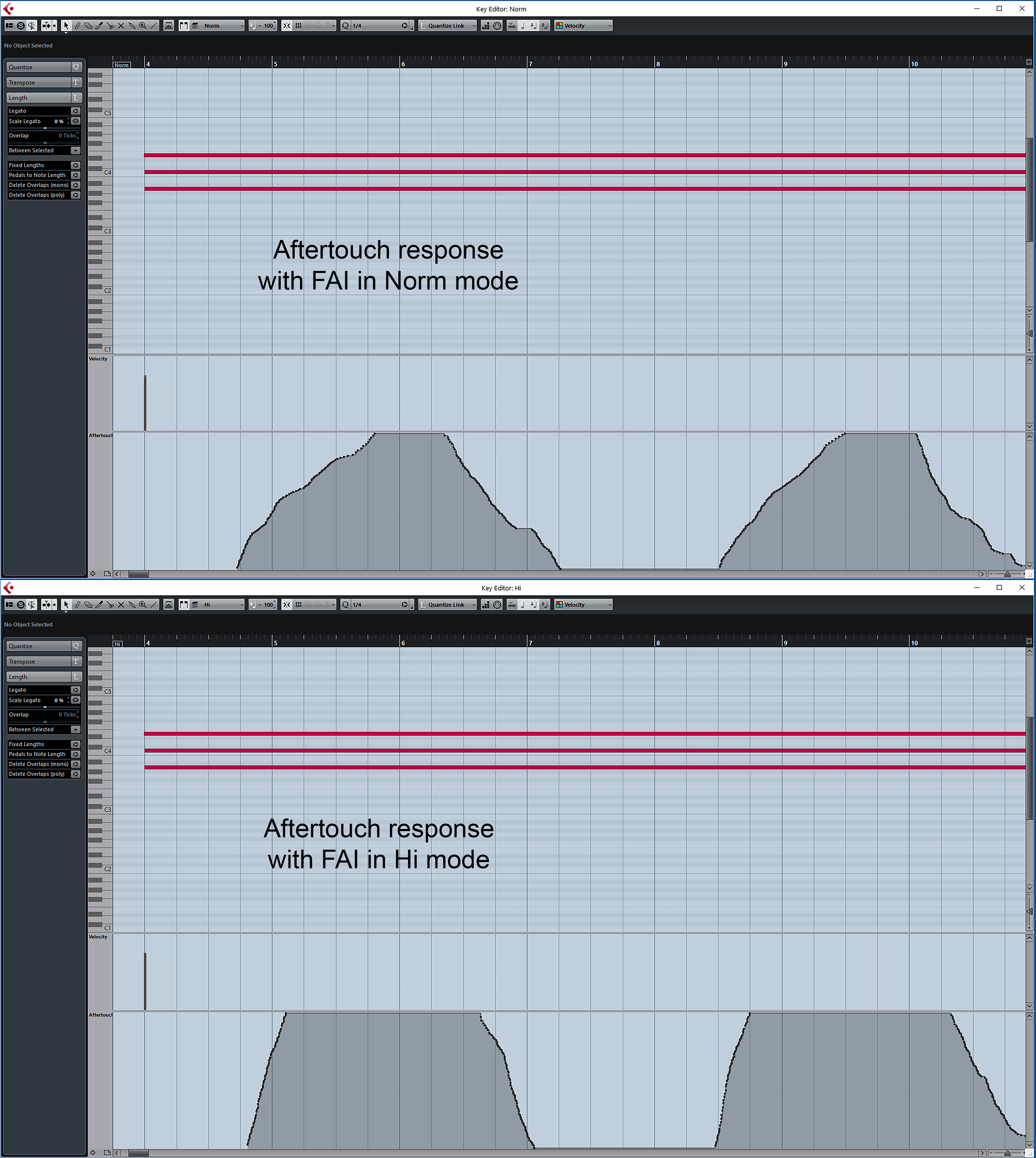
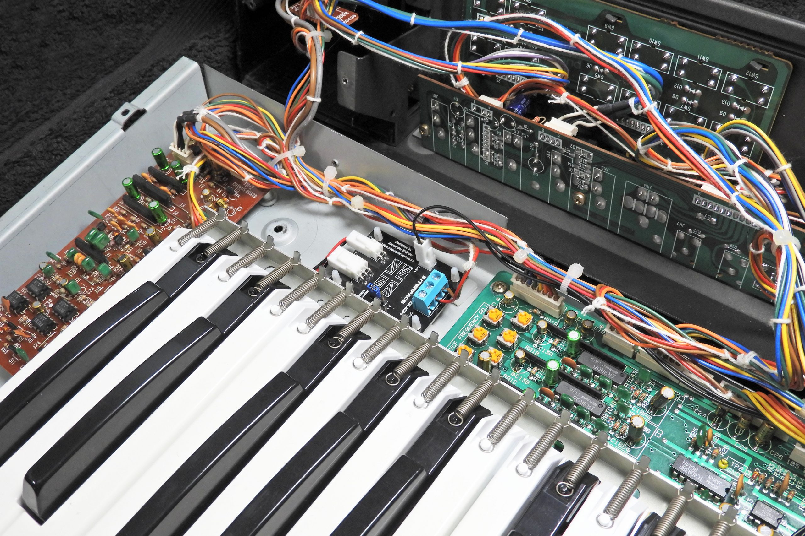
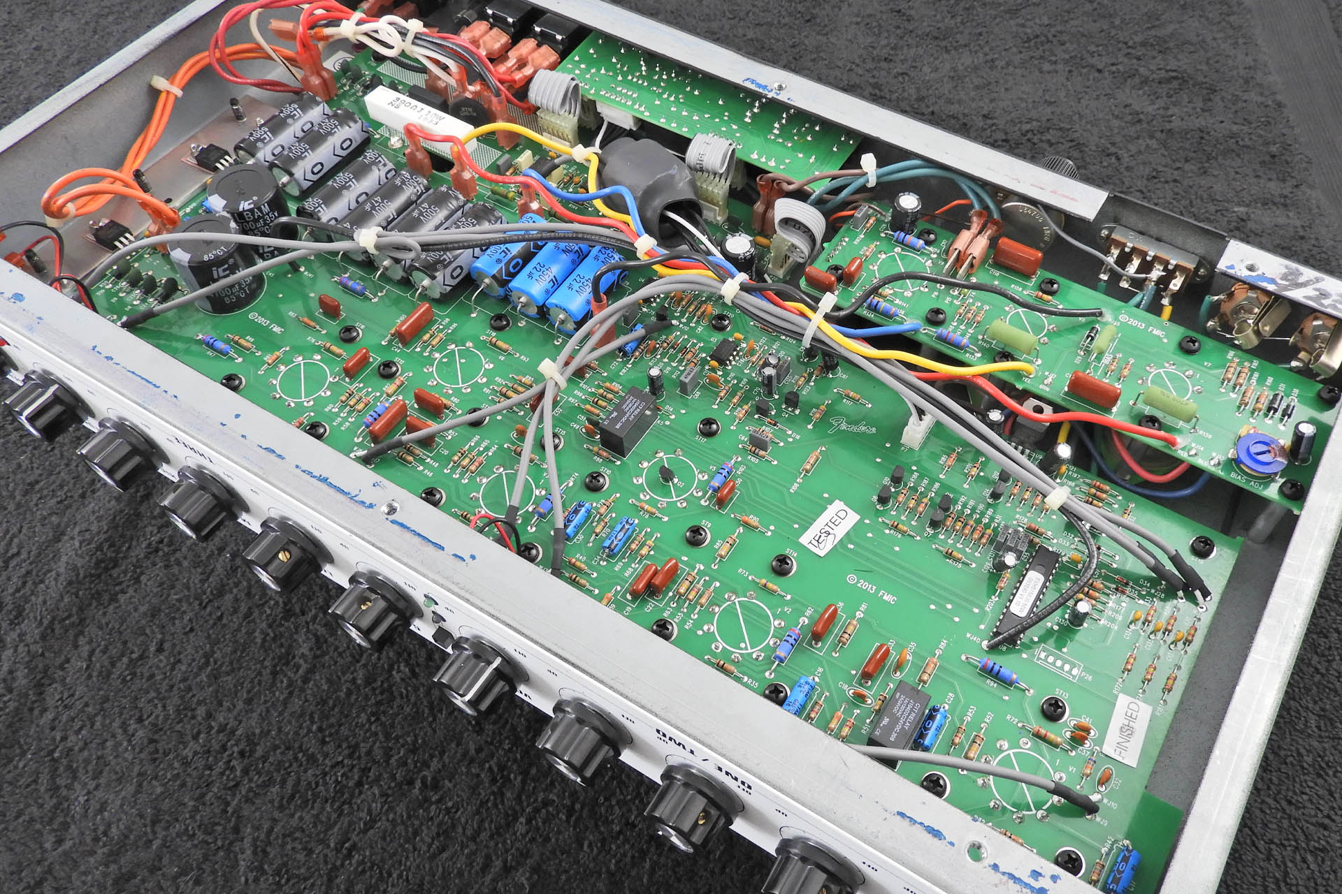
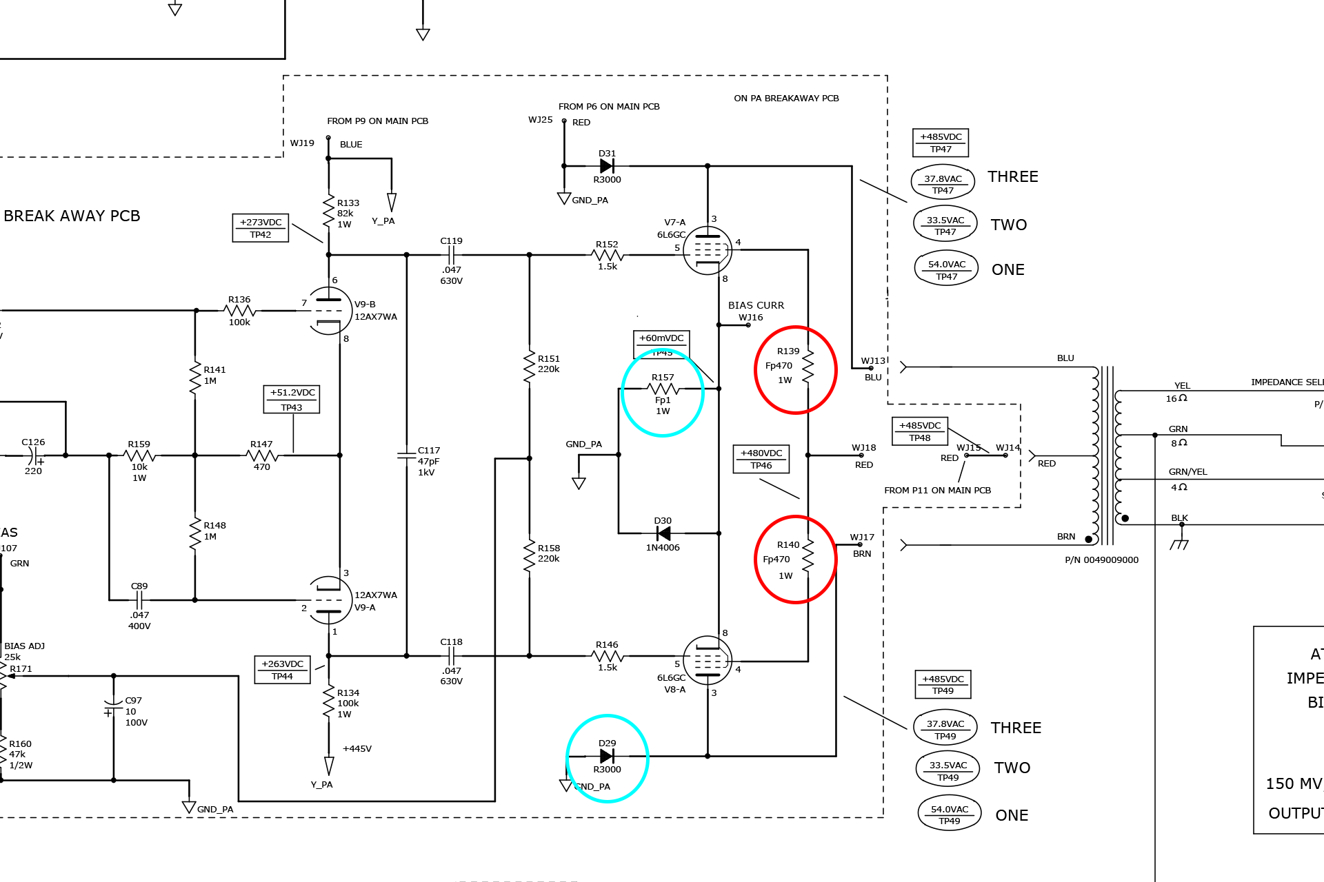
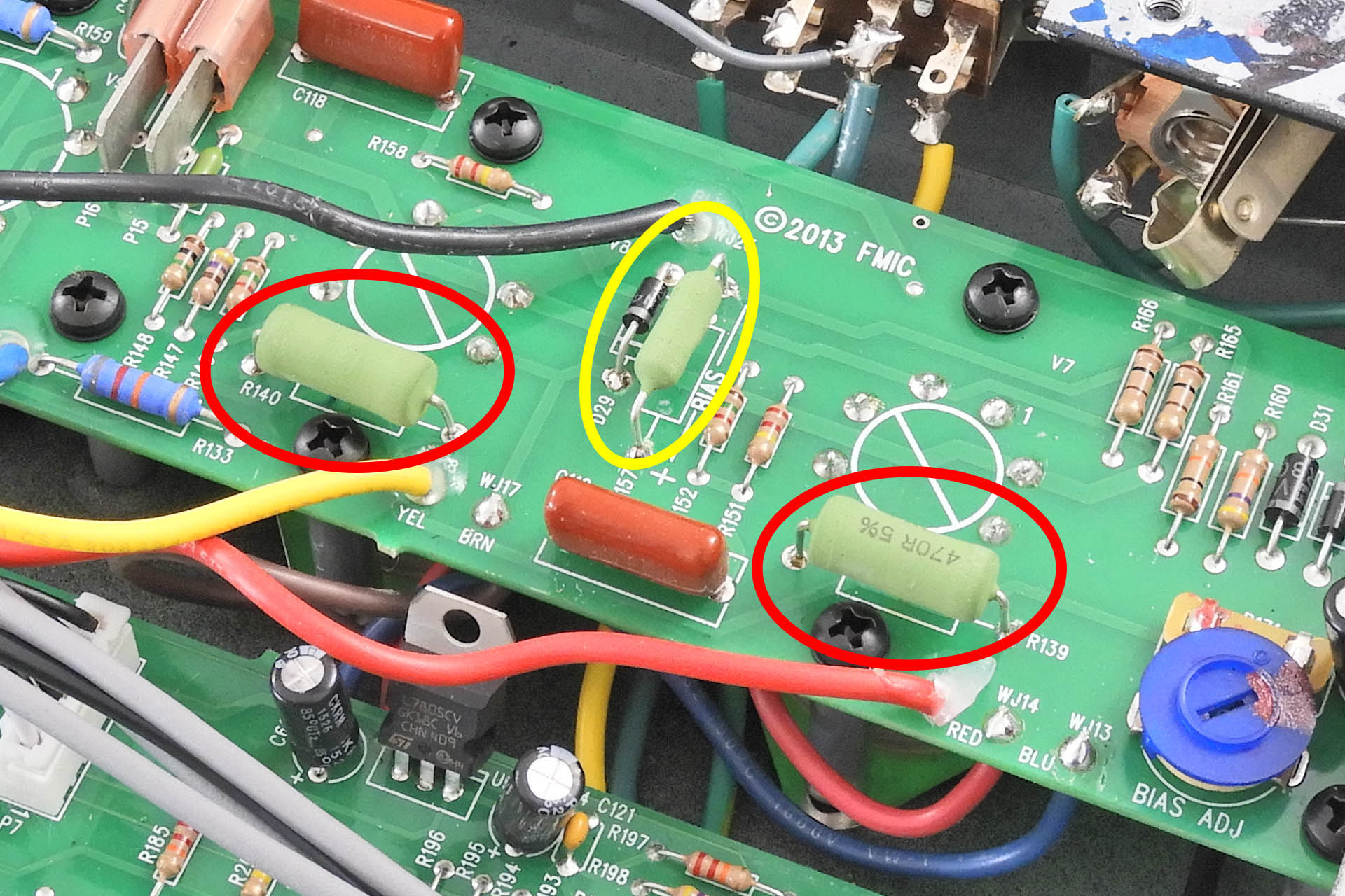
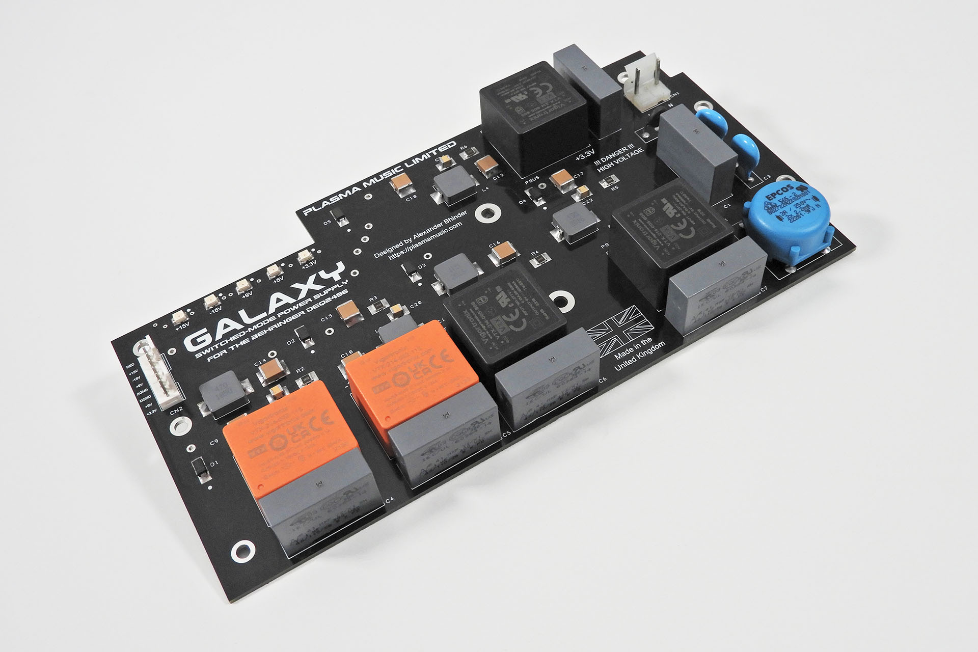
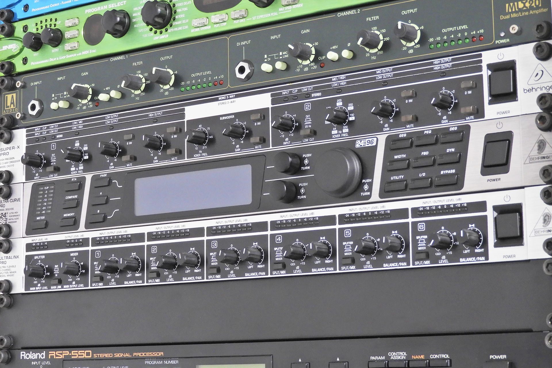
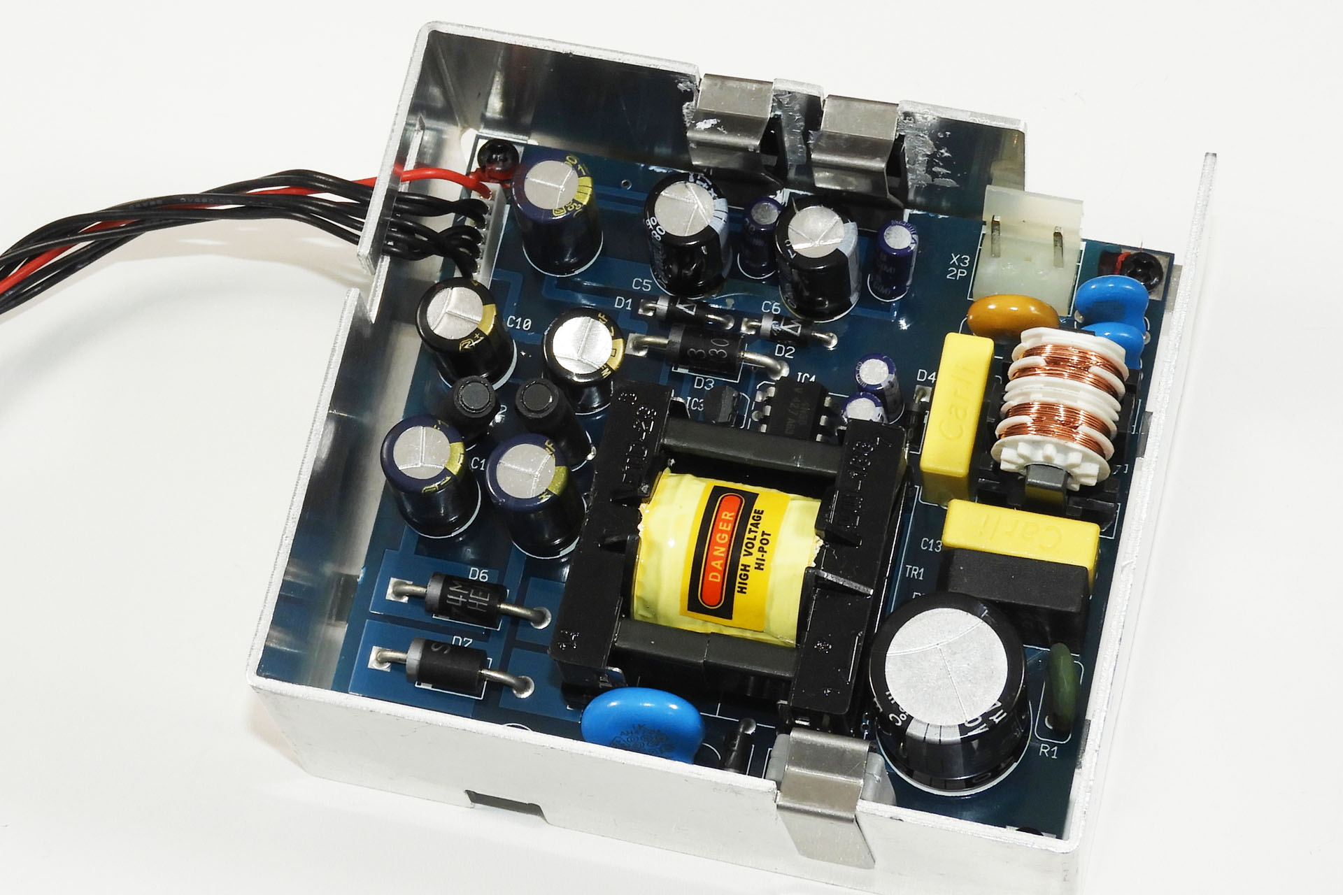
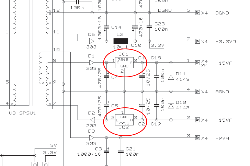
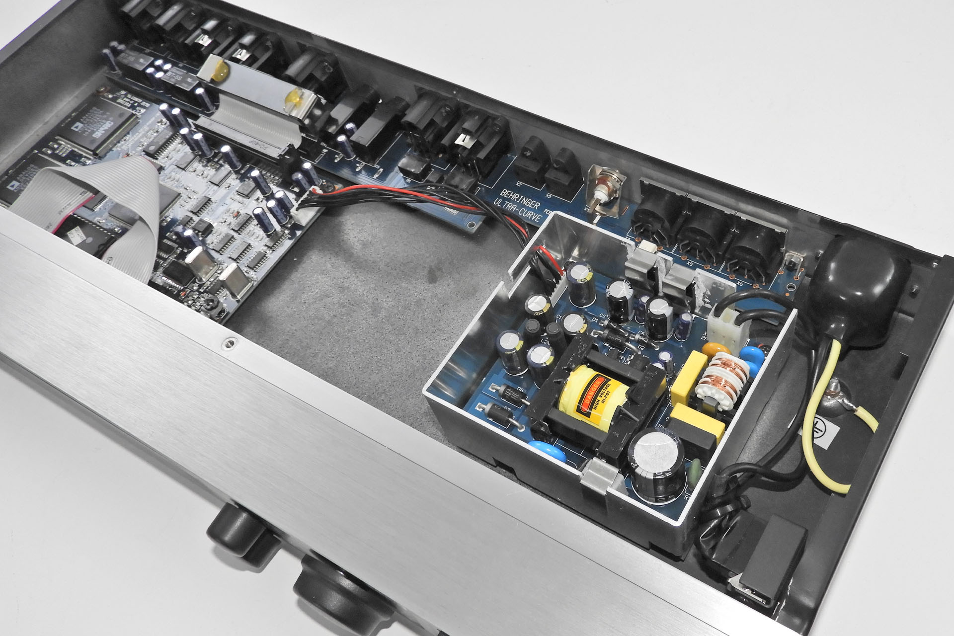
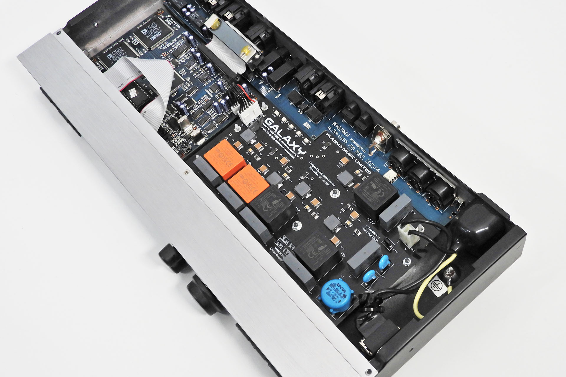
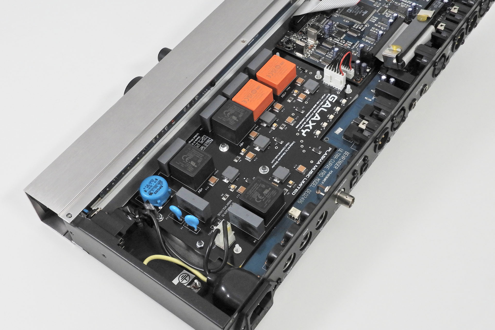
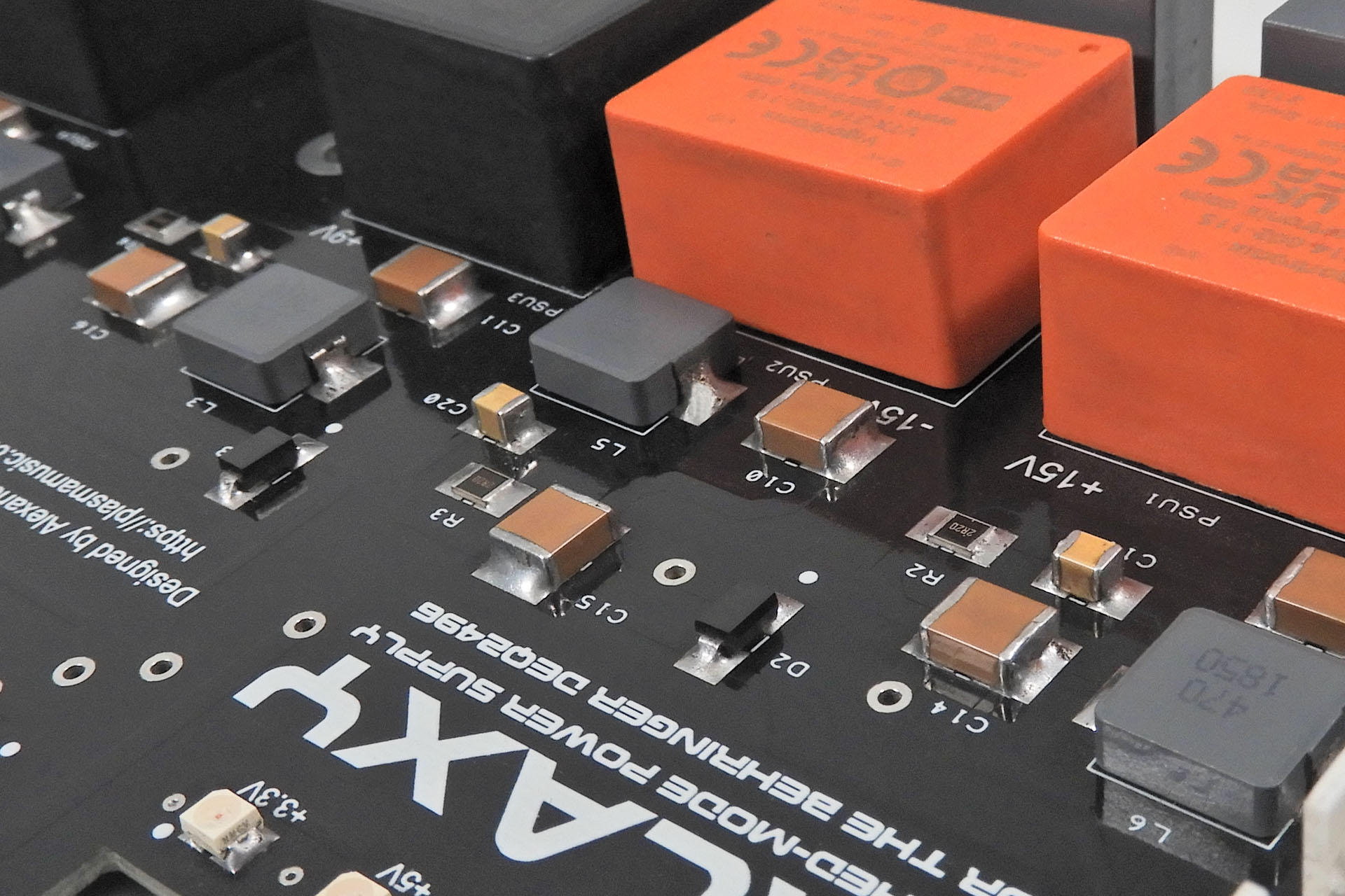

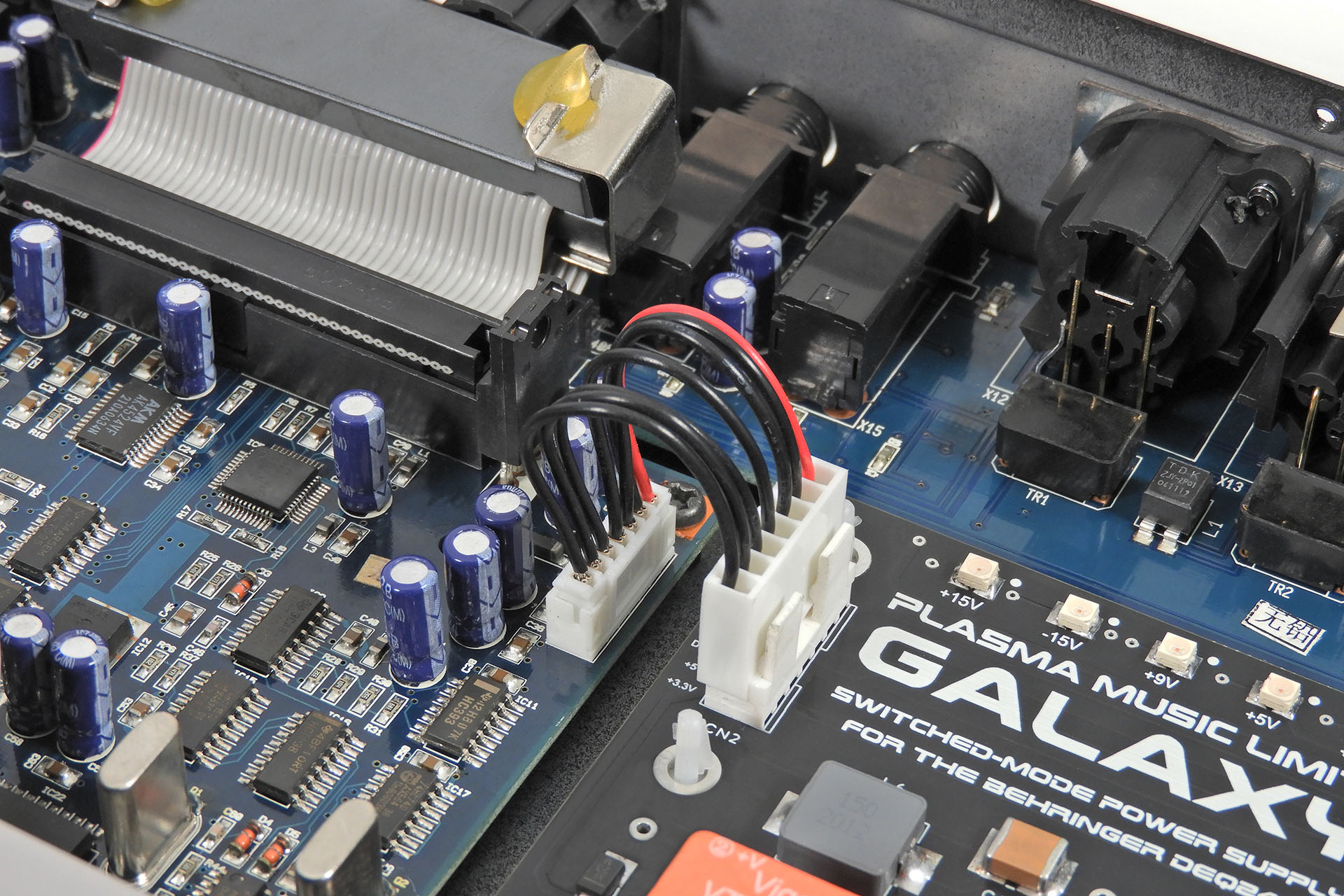
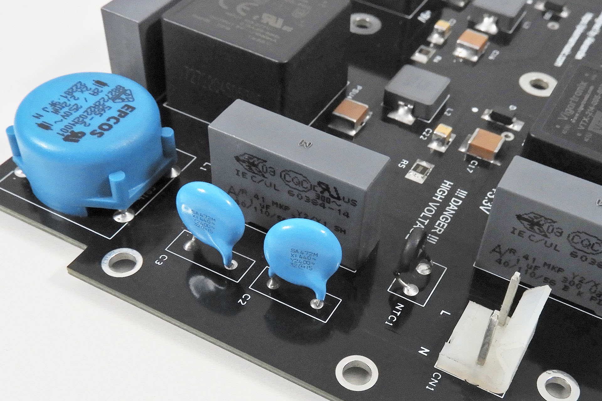
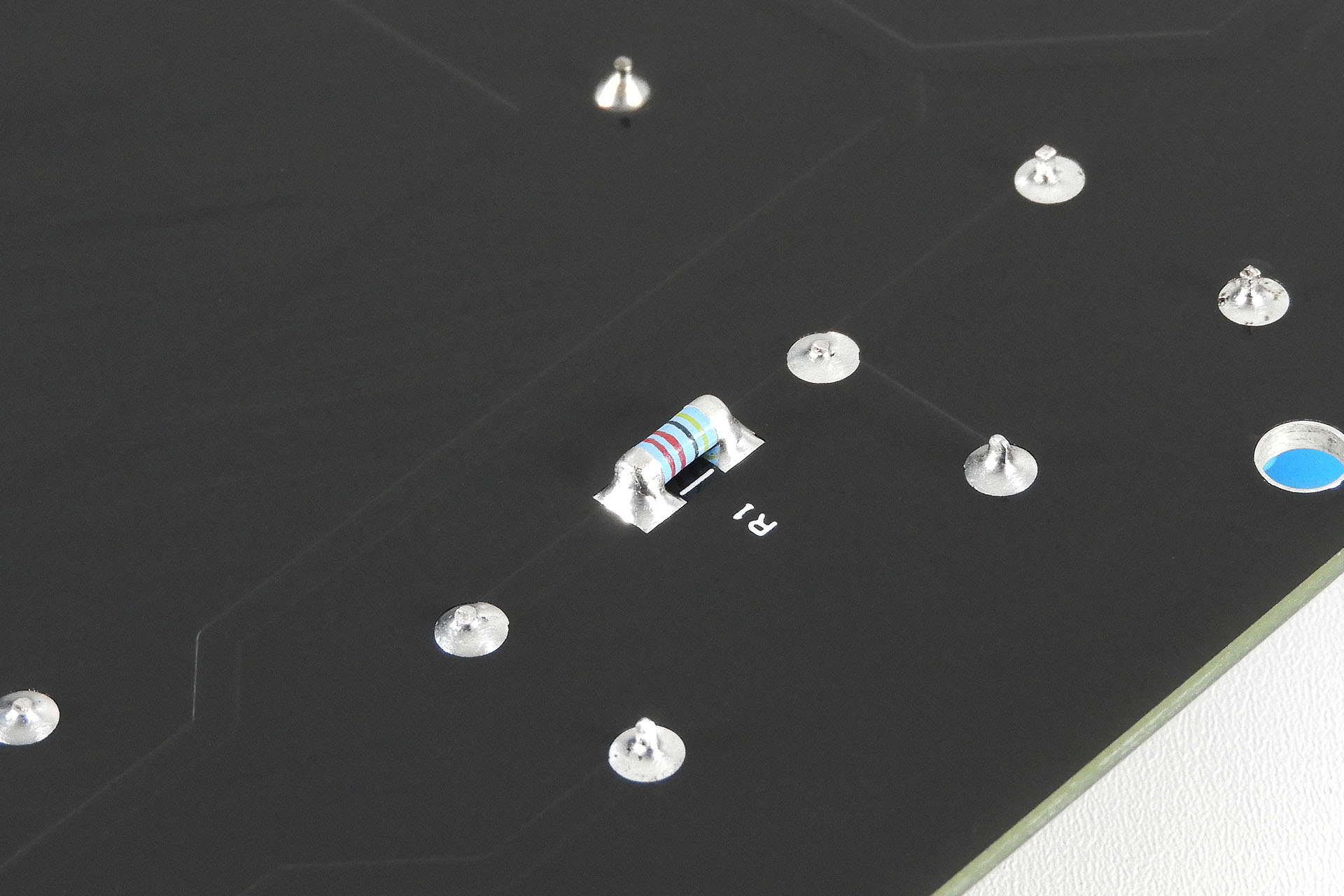

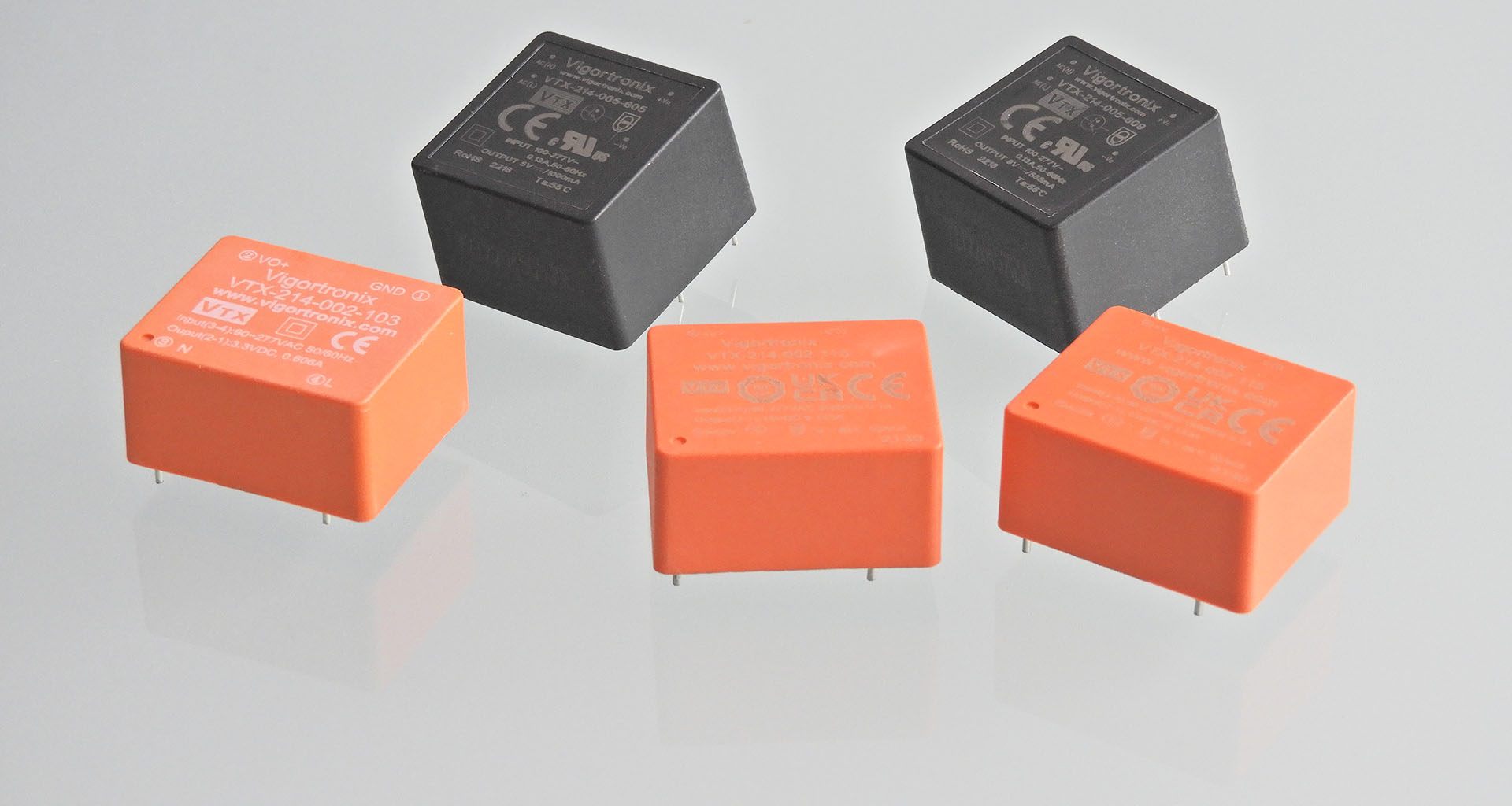
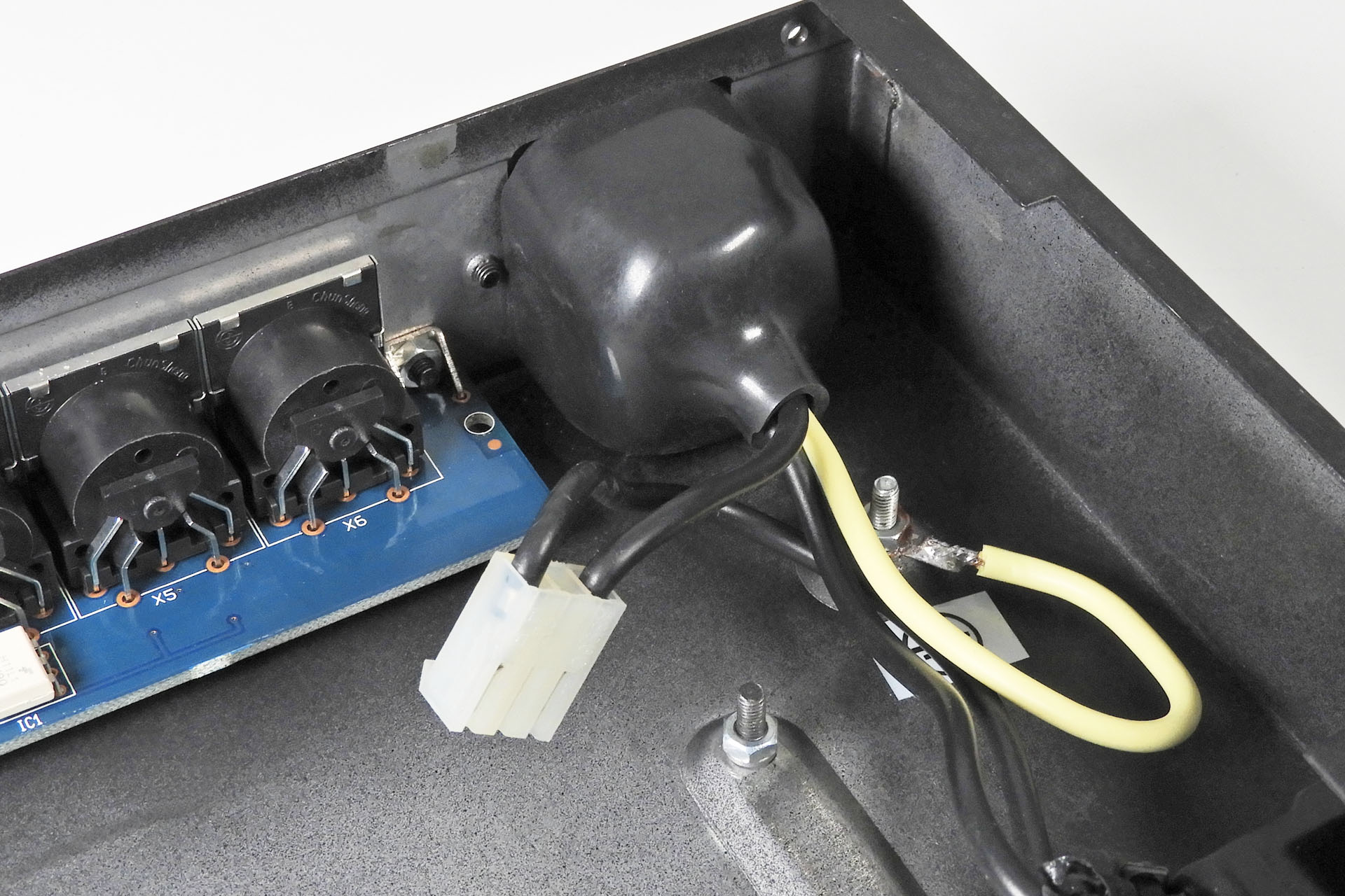
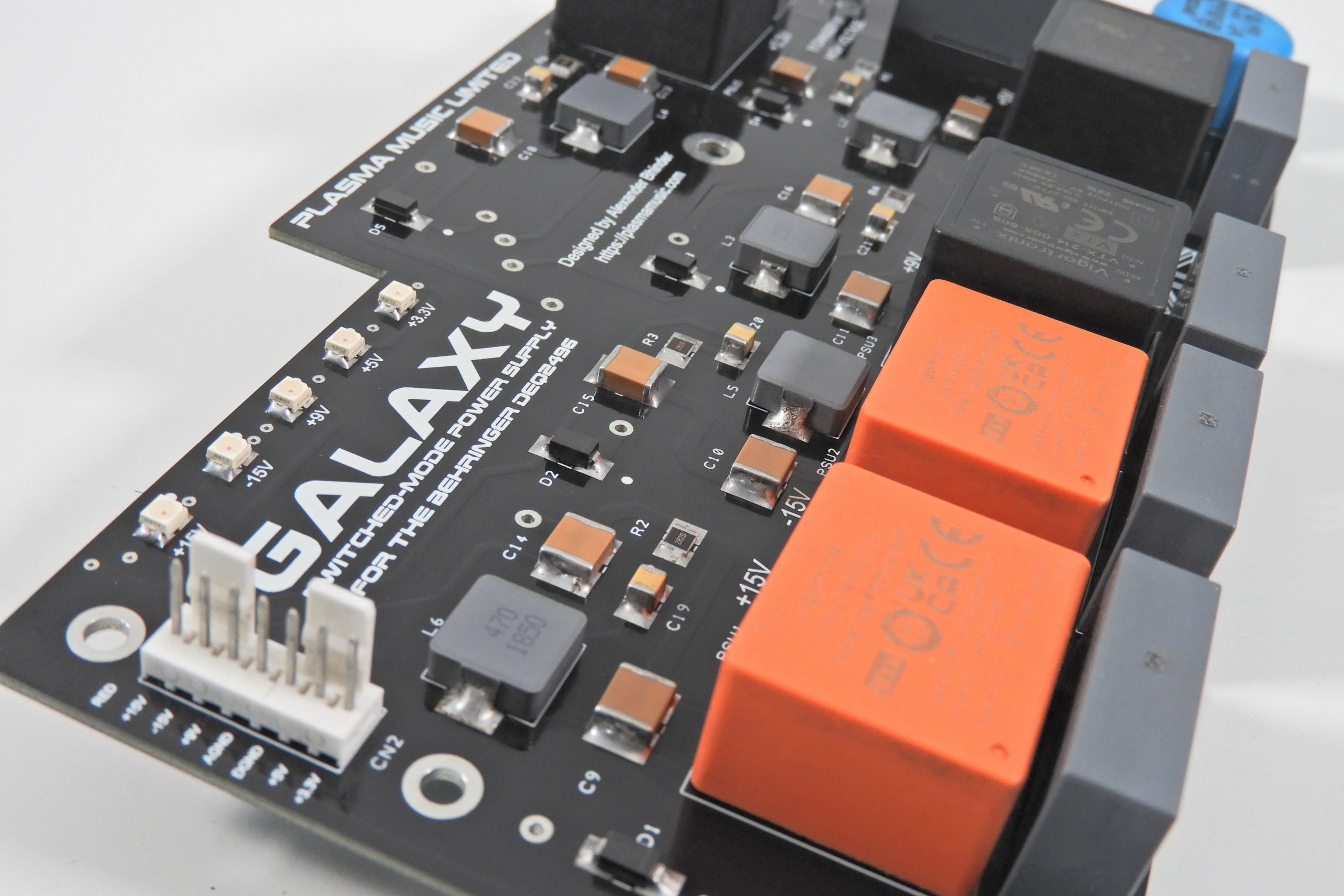
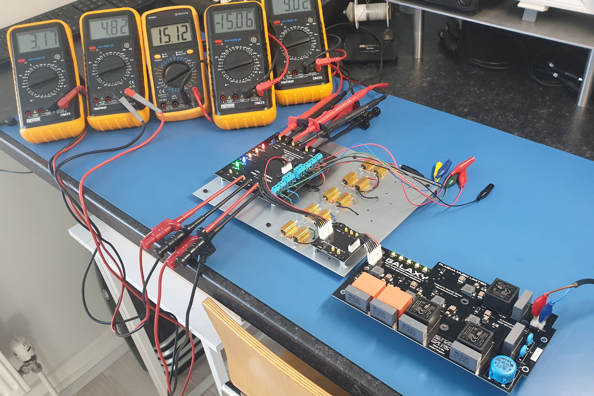
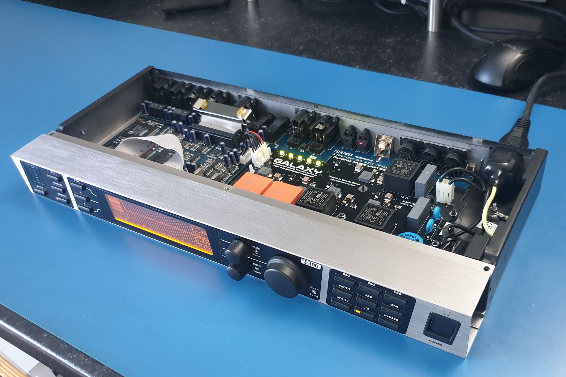
 I'm deeply concerned about the environment and the exploitation of labour and so I always use local manufacturers in preference to the Far East, with the following in mind: