
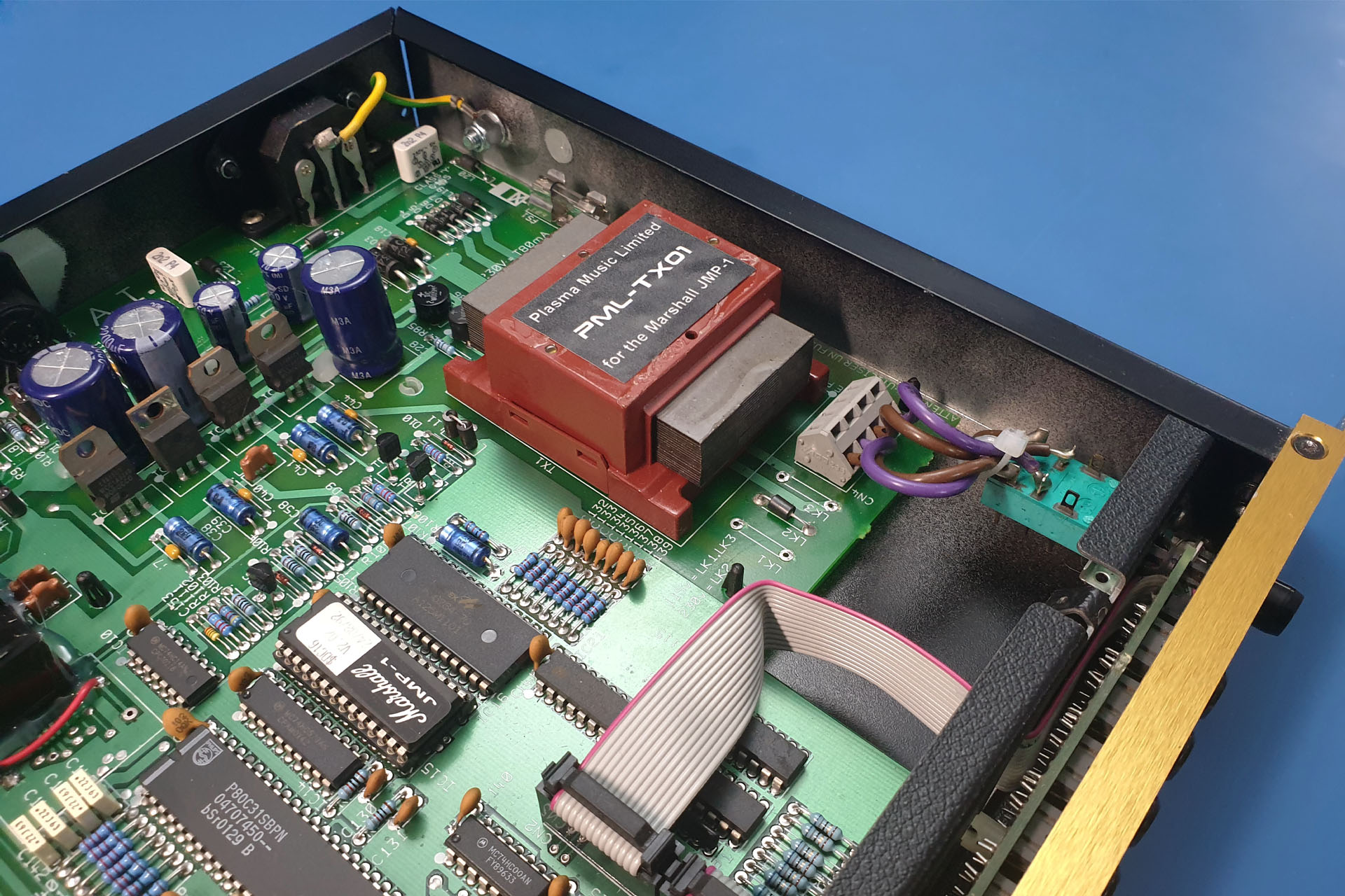
I regularly receive two questions from those interested in my PML-TX01. Both are about the Marshall JMP-1 input voltage selection:
- Is the PML-TX01 replacement transformer for the Marshall JMP-1, 230V or 115V?
- Are the voltage selector components diodes, ferrite beads or just fancy wire links?
The answer to the first question is, just like the original TXMA-00014, my PML-TX01 has two separate primary windings, each rated at 115V. So…
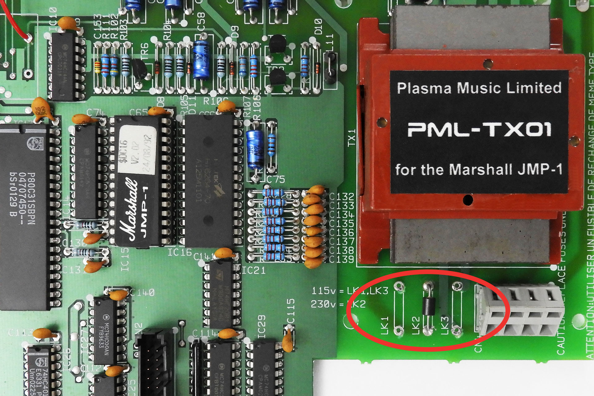
- EUOPEAN / UK VOLTAGE SELECTION. Wired in series, the primary becomes a single 230V winding. To wire in series, connect ONLY LK2.
- USA / CANADA / JAPAN VOLTAGE SELECTION. Wired in parallel, the primary becomes a single 115V winding. To wire in parallel, connect LK1 and LK3.
The Marshall JMP-1 input voltage selection is quite easy to change. The JMP-1 can make it look complicated, especially with the use of those eighties style wire links but the original links were JUST WIRE LINKS and nothing else, so you can use wire.
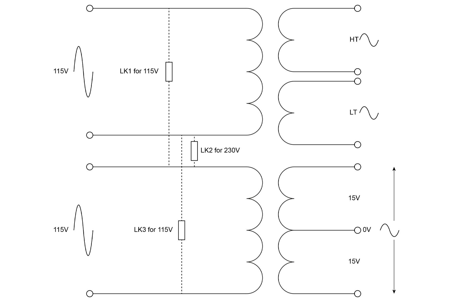
IMPORTANT
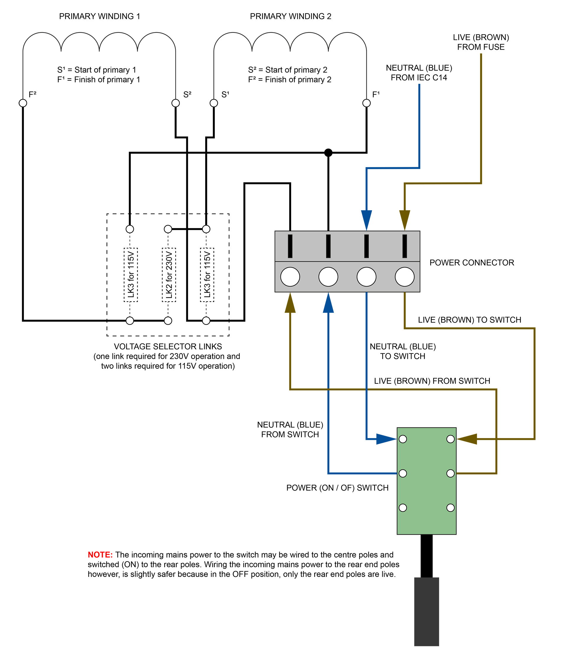
The above is a simple schematic REPRESENTATION of how the links are connected to configure the primaries for either 230V or 115V operation. The physical configuration of the voltage selector links however, is a bit unconventional and suggests that the transformer's primary windings are mirrored with START and FINISH for each winding not being where one might expect! The STARTs, for example could be the the two middle pins and the FINISHes, the two outside pins. Normally, transformer windings would be laid out START - FINISH, START - FINISH. I thought it might therefore be helpful to provide an illustration of the actual (physical) layout of the power input in the Marshall JMP-1 (below).
SIDE NOTE
One might ask why the two individual primary windings are put in parallel for 115V. Why not just use one winding?
Well, a system uses a certain amount of power. Power is the product of voltage and current: P = V x I.
You can probably see now that if you half the voltage, you'll need twice the current to deliver the same amount of power. Placing the two primaries in parallel does just that, it doubles the current going into the system. 🙂
Check out my PML-TX01 low heat and low noise replacement transformer for the Marshall JMP-1 here.