

I'm sorry to say this but I'm not exactly a big fan of modern guitar amps! 🙁 So sorry but I think there's far too much stuff going on for something that should in essence, be quite simple with the important stuff being well... seemingly, not so important! The fact that I had to do this EVH 5153 Mk3 screen grid circuit rebuild kinda says it all.
This amp came to me because it was blowing fuses. The power valves were fried but it didn't look like 'normal' wear was responsible so I decided to open up the amp.
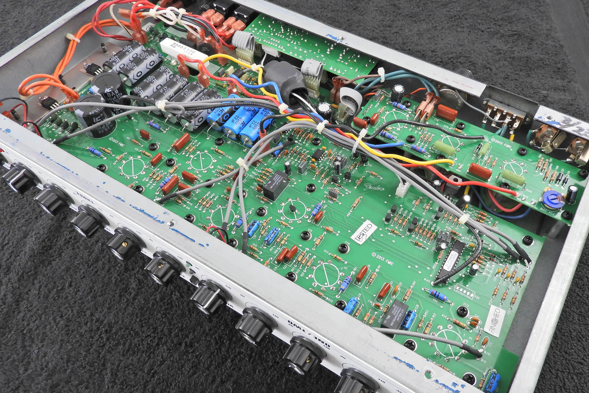
Unfortunately, I didn't take any pictures of this prior to changing components. The image below however, will give you an idea of where the power amp circuit board is (top right). On the other side of this small PCB is a pair of 6L6 valves.
The schematic marks resistors R139, R140 and R157 as 'fp' meaning 'flame proof' which is rather ironic as they were burnt out!
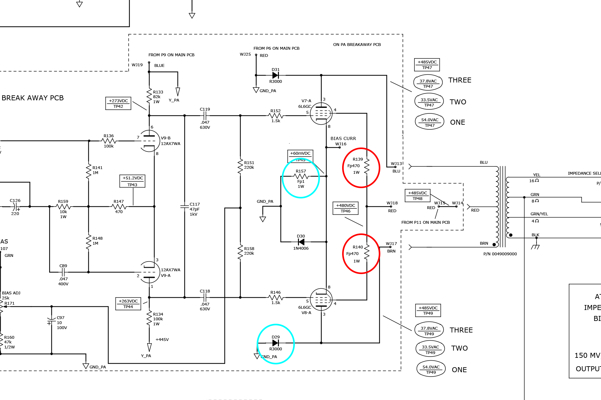
The reason that R139 and R140 failed so dramatically is because of a valve going short-circuit. As this condition occurs, more current is pulled from the screen grid supply. This has the effect of heating up the screen grid resistors, eventually exceeding their power rating and so they blow. It's actually a safety feature to protect more expensive parts of the amp like the output transformer.
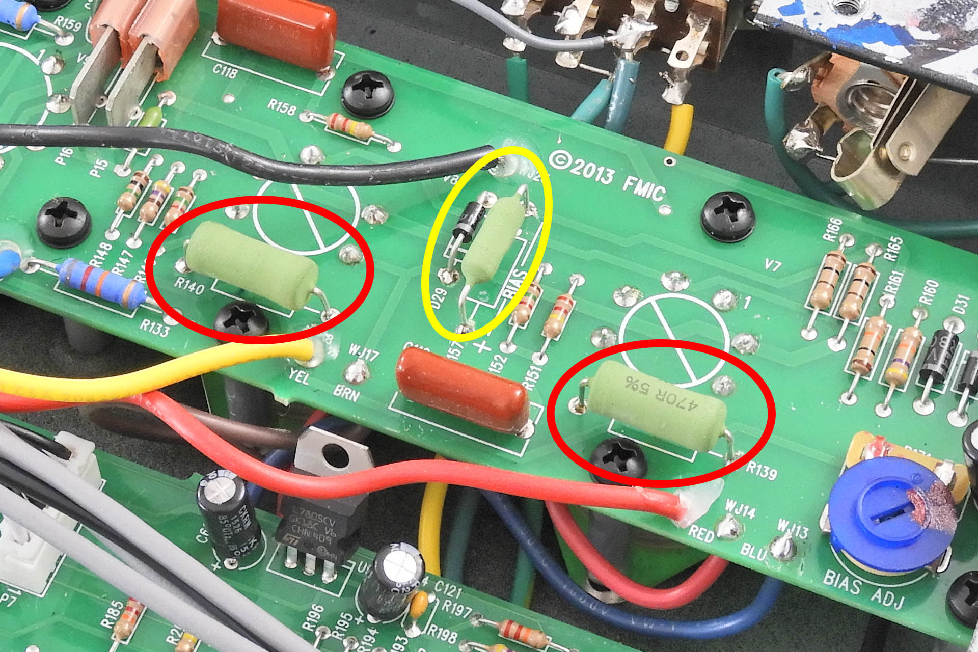
There's a temptation to uprate the resistors to say 2W or even 5W but this isn't a good idea. If the same thing happens again, there's a chance of doing some serious damage. What I did do, was stand the replacements further off the PCB.
R157 is interesting. In many amps, this resistor doesn't exist and the connection is a short. In this amp, R157 looks like it's also there to protect the amp. Similar to a fuse, a 1Ω resistor in this position (between the valve cathodes and ground), helps protect the output stage of the amp, in the event of a valve failure, just like the screen grid resistors. The current flowing through the resistor is less than 50mA and substituting the original component with one of a higher power rating would negate this cool little safety feature. Hence, I decided to drop in a similar 1Ω / 1W device.
The schematic doesn't specify the tolerance of R157 but here's why I chose a high tolerance substitute:
A high tolerance 1Ω resistor (say 1%) in place of R157, also makes bias current measurements easier. Whilst not mentioned on the technical literature, you can clearly see that 'BIAS' is actually written on the PCB next to R157. By measuring the voltage drop across the resistor and then using Ohm's law (V = I x R), it's easy to suss out the bias current. Since R = 1, the current will be the voltage that's read across R157 because I = V / R or I = V / 1).
D29 was also fried. This diode is a plate diode for one of the valves. It may have burnt out because R157 which sits right next to it, overheated or because V8 started pulling more current due to the failing screen grid resistors. Now that the screen grid resistors have been changed however, I think this'll be okay with a standard 1N4006 direct replacement.
If you have one of these amps and are considering a similar EVH 5153 Mk3 screen grid circuit rebuild, please take all precautions. Valves amps bite!
It's difficult to buy a newer amp that doesn't have a printed circuit board (PCB) but I feel that designers need to take care.
While currents are low, valve amps have hundreds of volts all over the place and to route these voltages on PCB tracking worries me a little, especially when the layout is pushed for space. High-voltage carrying tracks often end up being very close to other tracks which in my humble opinion, isn't good.
If we take a closer look at this 5153 Mk III for example, carrying several hundred volts, the track on the positive side of D29 (that's going to the plate of V8) really doesn't seem very substantial and on top of that, it seems a little too close for comfort, to the ground side of R157. 🙁
Sorry for the rant!