Several weeks ago, while in the middle of a request for technical literature and ordering some parts, the kind people at BlackStar suggested that Plasma Music Limited apply to be a BlackStar authorised service centre.
I've been working on amps since 1985 and got into BlackStar as soon as the amps hit the scene. Decades later and it seems that I've been spotted... which is lovely, incidentally.
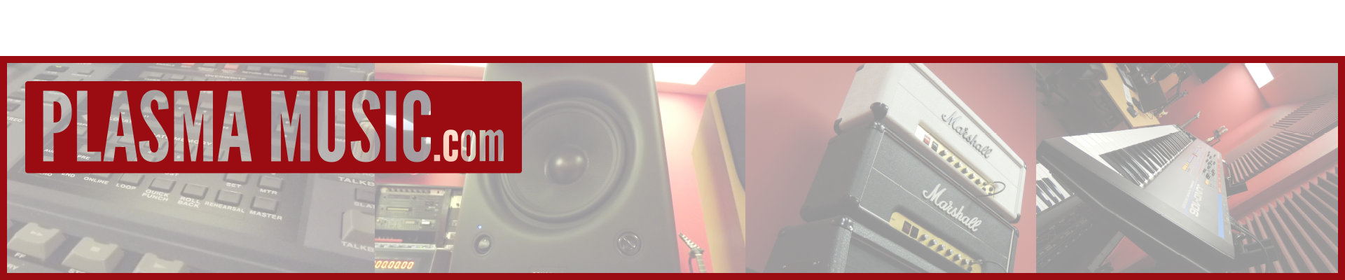
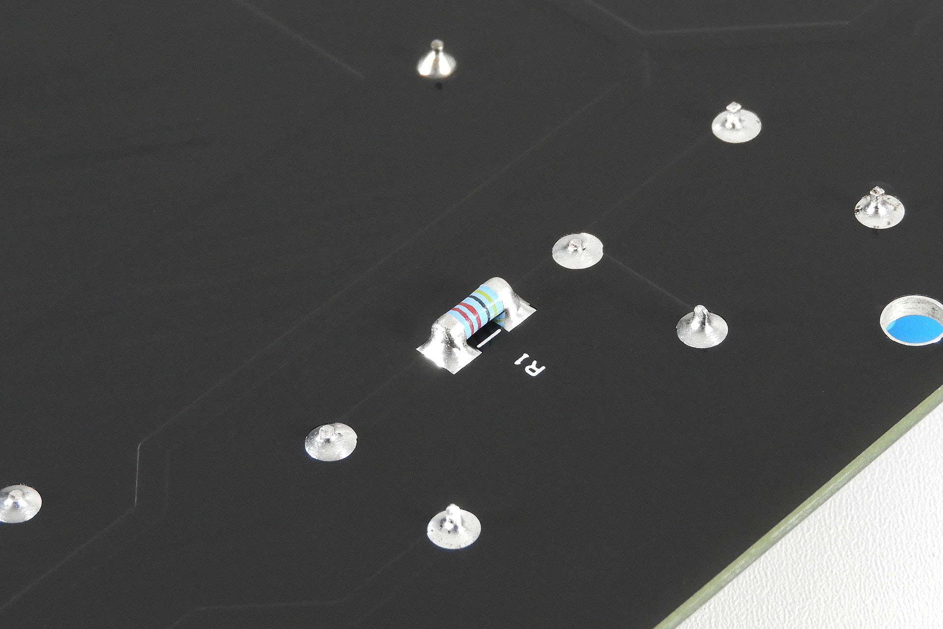
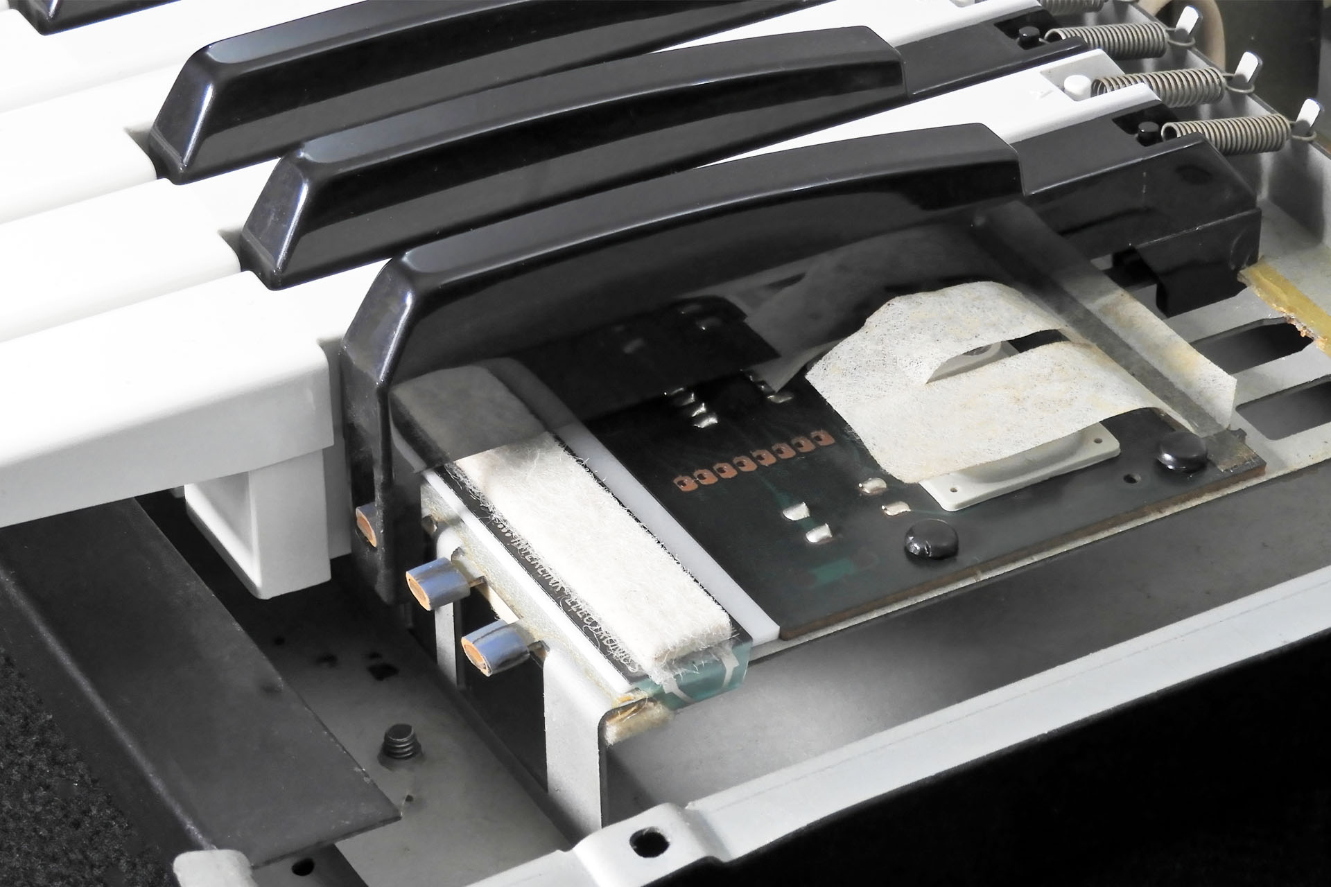
Unbelievably, this brand new force sensitive resistor that was bought direct from the manufacturer, was found to have a damaged track.
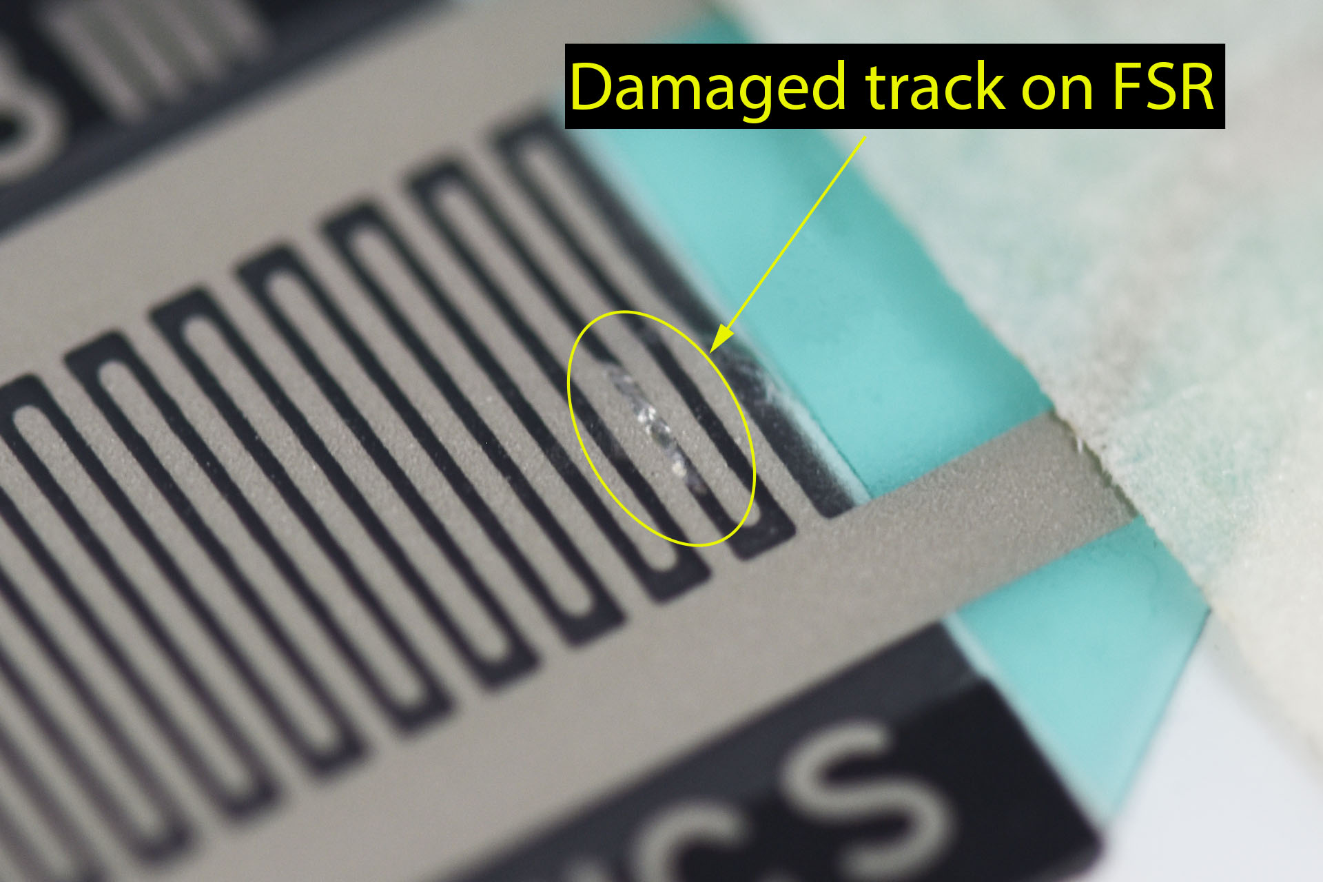
I love designing and making stuff and over the past few years I've been extremely lucky to earn the trust of many customers all over the world. Testing products before they're sent out is a major part of the supply process. To reduce the possibility of sending one of my products halfway around the world, only for it to be faulty, is why quality control is important to me. For some products, I've had to spend as much time designing a test rig as I did designing the product. Other products are tested in a test version of the instrument that they're going into. My Advanced Memory Expansion Pack (AMEP) for the Simmons SDS7 is an example of that. Although I was delighted when I finally put my test SDS7 back together (read all about that here), it remains in my lab so that I can make sure that every AMEP is good before it goes out.
Having said that, my dear friend Guy Wilkinson developed a rig to speed-test and program AMEP. Sorry Guy but I still need to get that all set up. 🫤
Guy Wilkinson built this AMEP tester for me. It can deep test an AMEP in seconds and can also save / write data.
I make several replacement power supplies, all of which use AC / DC converters in a are of modular design. A power supply is the heart of any system. It also handles a domestic supply voltage of anything between 100V and 240V a.c. That means that apart from ensuring that the customer's gear is safe, I also have to ensure that the customer is safe. Yes, I have public liability insurance but that's not the point. Why would anyone design and build peripherals to help extend the life of vintage equipment when those peripherals were unsafe and unreliable? Kind of defeats the object, right?
I was inspired to write this post because today something went wrong while I was in the middle of making three force sensitive resistor (FSR) based replacement aftertouch systems. The second system, an AT-JX-8p (for guess which synthesiser), was kind of acting a bit weird. During testing, pressing one of the sensors near the terminal end, intermittently produced a short circuit. Sometimes it was open circuit. Sometimes it seemed to work fine. On closer inspection, I discovered a small defect in the FSR itself. This was upsetting, not just because I had to make another sensor assembly but because the FSRs I use are one component that I buy directly from the manufacturer. This is a classic example of just why quality control is important and why I don't take anything for granted.
While quality control is important, I'd be wasting my time if I didn't use high quality components and tools. Many won't bother but I wouldn't love what I do if I didn't take pride in it.
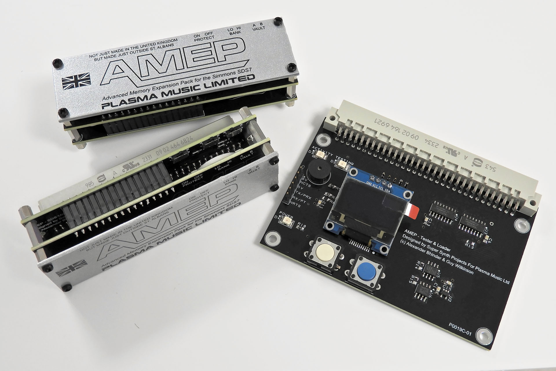
Connectors are often compromised for example because whilst the housings, headers and the terminals may be relatively cheap, the proper manufacturers' crimping tools are not. To ensure a 'secure connection', I have many crimp tools for properly securing Molex, JST and other terminals. These guys cost between 500 GBP and 800 GBP each!
Ensuring quality from the start means using quality components and tools and sometimes that means considerable investment.
Of course, it's practically impossible to test systems 100% but I do what I can. With decades of experience in design and manufacturing, I'm very aware of the things to look out for.
As hinted already, customer safety is paramount. Not only are my products designed with safety in mind, they're tested with safety in mind too.
All my power supplies are fitted with bleed resistors. These devices are connected across live and neutral on the power input and drain any residual voltage left in the filter capacitors that are situated before the AC / DC converters. This means that accidentally touching the IEC socket terminals will NOT kill you! Also, since this component has mains voltage on both of it's terminals, it's mounted underneath the PCB, thus reducing exposed mains on the top of the PCB.
Ensuring that customer equipment won't be damaged as a result of using one of my products, is also very important so following a visual inspection and preliminary testing, everything is soak-tested prior to shipping.
Maintaining a certain degree of quality sometimes requires us to look more holistically at things. "Okay, so here's a really cool piece of gear, now what?"
Fortunately for my customers, I'm as fussy with my installation manuals as I am with the equipment that I make. Sometimes, the installation manuals take longer to compile than the product that they're meant for. Whilst I advocate that those undertaking installing my products have a good level of technical competence, that's of course, something I'm unable to guarantee. My instructions are therefore written with no assumptions. Yes, they may on occasion come across as somewhat patronising but I'm not going to apologise about that.
Taking photographs and knocking up diagrams is particularly time consuming. I don't have a photography studio so many photographs are taken in situ.
Of course, working by myself presents the issue that I'm forced to test and QA my own work. That's not at all ideal. Being a bit old fashioned, in the studio for example, I'm dead against mastering my own material. Tracks always get sent out to someone who can be objective.
In a production environment, QA is performed by a department that is quite separate to manufacturering. I'm unable to do that which means that I need to be extra vigilant. It's very frustrating.
Some Lovely Feedback... I recently sent an AT-JX-10 replacement aftertouch sensor kit to a customer in Florida. I was then contacted by Kris Rogers, ofProAudio ElectronicsOpens in a new windowin Tampa, requesting installations instructions. I was initially a bit confused as installation instructions are available after purchase and are also emailed to the customer on confirmation of shipping. Anyway, after getting a few details, I obliged Kris who was fitting my aftertouch system on behalf of the customer who purchased it. Well, this afternoon, I received the most lovely email from him:
"Alex,
I just wanted to complement you on the layout of these instructions. They're very well written, you did a fantastic job on this. I have done a few mod kit installations across many different types of keyboards and yours is by far the best I've seen.
Hats off, very well done.
Thank you for your help,
Kris Rogers"
The written word that accompanies my products, reflects my personality, my character, my passion and I hope, professionalism. I believe it important that people know just what I'm about and that the item they've purchased was made and is supported by someone who cares. It's very reassuring that people like Kris notice these things.
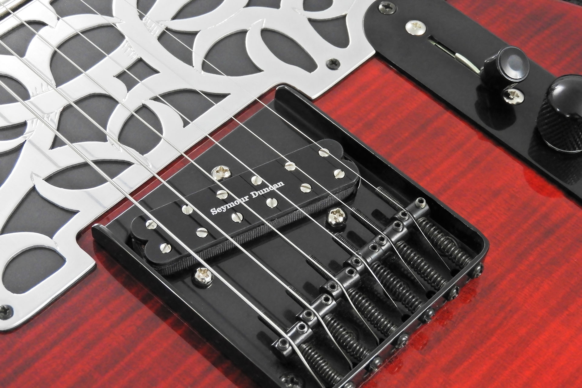
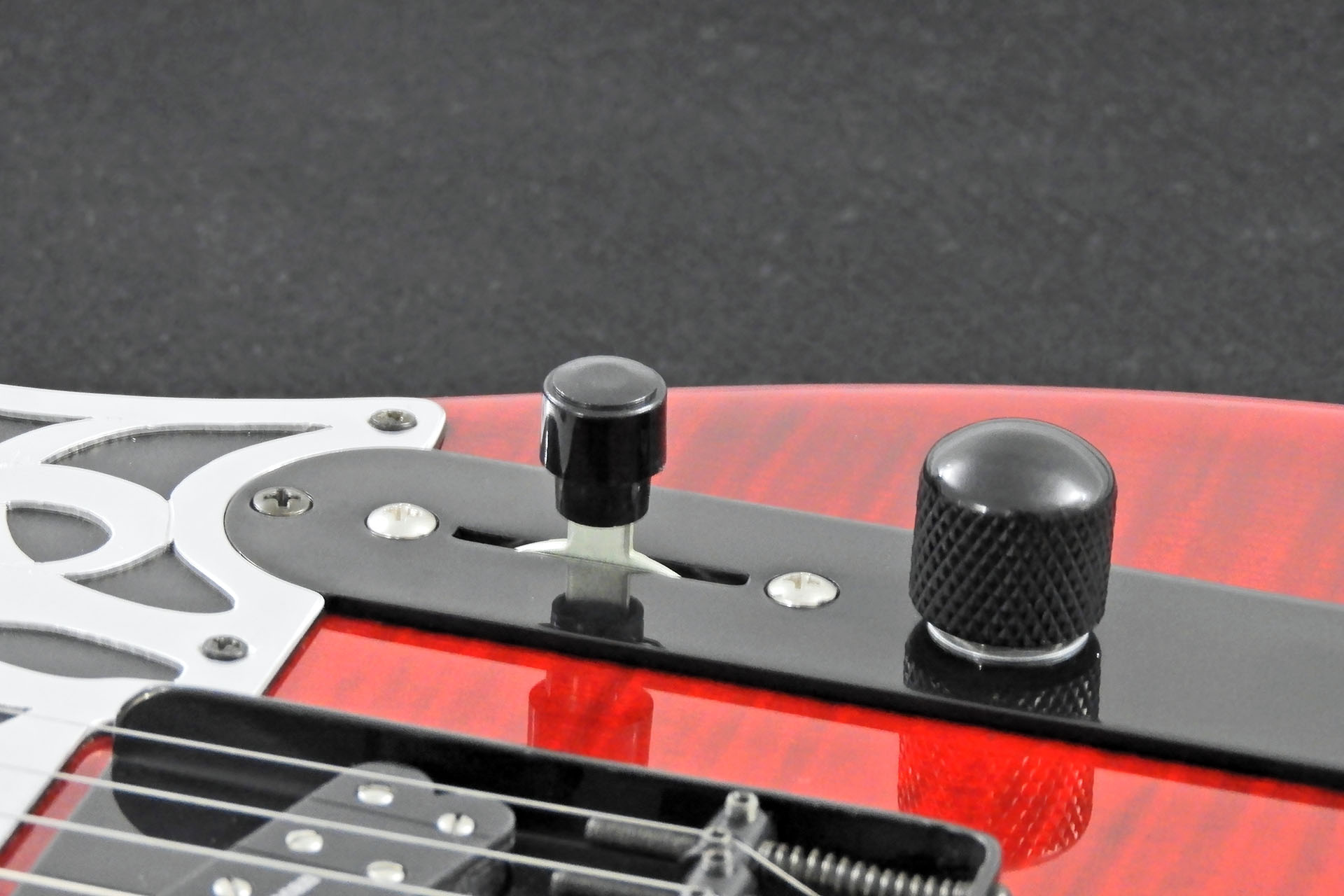
Here's my new Seymour Duncan Jeff Beck Jr Bridge fitted into my homemade Telecaster. And YES, that's a 2-layer steel-top scratch-plate.
I'm no expert, just some guy who likes a certain tone (or two). This is the first time I've used a single-coil format humbucker and just decided to publish my opinion so here's my Seymour Duncan JB Jr. for Tele review.
Round about 2014, I crazily decided to build myself a Telecaster! It was even a strange decision back then as I'm very much a humbucker kind of guy but for those classic jangly Gothic riffs and the cool look, well I figured I'd go where no Alexander Bhinder has gone before.
I've been fortunate to work on a variety of customers' guitars and fell in love with Lola pick-ups a long time ago. Recommending them and subsequently fitting them, I chose Lola for my Tele build.
Well, the neck pick-up turned out exactly how I expected but I was never happy with the bridge pick-up. For my ears and for my music, the Lola was way too light and sparkly. It was such a shame as I grew quite accustomed to the guitar itself.
Twelve years later, I thought I'd revisit my ol' Tele build. Wow, this guitar feels great! I can't believe it stays in tune like it does. Anyway, being a big Seymour Duncan user, I was quite aware of the company's 'slim' humbuckers which were developed to drop into single-coil cut-outs. There was one barrier that I had to overcome, though...
I'm ever so slightly old fashioned. The bigger the CC, the more powerful the car, right? Similarly, I've always been doubtful how you can get that full-on humbucker raunch in well, something half the size. After twelve years of being a little disappointed with my Tele build, I thought "what the hell. Just give 'em a go."
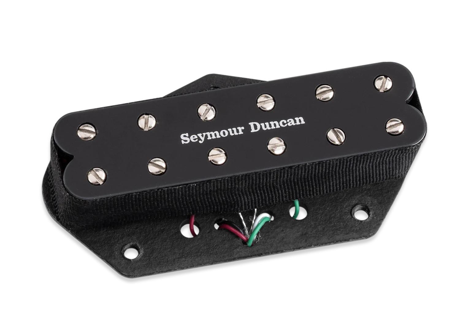
A quick look on line and the Seymour Duncan Jeff Beck Junior for Tele bridge popped up. This was particularly encouraging as several of my guitars have JBs in them. So I bit the bullet and a week later (of course it was out of stock everywhere) the pick-up arrived.
!!! Image taken from Seymour Duncan website (I hope Seymour won't mind too much).
Actually, that was quite good as I had a little time to research things like pots. Do I stick with the 250kΩ volume and tone controls that are in the guitar or do I swap them out for 500kΩ potentiometers? And then there's the 470kΩ resistor mod which some people recommend. Please bear in mind that I'm keeping the Lola pick-up in the neck position so I need controls that'll work with both devices.
Seymour Duncan recommend 250kΩ pots so I figured that would be a good place to start.
Reluctantly, I pulled the Lolo bridge pick-up. I have to admit that the experience was a bit emotional. On this guitar, I wasn't interested in configuring the coil-tap feature of 4-conductor pick-ups so dropping in the new Seymour Duncan JB Jr. was pretty straight-forward. The only disappointment was that the shape of the new pick-up resulting from the dual magnet configuration, didn't sit as neatly as a normal single-coil. The only workaround would have been to put a cover over the pick-up but of course, you don't do that with Seymour Duncans, do you! 🤣🤣🤣
Okay, let's put everything back together and see what the Seymour Duncan JB Jr Tele sounds like...
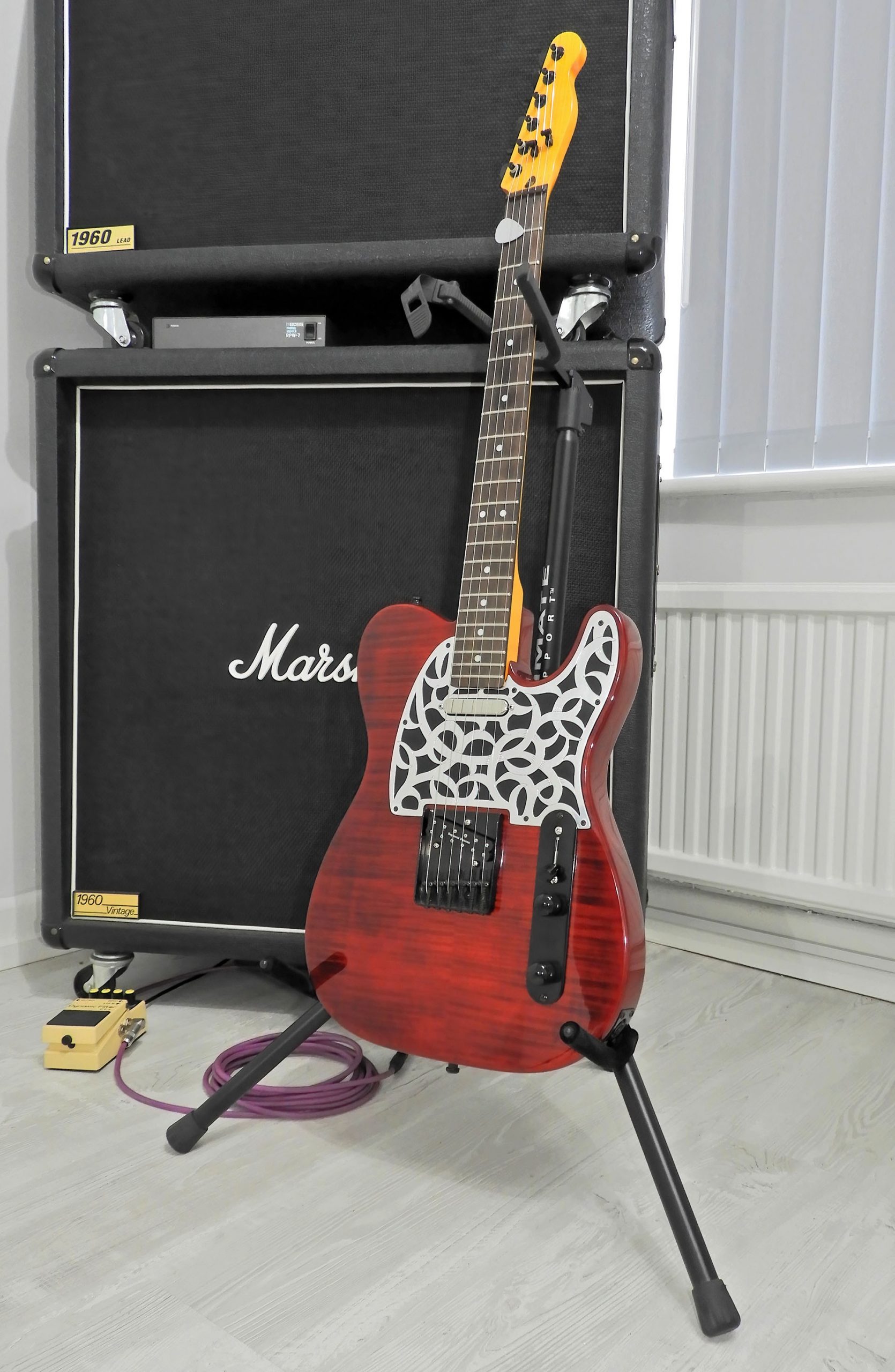
Here's my Telecaster build from 2014 now loaded with a Seymour Duncan JB Jr Bridge. Still got the Lola in the neck.
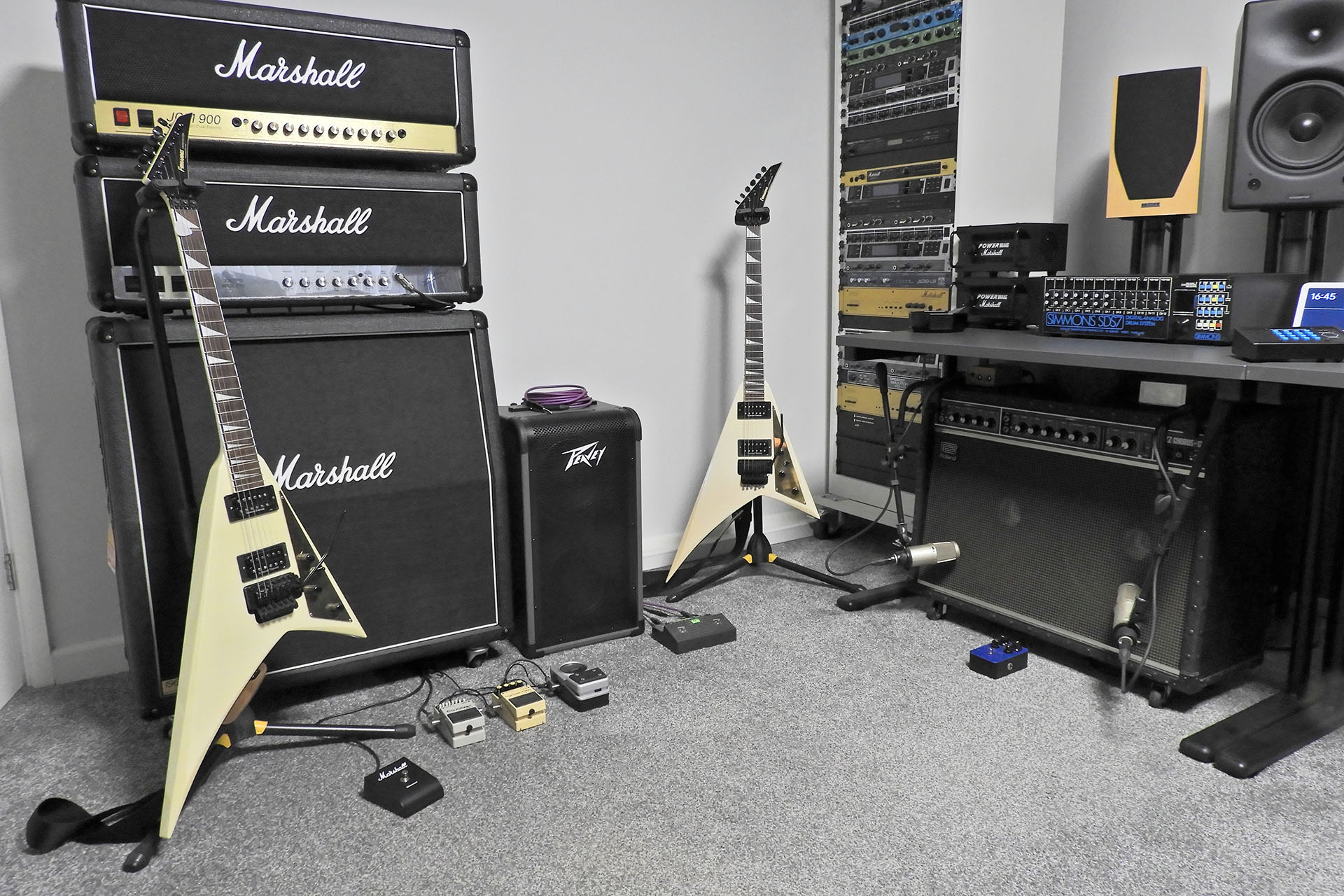
Before you read anymore, please be warned... If you want a Seymour Duncan JB Jr. for Tele review that includes sound bites, then look no further than the Internet! There are lots of much better guitarists out there than me, demonstrating this pick-up so I'm not going to do that, LOL. Another reason I'm reluctant to provide sound samples, is because I'm a believer that while the transducer (pick-up) conveys the feel, most of the sound comes from the amp. Yeah, I know, some of you will be getting angry tight now and disagreeing with me. Well, that's your prerogative but please note (for a start) that I said "most of the sound". I've worked with a lot of artists. some of whom are quite well known and my perspective is based on several decades of observation. Anyway, let's not get distracted. The reason I'm actually making this point, is that although my Tele build was supposed to be for clean guitar sounds, the new pick-up suggests that it might now go beyond that and into something a little more overdriven. Indeed, this Seymour Duncan JB Jr. for Tele review is was based on playing my Tele build into my old (but pristine) 1979 Roland JC-120 and my original (1987) Marshall Silver Jubilee 2555. Why two amps? Well anyone familiar with the JC-120 will undoubtedly be aware that while the clean sound is quite special, the distortion sucks!
As you can probably tell, I kind of like things a little heavier than most might imagine a Telecaster to deliver! And YES (well spotted), the Silver Jubilee isn't silver. Long story but those in the know will understand when I mention serial number 24.
One aspect of single-coil pick-ups I really like is their phase coherency. For what is effectively, an inductive component, phase distortion seems to be minimal... for a simple inductive component, that is. This characteristic of single-coils manifests itself as a very tight and punchy bottom end. What blew my mind when playing the JB Jr. clean into the JC-120 in particular, was that although this pick-up is of course a humbucker, it had an amazing bass response which was strong, deep and tight. Note that I haven't said "big". It's just really neat. This was completely unexpected and a most pleasant surprise.
I'm now going to mention 'response'. "Er... why?" I hear you ask. Good question as response isn't normally a parameter which is talked about when it comes to something like analogue electromagnet transducers used for musical instruments! Let me explain...
Firstly, I'm talking response in this context referring to dynamic range and transient attack. Yes, you'd be forgiven if you think that this is kinda synthesiser talk but please bear with me.
Single-coils into a clean amp always seem to have more dynamic range than their humbucking counterparts. Due to the compressing nature of overdrive and distortion, dynamic range into a dirty amp simply isn't the same, being very much more reduced. So let's go back to the clean amp (my Roland JC-120). To my ears, the Seymour Duncan JB Jr. for Tele seems to have the dynamic range I would normally associate with single-coil pick-ups. This shouldn't be the case because yet again we need to remind ourselves that the Seymour Duncan JB Jr. for Tele is a humbucker. Weird but that's how it is.
The same can also be said for transient attack. As soon as you touch a string, the Seymour Duncan JB Jr. for Tele let's your amp know!
To summarise, the Seymour Duncan JB Jr. for Tele is very responsive with a considerable dynamic range and a fast attack.
Okay, so now let's try this thing into something a little heavier (one of my Marshall Silver Jubilees).
The master volume on all my big Marshalls is set to just above 6. Yes, they all go into power soaks (otherwise I'd be deaf). All my big Marshalls are 100W because I like that sound. I didn't change anything on the amp that's used to having anything from my Gibson Les Paul Custom to my Jackson RR-1 plugged into it.
This pick-up was awesome! With a thick and tight bottom end, the mids were rich and chocolaty while the high-mids provided much articulation and definition. Guys, I didn't expect this... I really didn't. So I have a pick-up that feels like a single-coil into a clean amp but crunches and screams like a humbucker into an overdriven amp.
The spectral spread was classically vintage with no phased type resonances. I call this an 'open sound'. This is one reason why a few of my classic guitars are loaded with the humbucker version of the JB.
To my ears, the lack of over-sizzle told me that the JB Jr. wasn't using ceramic magnets but they were a bit too 'loud' to be anything less than Alnico V. After a little digging, my hunch was proved right and indeed the JB Jr, uses Alnico V magnets.
So, one last test and the only test which uses the Lola neck pick-up and for this I went back to the JC-120.
The combination of the Seymour Duncan JB Jr and the Lola neck wasn't quite what I expected.
I flicked the pick-up selector switch to the mid-position thereby combining both the Seymour Duncan JB Jr. for Tele and the Lola. Wow, that's interesting. The sound was obviously dominated by the higher output Seymour Duncan JB Jr. for Tele. The Lola's influence was quite obvious, though providing an interesting edge but not as much tone shift as one might expect from combining the two pick-ups on a dual single-coil Tele.
To conclude, the Seymour Duncan JB Jr. Tele is NOT a cooker! This is a medium output pick-up. Considering gain / bandwidth product, this pick-up definitely leans towards tone (bandwidth) as opposed to output level (gain) but that's exactly what I wanted. I didn't try this with any heavy metal settings, just classic rock overdrive. Somehow the bottom remained tight and the top smoothed out nicely with notes remained perfectly defined. I'm not sure if 500kΩ pots would have made things sound better but with the 250kΩ volume and tone controls that were already in my Tele, I thought things worked well. I've hinted at this already but I have to say it again... I was completely taken back by this pick-up! Somehow, it maintains aspects associated with single-coils but delivers the crunch when and where you want it. Would I recommend? Oh yeah... most definitely! In fact, I'm thinking of dropping a JB Jr. standard single-coil into my Fender Custom Start.
"Seymour Duncan, I apologise for getting it wrong. The single-coil format humbucker works and I'm so glad I decided to try this pick-up!"
Seymour Duncan's website is packed with really interesting and useful stuff so if you want more information than what's here in my Seymour Duncan JB Jr. for Tele review, please don't hesitate to check this out.
Since being back at work (officially), I’ve had one or two orders come in. Some of these are complete but unfortunately, everything that uses Vigortronix AC/DC converters won’t be going out for another couple of weeks as I’m desperately waiting for an order to come in. The good news however, is that I'm back with a busy May 2026!
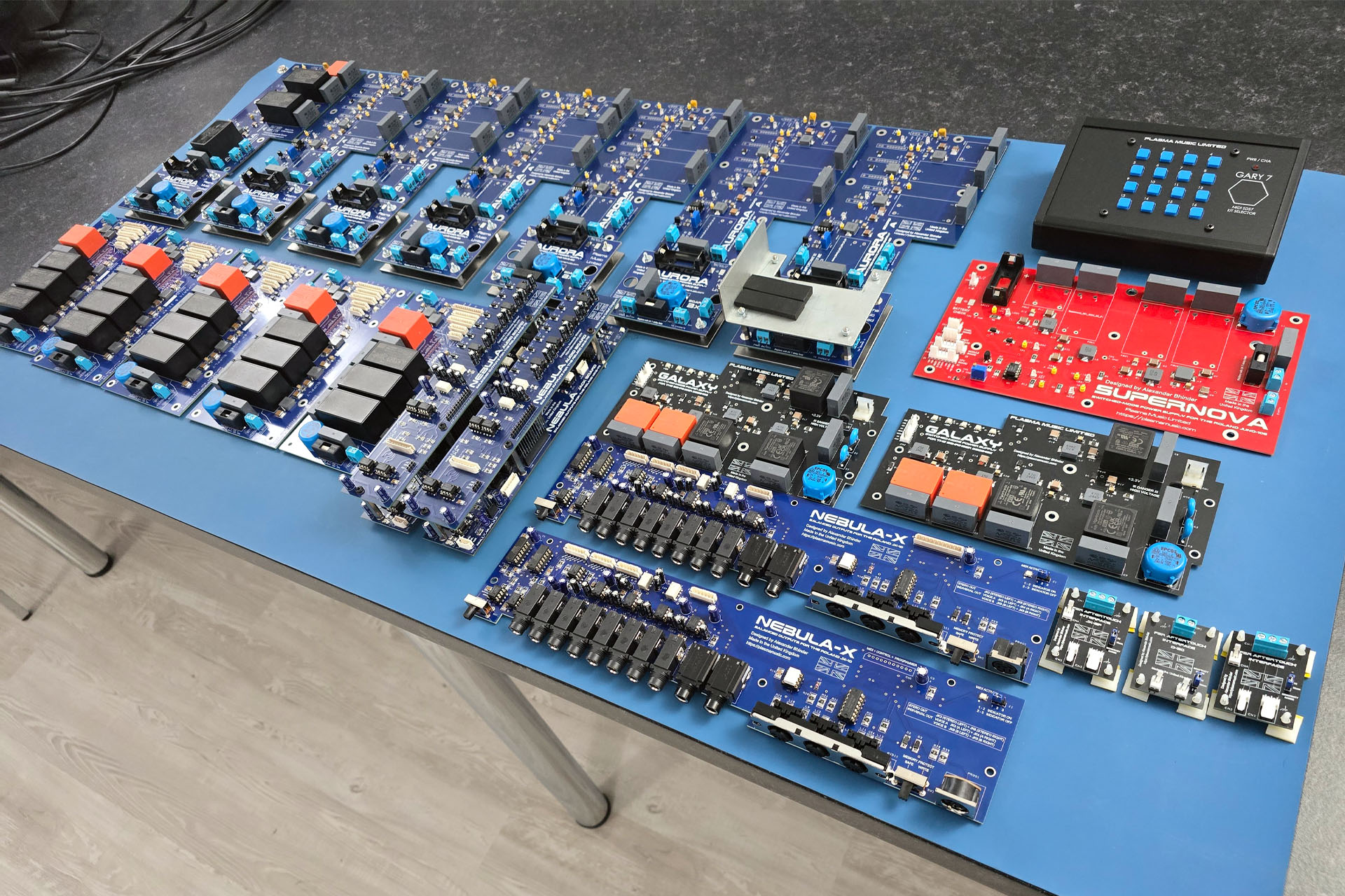
At the back are seven Aurora replacement power supplies for the MKS-80, only one of which is fully built. The red Supernova replacement power supply for the Roland Juno-106 is also waiting converters.
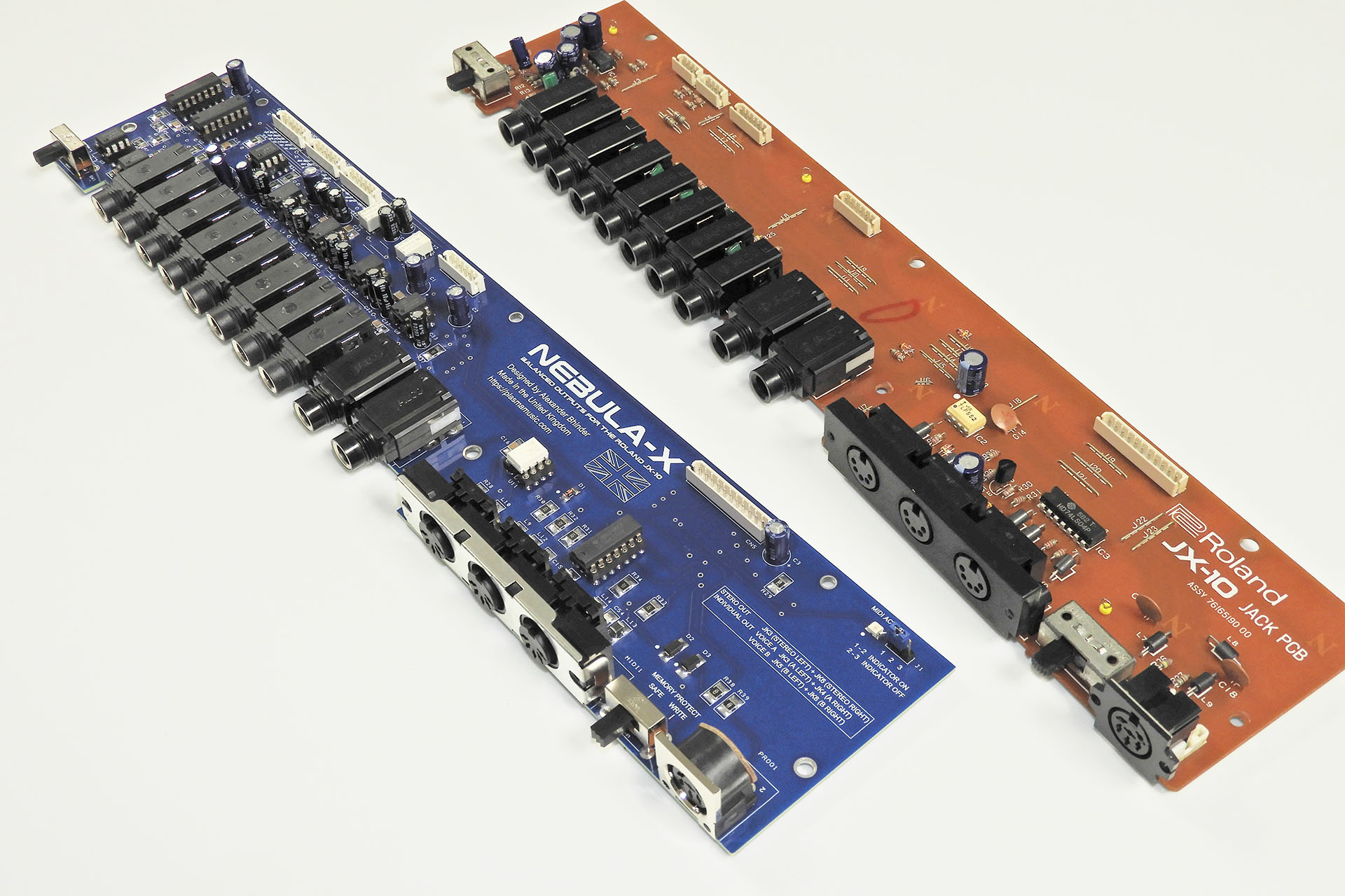
All of the five P0004 replacement power supplies for the JX-10 and MKS-70 (left, front) are now built and have also been tested. These should be shipped in the next few days. The same with the two black Galaxy replacement power supplies for the Behinger DEQ2496.
Also pictured are two Nebula balanced outputs for the Roland MKS-70 and my first two orders for Nebula-X balanced outputs for the Roland JX-10 (front, centre-right), one of which needs a Molex connector which arrived a few minutes ago.
To the right of them are three FSR Aftertouch Interface (FAI) PCBs, one for the Roland D-50, one for the Roland JX-8P, one for the Roland JX-10. I’ll be building the sensors for those over the weekend.
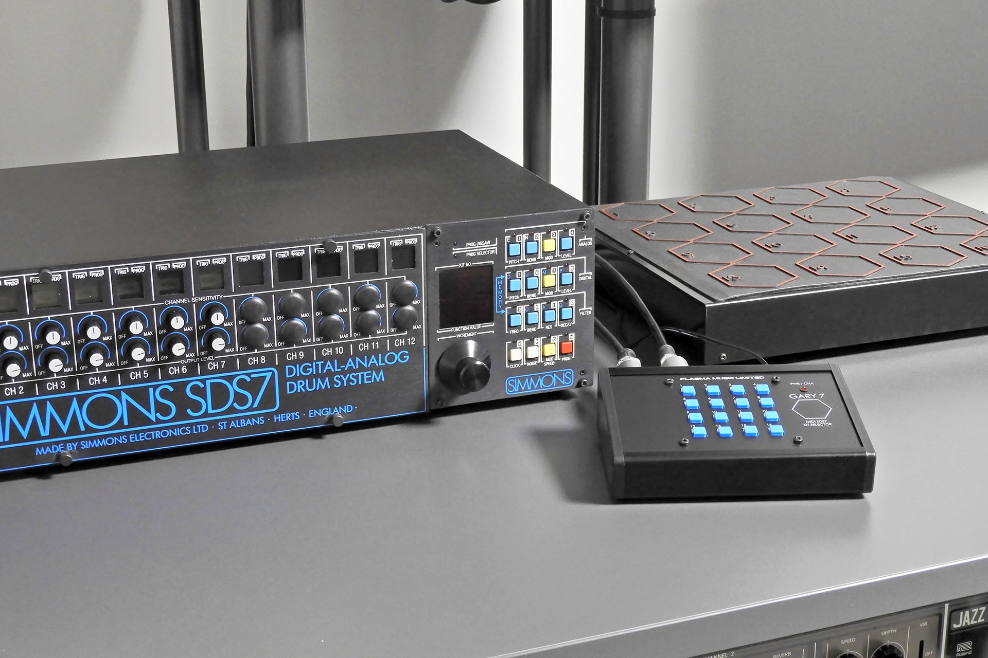
At the back towards the right, is my first Gary 7 sale. Gary 7 is a MIDI patch change to Simmons SDS7 kit change converter which was one of my Christmas 2025 projects, the other being Nebula-X.
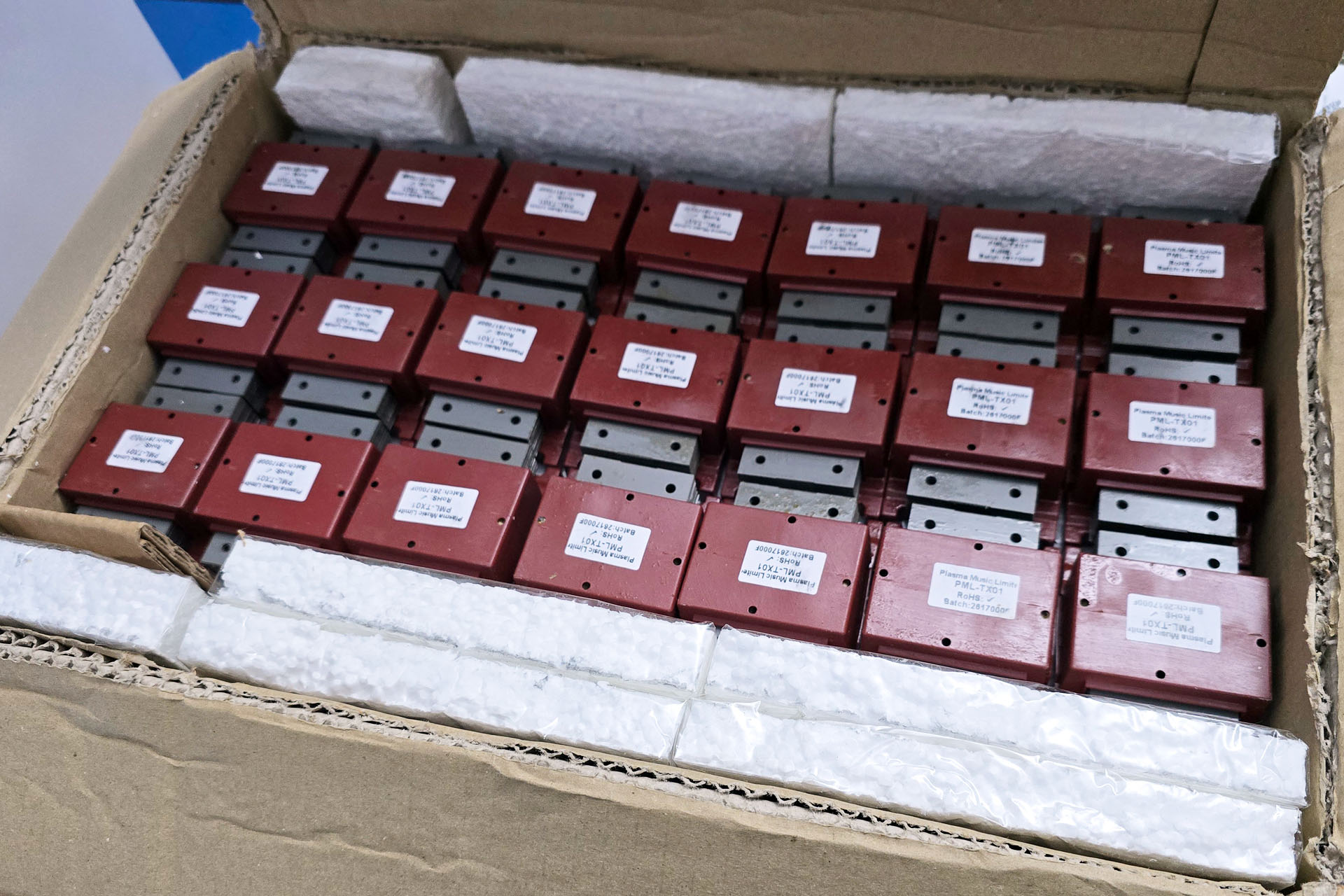
The top tier of the box of PML-TX01s that I just received. Should keep my JMP-1 customers happy for a few months.
Pictured above is my 2026 batch of PML-TX01 replacement transformers for the Marshall JMP-1. Some will recall the issues I had with last year's shipment. ParcelForce just couldn't get it right and the delivery was months late.
This time around, the transformers arrived much quicker as the factory kindly decided to use a different courier, one which doesn't use ParcelForce on the home (UK) leg.
As if that's not enough... While building all that stuff, I’ve also managed to catch up with ALL the repairs that came in prior to my operation and have been accepting repairs for the past few weeks.
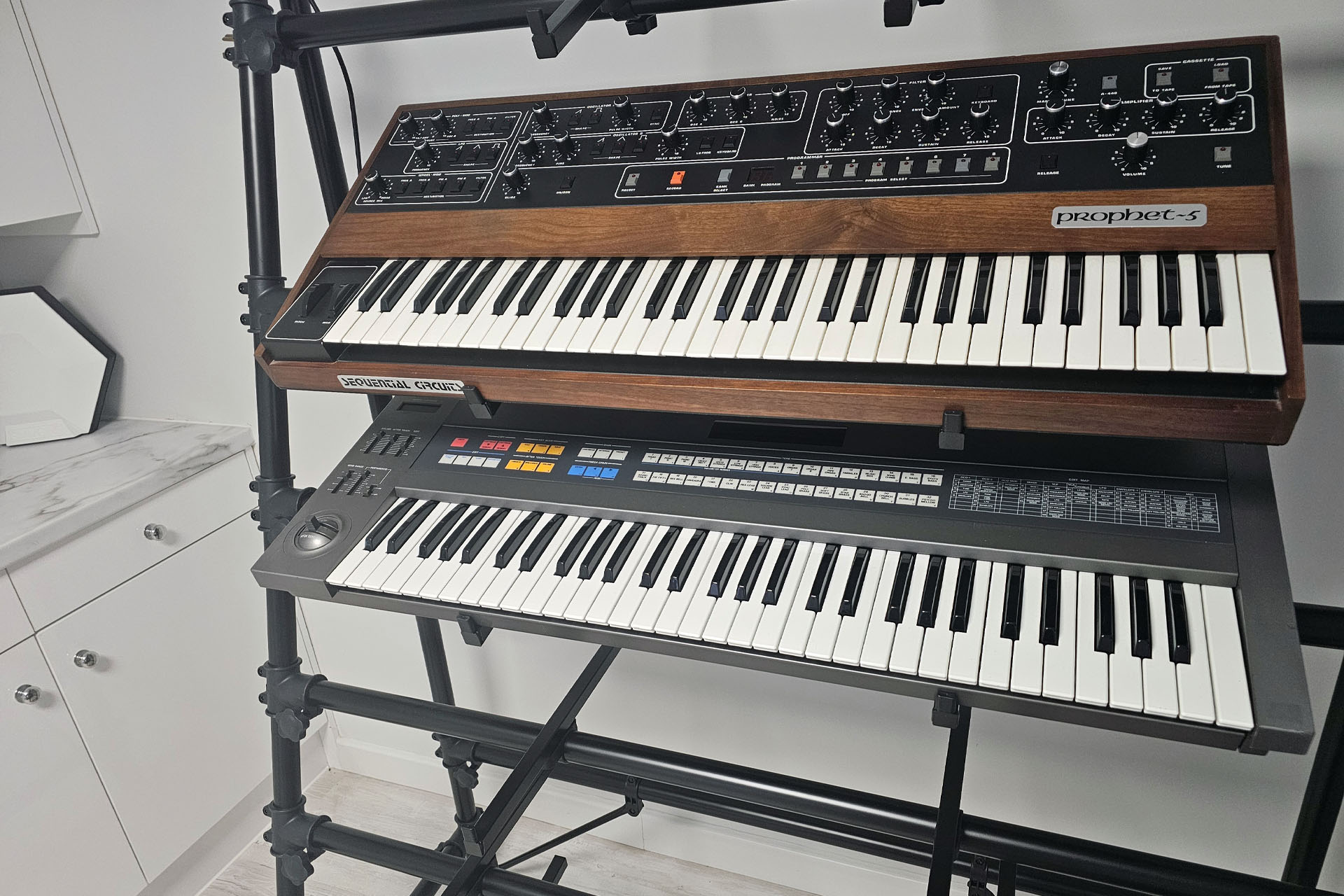
The last two keyboards that came in prior to my op including an immaculate Sequential Circuits Prophet 5 from 1981. Both of these instruments were a bit challenging in their own way but I'm glad to report that they're both now working just fine.
❤️ On a personal note... I'm back with a busy May 2026 and it feels great getting stuck back into things. People have been just so fantastic and THANK YOU for all the lovely emails and messages. I'm feeling fine although I still have a couple of appointments coming up, just to make sure all's well. I've been told that full recovery might be between eighteen and twenty-four months but seriously, I'm very almost back to how I felt before the op.
I'm sorry about the supply problems and don't blame people for kind of thinking "if it's not one thing, it's another". All I can promise those who are waiting for my power supplies that use Vigortronix converters is that as soon as they turn up, I'll be working full on to get your orders out. As can be seen in the title image, all power supplies have been built. I just need those frigin' converters, 😡
One afternoon in late September 2025, a customer turned up to collect his Marshall JCM-800 combo that I’d serviced. My customers mean everything to me and it’s not unusual for those who turn up at my door, to stay a while. 😊 Anyway, Iain and I really hit it off and after mentioning his software work, I told him about my Gary 7 MIDI kit selector for the Simmons SDS7 idea.
Gary 7 was going to be another one of my software-based ideas which would probably never see light of day but then Iain offered to pop over one afternoon to help get me started with coding for the Raspberry Pi. First, he gave me a short list of various bits ‘n’ pieces I should buy in advance of his visit.
Well, Iain stuck to his promise and sometime in November 2025, he came round to explain how Raspberry Pi stuff worked. We had a fantastic afternoon and I learnt so much. THANKS Iain! 😎
Unfortunately, it was also roundabout this time that my doctor told me that a recent routine blood test had come back with a high PSA level. As it turned out, I was eventually diagnosed with prostate cancer. As you can imagine, the news was quite devastating. On the other hand, life goes on and the only way I could focus on the future was by being with my family and working on stuff that I love… like Gary7.
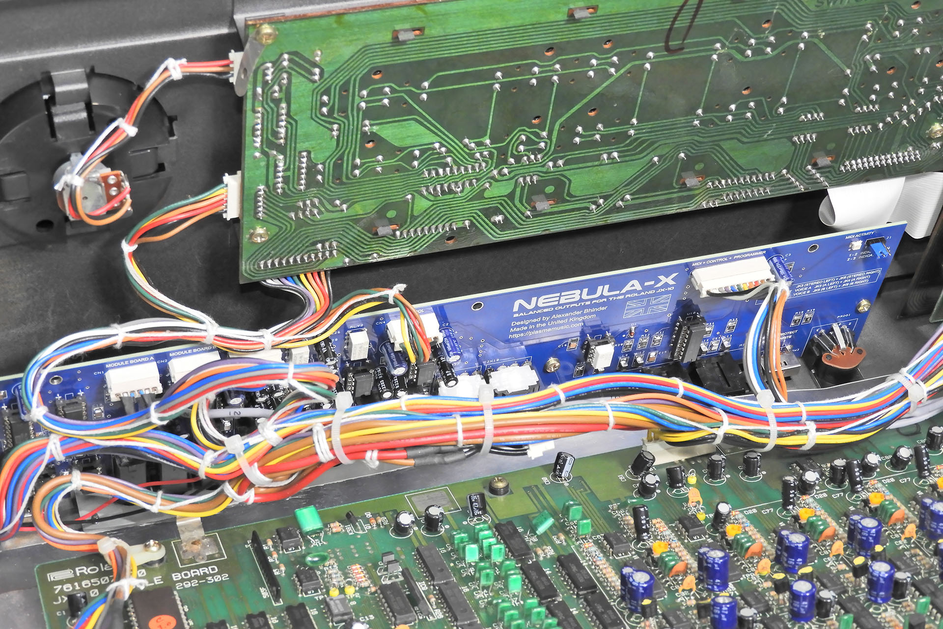
I also had another project that would help keep my mind off things. Nebula-X balanced outputs for the Roland JX-10 had been on my shelf for a couple of years. My third and last revision PCBs had been delivered and I was very keen to get this done too. Hence, my Nebula-X project took priority over Gary 7.
Nebula-X balanced outputs for the Roland JX-10 was another project that kept me distracted from things.
Iain introduced me to the whole Raspberry Pi thing and showed me stuff which, if I had to suss out on my own, would have taken me weeks if not months. More than that, his patience and general way was particularly inspiring. Iain’s a Java programmer specifically but showed me some Python code which kind of pointed towards what I wanted Gary 7 to do. Yes, I know that the firmware used for MIDI is either written in C or C++ but it wasn’t about the language or code. Iain had a way about him and well, gave me the confidence to make a start. It was a kind of Eureka moment, if you like.
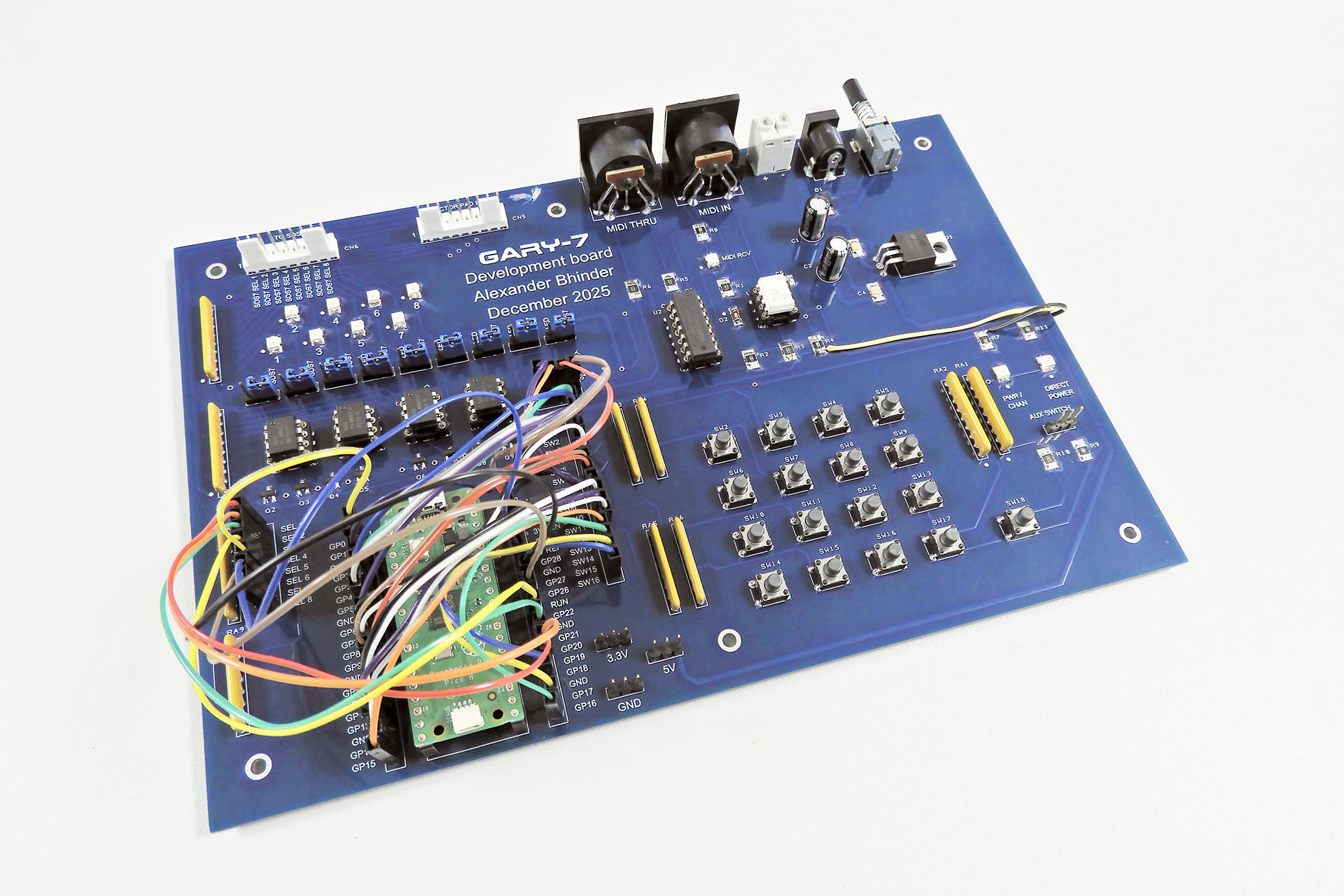
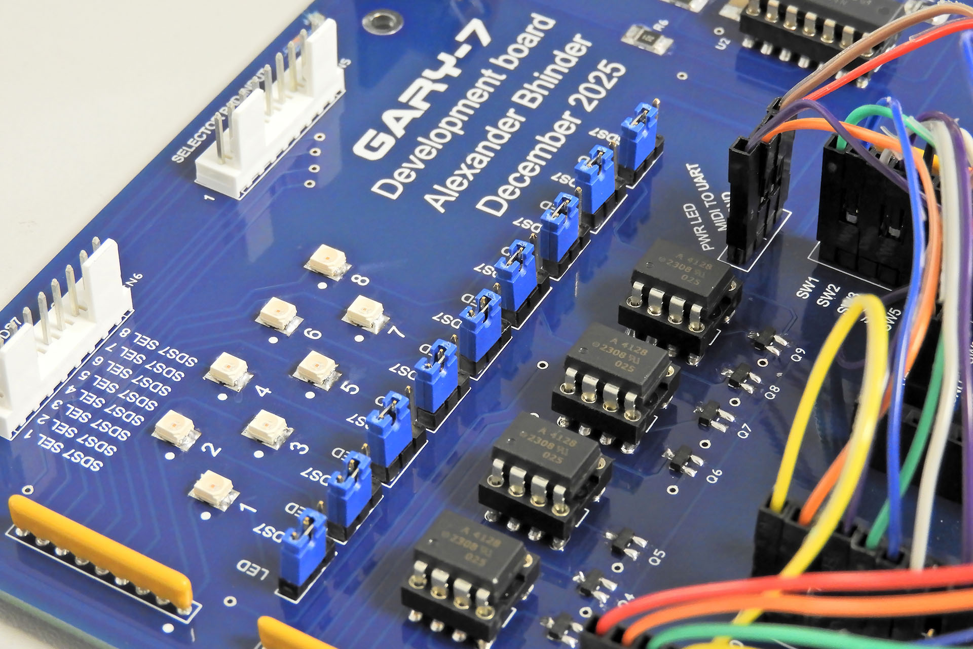
While I toiled with how I was going to approach this whole software thing, I began designing a development board for Gary 7. This was by no means a prototype but simply a board which had a lot of open connections and which would allow me to easily change things if necessary. I believe 'versatility' is the word I'm looking for.
Indeed, although the objectives of this project were quite straight-forward, there was one major aspect of my Gary 7 MIDI kit selector for the Simmons SDS7 in which I had no real experience and that was of course, software.
My Gary 7 development board happened quite quickly. Of course, I didn’t use a full Raspberry Pi but chose the much smaller Raspberry Pi Pico. I was soon talking to Iain and other friends about the best way to proceed.
Of course, most projects require prototyping but Gary 7 was my first project for which I decided to build a specific development board.
On a side note, with a chunky 7805 regulator, Gary 7 can be powered from an external 9V - 12V DC power supply. 😎 I used a 12V PSU just to check that the 7805 could deal with the voltage drop across it while delivering the current that the board required.
I’ve always been quite critical of AI but this project seemed to be an ideal opportunity to ‘have a go’. It was round about this time that another new friend and I decided to meet up.
As soon as Mike Walden announced his newly designed main-board for the Simmons SDS6, I contacted the customer of a unit that had been brought in to me and subsequently bought the first of Mike's boards. That was almost a year ago. Since then Mike and I have hooked up several times on line but just before Christmas 2025 he kindly agreed to come over to my place to chat Simmons SDS6.
I mentioned Gary 7 to him and that I was considering using AI to develop the software. "Give it a go. See what happens" was his response. With a lot of initial help from Iain and a word of reassurance from Mike, I decided to start where everyone starts and that was with a prompt, a detailed and methodical description of my objectives and the means with which I intended to deliver them. That might sound simple but like most things in life, what you get out of AI is only as good as what you put in.
On a sidenote, if you're interested in Mike's replacement main-board for the Simmons SDS6, you can read more here.
My Gary 7 development board, allowed me test the selector input/output matrix by hitting eight LEDs, before hooking things up to an actual SDS7.
December 2025 was a weird time for me and my family. Nebula-X and Gary 7 were much needed distractions and with the latter, I also immersed myself into the whole AI thing. It only took me two prompts to get something working but boy, did I learn a lot.
After getting the MIDI to SDS7 kit selector lines to work, I decided to push things. With sixteen switches to allow manual kit selection of the SDS7, I introduced a way of setting Gary 7’s MIDI channel with those switches, for example. Of course, it would have been kind of frustrating if Gary 7 didn’t remember the MIDI channel. Hence, the set MIDI channel had to be written to the Pi Pico’s memory. Then I came up with the idea of getting Gary 7 to remember the last kit selection prior to power-down. I referred to this as 'the last command'.
Early tests revealed unreliable memory retention so this had to be addressed and so the memory architecture and management of the Pi Pico were examples of what I learnt from the AI that I was using.
All versions of Gary 7 up to 1.6 were developed with the aid of AI so that was six prompts. I specified that all variables should be listed at the top of the code so tweaking the next three versions of the software was easy and something I could do myself.
By version 1.9, Gary 7 MIDI kit selector for the SDS7 was rocking!
With my cancer prognosis constantly in the back of my mind, getting Gary 7 MIDI kit selector for the Simmons SDS7 working was just so exciting, I just had to record it all. The two videos below show my bench testing.
Before I continue, let's quickly consider the whole kit selector thing of the Simmons SDS7 and the hardware I chose to do this...
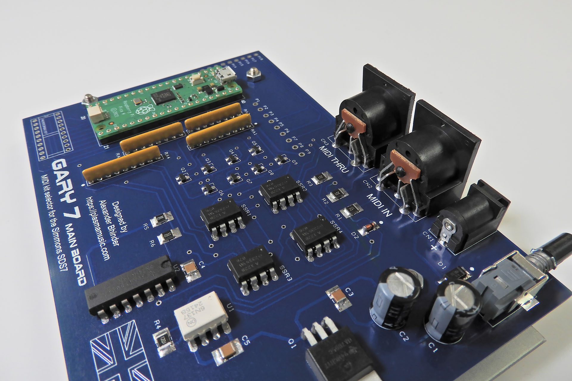
The mechanism behind the kit selector of the SDS7 is simple but ingenious. Four signals from the SDS7 are switched to four outputs in a rather clever combination so as to allow for sixteen options. Gary 7 uses optical relays, emulating the zones or ‘pads’ on the Simmons selector pad, thus switching the four signals in the combinations required, to the four outputs.
Now then, questions could be asked like…
“Why have the expense of the opto-isolated relays when I could have just got the Raspberry Pi Pico to generate four signals and switch them accordingly?”
Well, any SDS7 user will be aware that this ol’ girl can be a bit temperamental and I figured that yes, it’ll cost a bit more and yes, things will be slightly more complicated for me but I really wanted to keep SDS7 as isolated as possible. I also wanted to ensure that SDS7 sees exactly what it wants to see on the four returning lines.
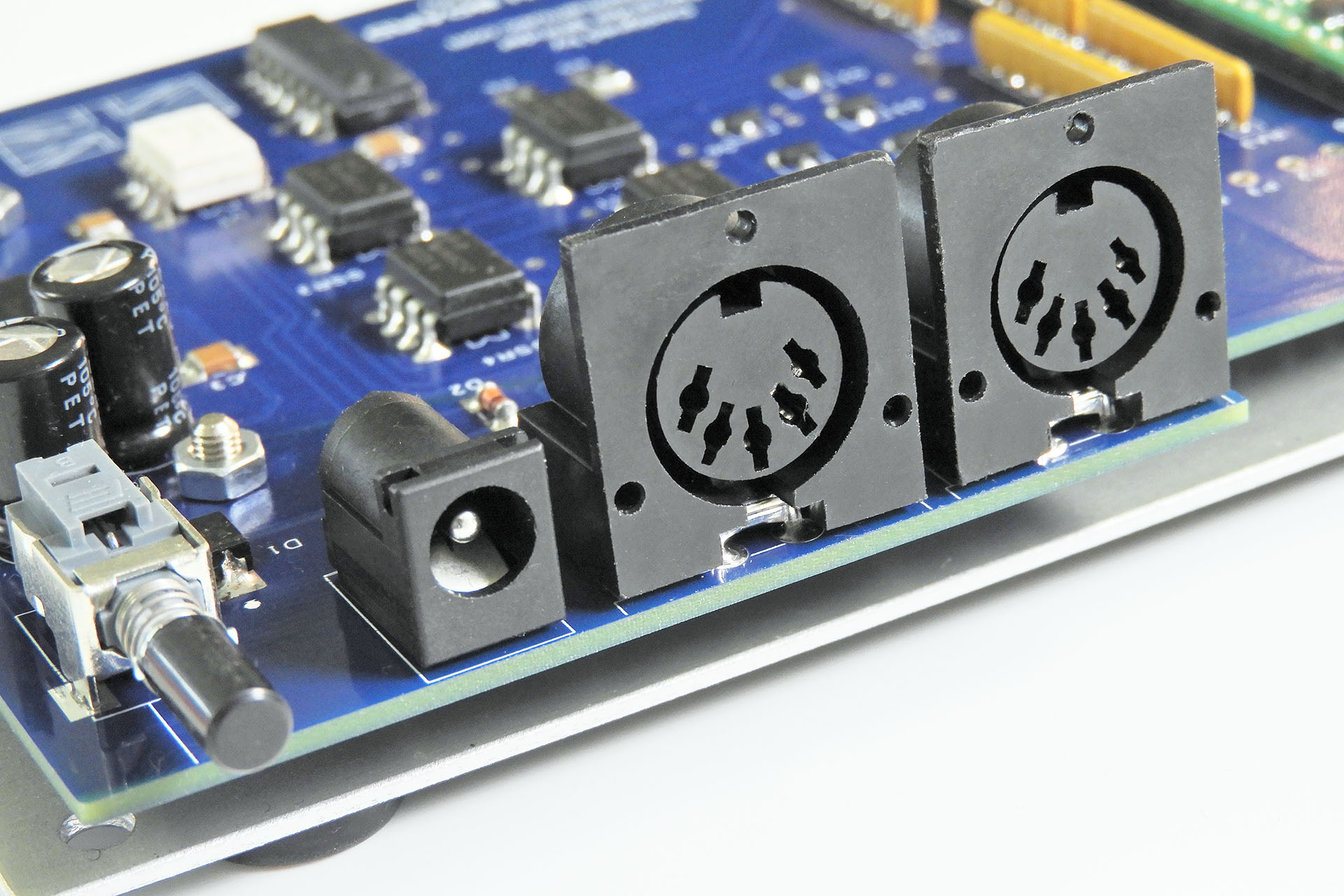
Here you can see the four dual SSRs (middle of image) and the the eight transistors that switch them (just a little up from middle of image).
Electromechanical relays would have cost more, potentially drawn more current and perhaps more importantly, they would have been much slower than optical ‘solid state’ devices so the reason to go for SSRs was clear.
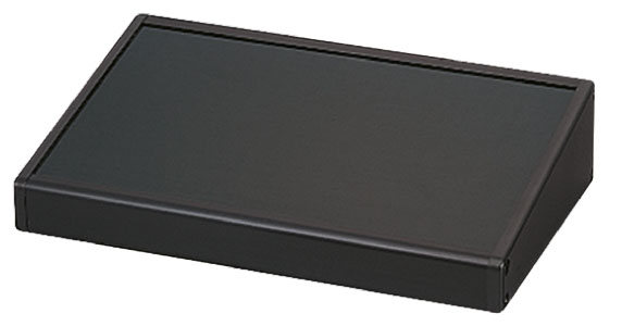
The next challenge was to find a suitable enclosure. There wasn’t much point to start designing PCBs if I didn’t know what they were going to go into. To be honest, I had a rough idea of the size of box required so I actually started looking for something back in November 2025, when I first had the idea of Gary.
The Takachi CF series of cases, specifically the CF16-11BB consistently came back as my favourite and one of my suppliers seemed to have this in stock so I bought one for prototype purposes. Yes, it was more expensive than I’d have liked but it was small, made from aluminium and readily available.
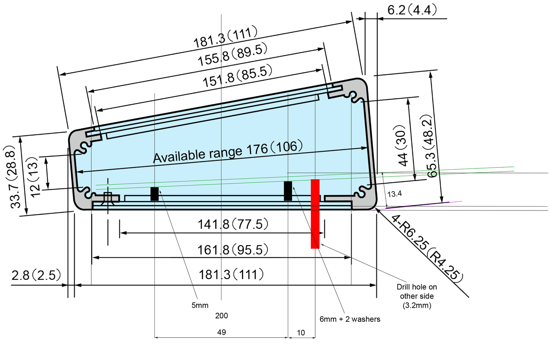
There was however, one very slight problem. The rear of the enclosure had a 10° slant from the vertical axis. To ensure that the rear sockets sat flush with the rear panel, I had to come up with a plan.
Lining up PCBs and rear sockets was particularly challenging with the Takachi CC16-11 case. As you can see, the rear of the enclosure is sloped. I superimposed my ideas over the original datasheet drawing after adding some dimensions which were missing.
You'll notice in the image above, that my 'plan' was to use slightly higher PCB stand-offs at the rear and slightly lower stand-offs at the front.
Despite lots of experience and all my best efforts, my first attempt at the Gary 7 enclosure had a couple of errors. The cut-outs for the switches were 1mm too big. I had to scrap the black anodised Takachi panel and get Lenton Engineering to make a new one from just plain aluminium.
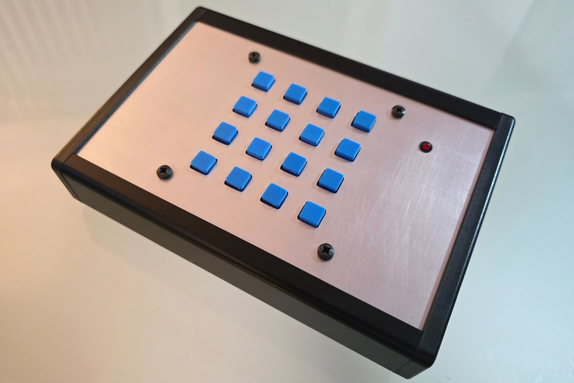
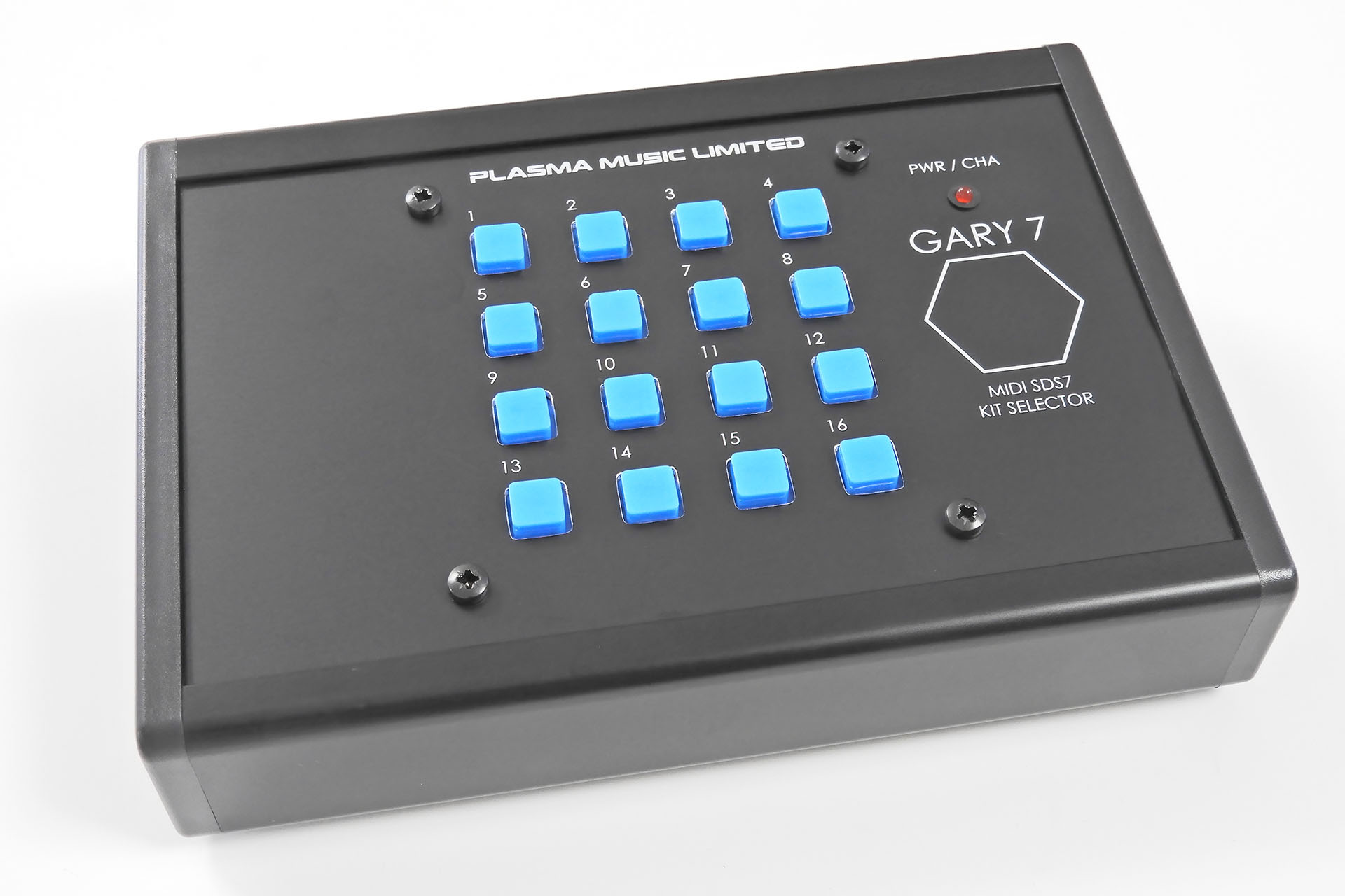
Gary 7 prototype top view. Not the top-panel that came with the enclosure as I originally made the tact-switch cut-outs 1mm larger than they had to be. Grr...
The other issue I had was down to the big multi-pin connectors on the rear panel. Basically, they were set too high. You can't see this too well in the image below but on the rear of the chassis mounting sockets, the securing nut butted into the top channel used for the side-screws of the enclosure. Lenton Engineering cut the channel but this wasn't the way to go, long term.
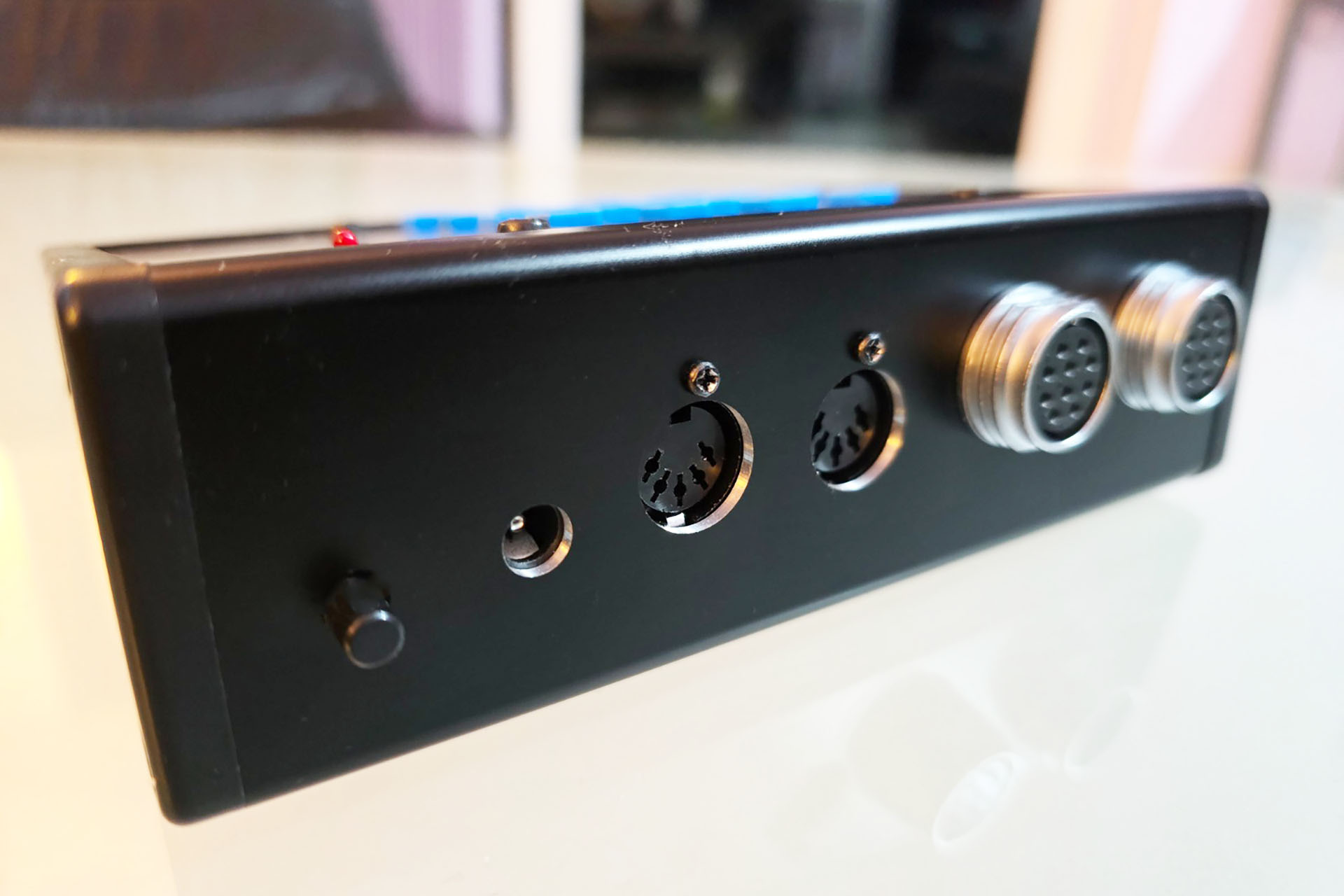
Gary 7 prototype rear view.
I got the switch-board right first time but the main-board had to be redesigned. I had to cut away a section of the PCB, specifically to the left of the MIDI sockets, so as to allow access to secure the chassis mounting multi-pin connectors.
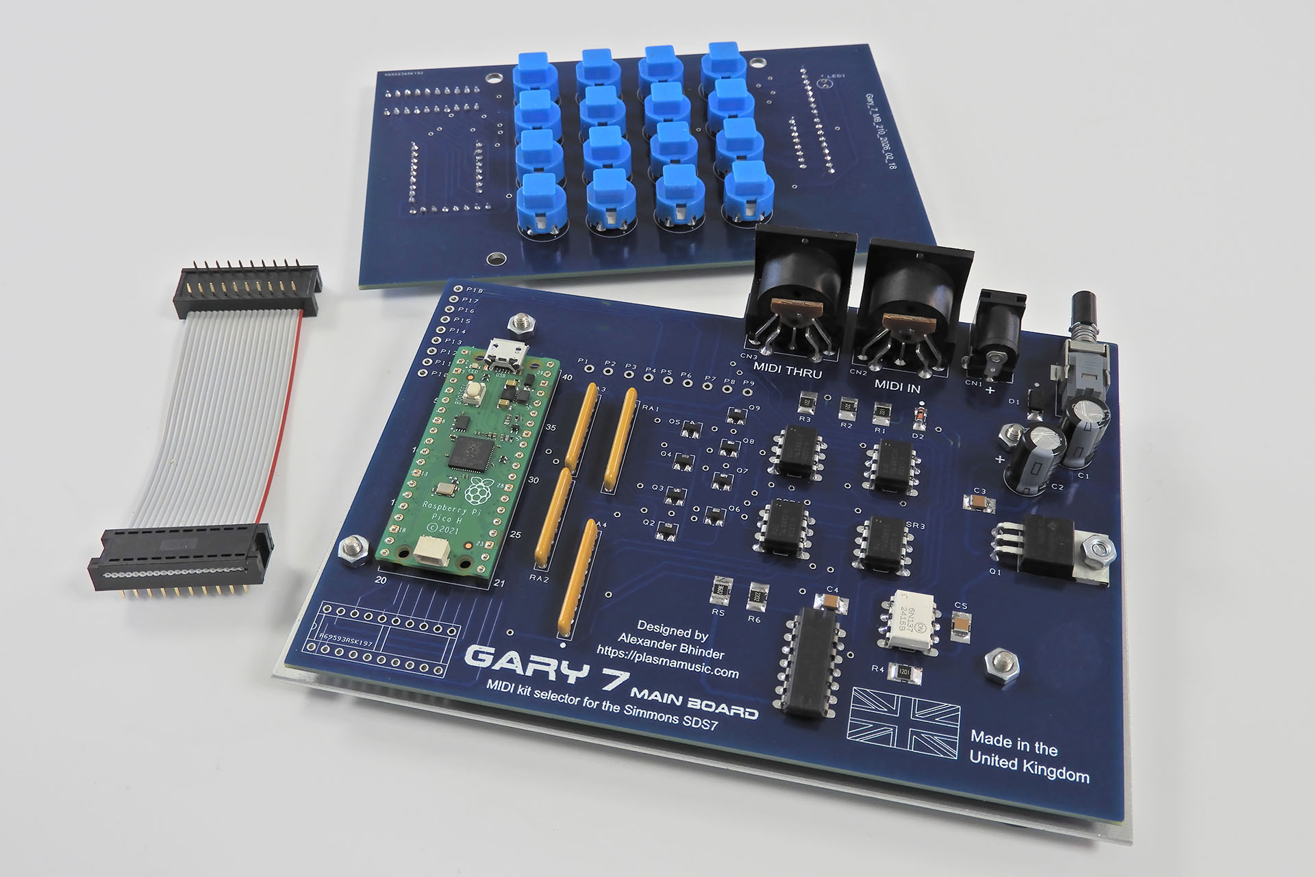
Here are the two Gary 7 PCBs: the switch-board and the main-board. Also shown is a 20-way IDC ribbon cable that connects the two.
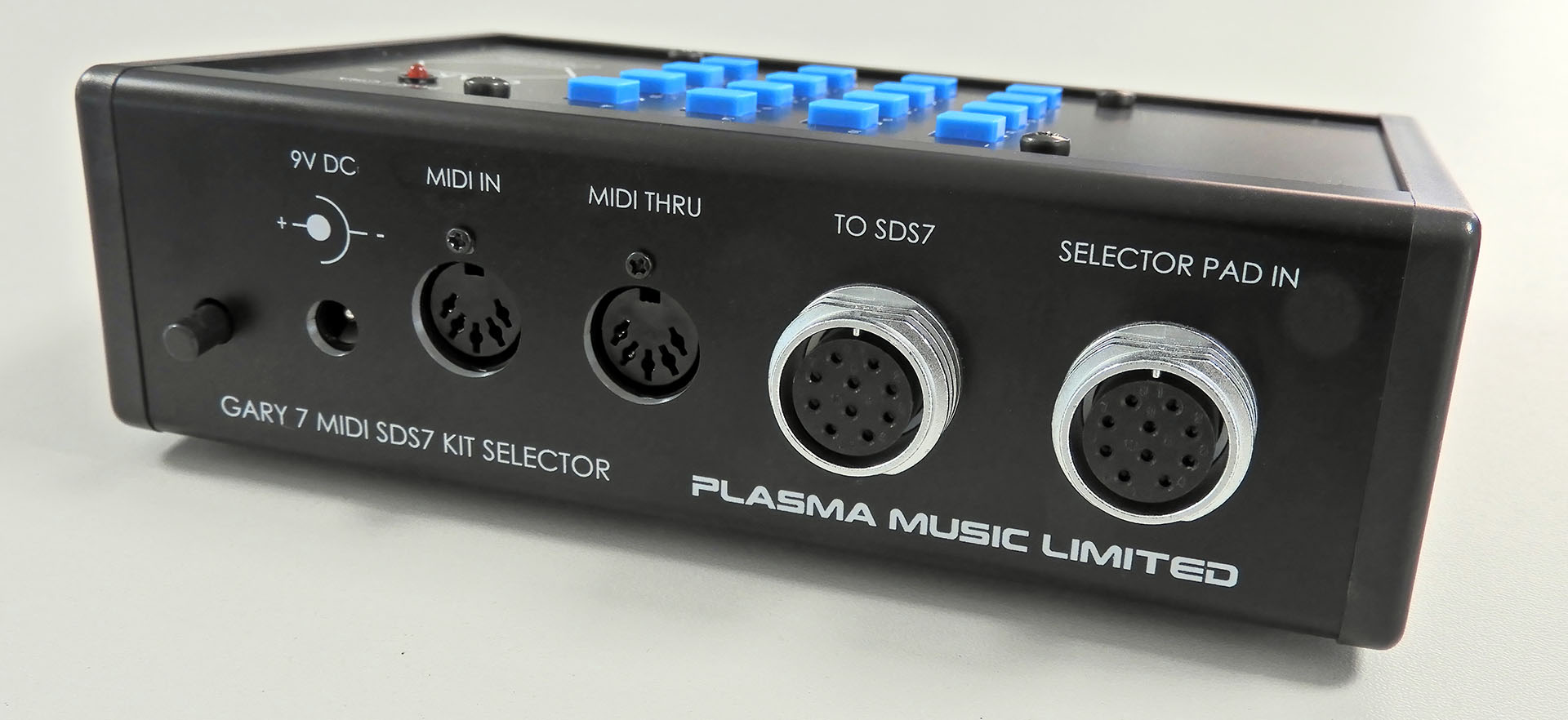
Power ON / OFF, power input (+9V DC) and MIDI are all soldered to the main-board while the multi-pin connectors to the SDS7 and the selector pad (if you have one) are chassis mounted. You may notice that the DC input and MIDI sockets look slightly lifted as if they're tilted. This is to help alignment of these sockets with the sloped rear of the enclosure.
What a pain in the butt but anyway... When the second drilled case components came back from Lenton Engineering, I couldn’t wait to see how things would fit together. Indeed this time, everything lined up perfectly and WOW... this is starting to look cool.
All the sockets and the power switch all lined up perfectly with the case.
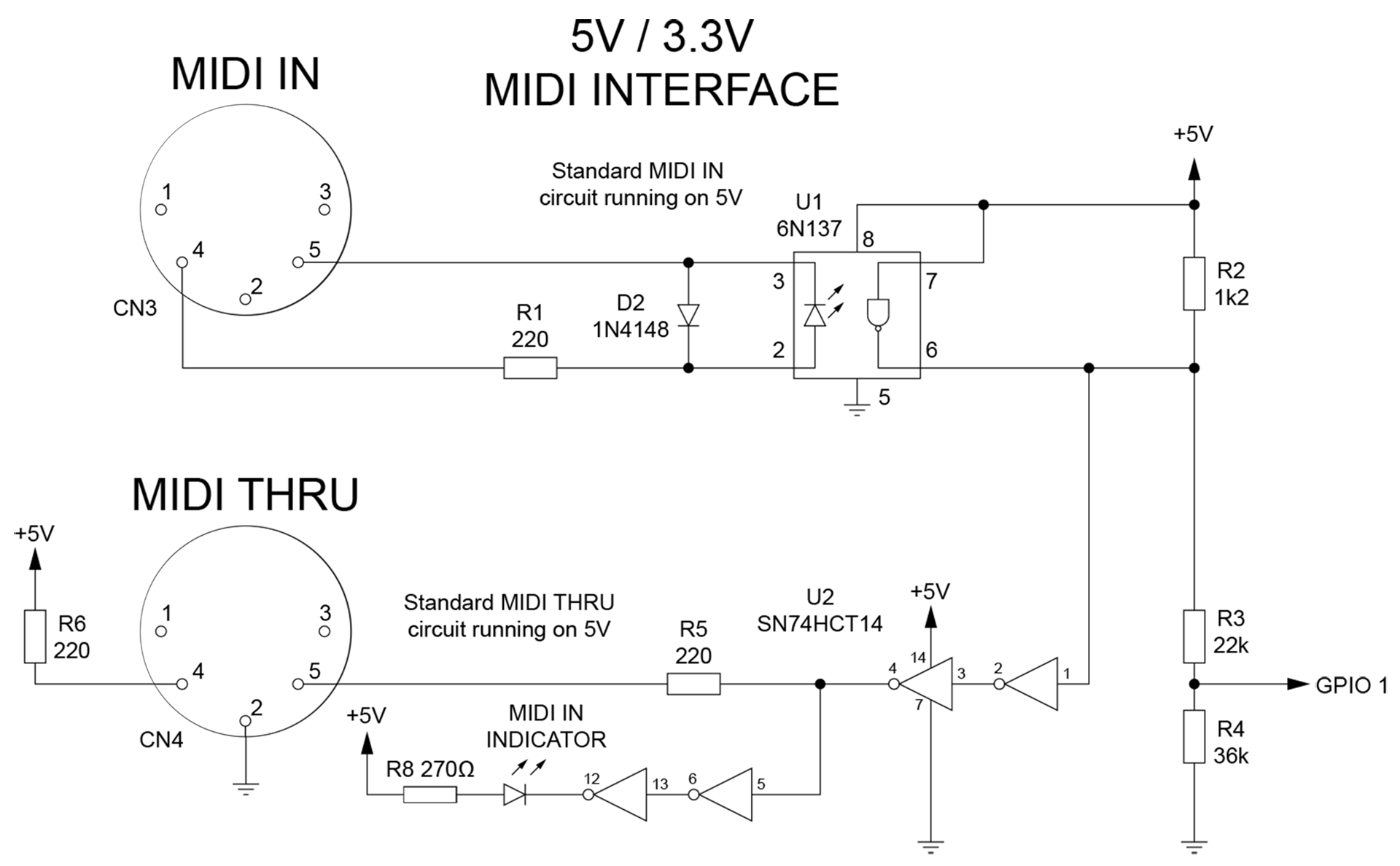
5V MIDI
Yes, I'm quite aware that 'modern' MIDI gear runs on +3.3V so as to interface with modern processors like for example, the Raspberry Pi but... I'm a strong advocate of backward compatibility and ensuring that the MIDI gear I design will work with anything, is a big deal for me. Customers should expect my MIDI products to work, they should take it for granted!
Here's the MIDI circuit from my Gary 7 development board. Gary 7's MIDI circuit is the same but without the MIDI indicator LED. As you can see 3,.3V MIDI IN for the Raspberry Pi is derived from a simple potential divider. It's just not difficult.
It really annoys me that many Internet gurus don't even acknowledge 5V MIDI. I'm the total opposite and to be honest, having 5V at the MIDI ports isn't a difficult thing to do anyway. As such, Gary 7 has a traditional (albeit much faster) MIDI circuit that's configured around 5v and which is fully backwardly compatible.
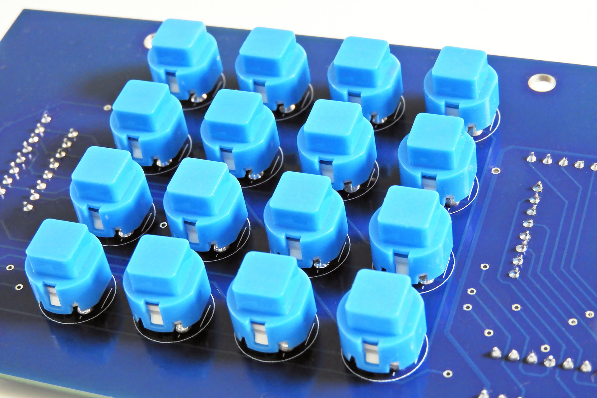
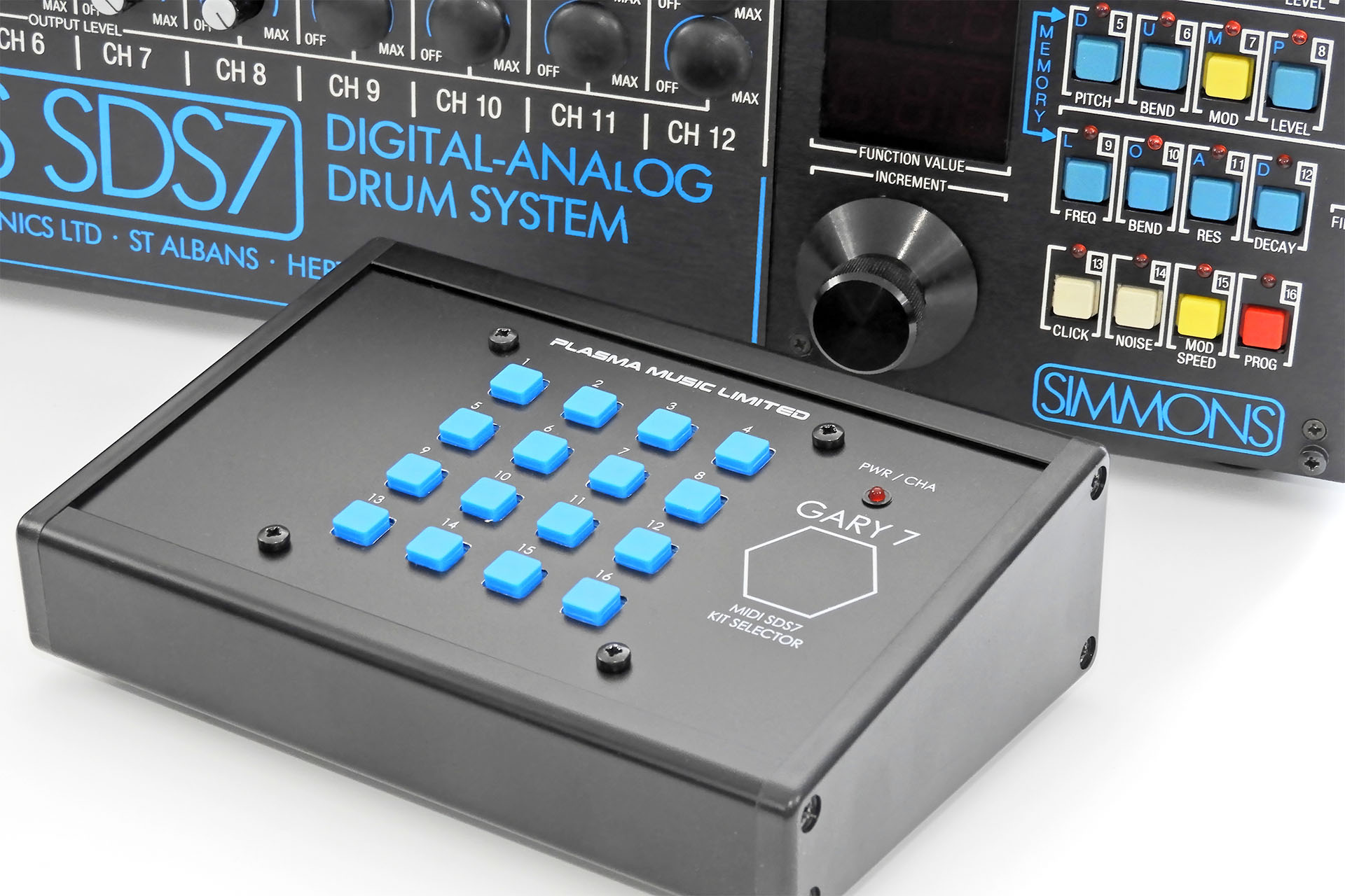
It's difficult to make a peripheral more than forty years after the original product was launched and keep a design connection with that product. I did try, though and having Simmons style switches was exactly the retro connection I was looking for.
Gary 7 has the same style of switches as Simmons used on the SDS7, over forty years ago.
With the PCB, multi-pin sockets and enclosure all fitting nicely, I sent a set of silk screen print files to my friend Ivor Mitchell. Ivor dropped round a couple of days later to pick up the case parts. It was only a few days later when Ivor returned with the job. I was delighted and rushed to get the electronics into the now very sexy looking case.
I've never been patient but the time it took to get Gary 7 to this stage seemed like a particularly long wait. Having said that, my friend Ivor did a fantastic silk screening job, adding the final touch.
I had to buy another enclosure and recut the rear panel, lowering the multi-pin connector sockets by only 2mm.
Rear of Gary 7 final with everything fitting much better than my prototype and looking like a finished product.
Gary 7 MIDI kit selector for the Simmons SDS7 ended up being a BIG little project. My first project involving software, my first for which I made a bespoke development board and the first time I'd used AI for anything, it was seriously fun!
Gary 7offers three ways to select kits on the SDS7:
MIDI program change
Manually via the sixteen on-board buttons
An original Simmons kit selector pad
As well as being able to set the MIDI channel on Gary 7, the last MIDI program change or last button press on the front panel will be remembered and output to the connected SDS7 five seconds after the next power-up. The 'Last Command' feature will NOT remember the last pad hit on a connected Simmons kit selector pad. That's because the selector pad input and the connection to the SDS7 are simply paralleled. The pad input does not pass through the processor so any signals received from the selector pad, can't be written to memory.
THE DOWN-SIDE - GARY 7 IS EXPENSIVE! 😕
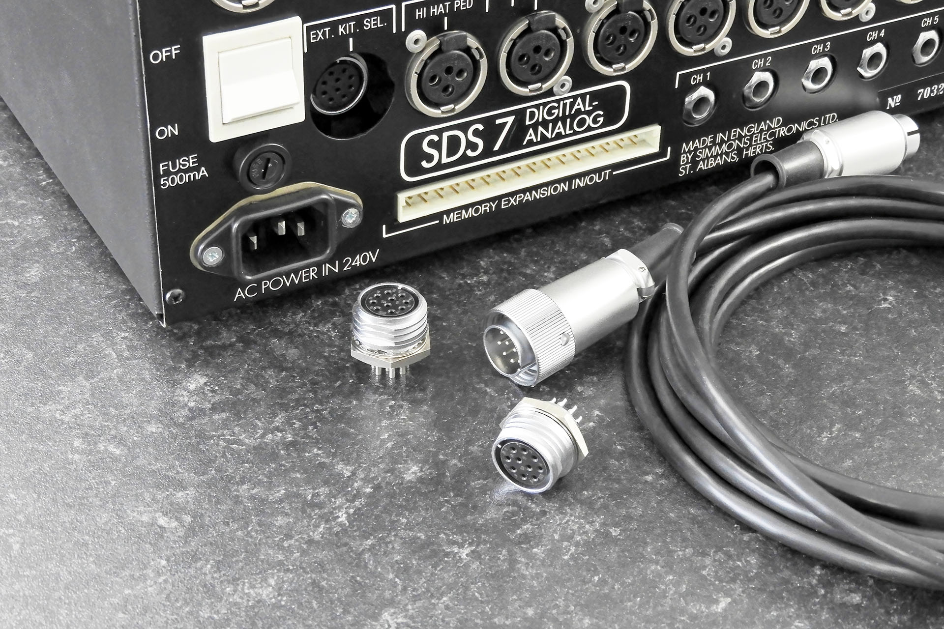
On the back of Gary 7 are a pair of female connectors, identical to the selector pad input that's on the back of the SDS7. One connects to the SDS7 and one is for connection of an original Simmons selector pad. There’s also a cable to connect Gary 7 to the SDS7. This cable has two male connectors, one at each end. At the time of writing, just those four connectors alone are over 72 GBP.
Shown are the connectors as used for the kit selector pad connection on the Simmons SDS7.
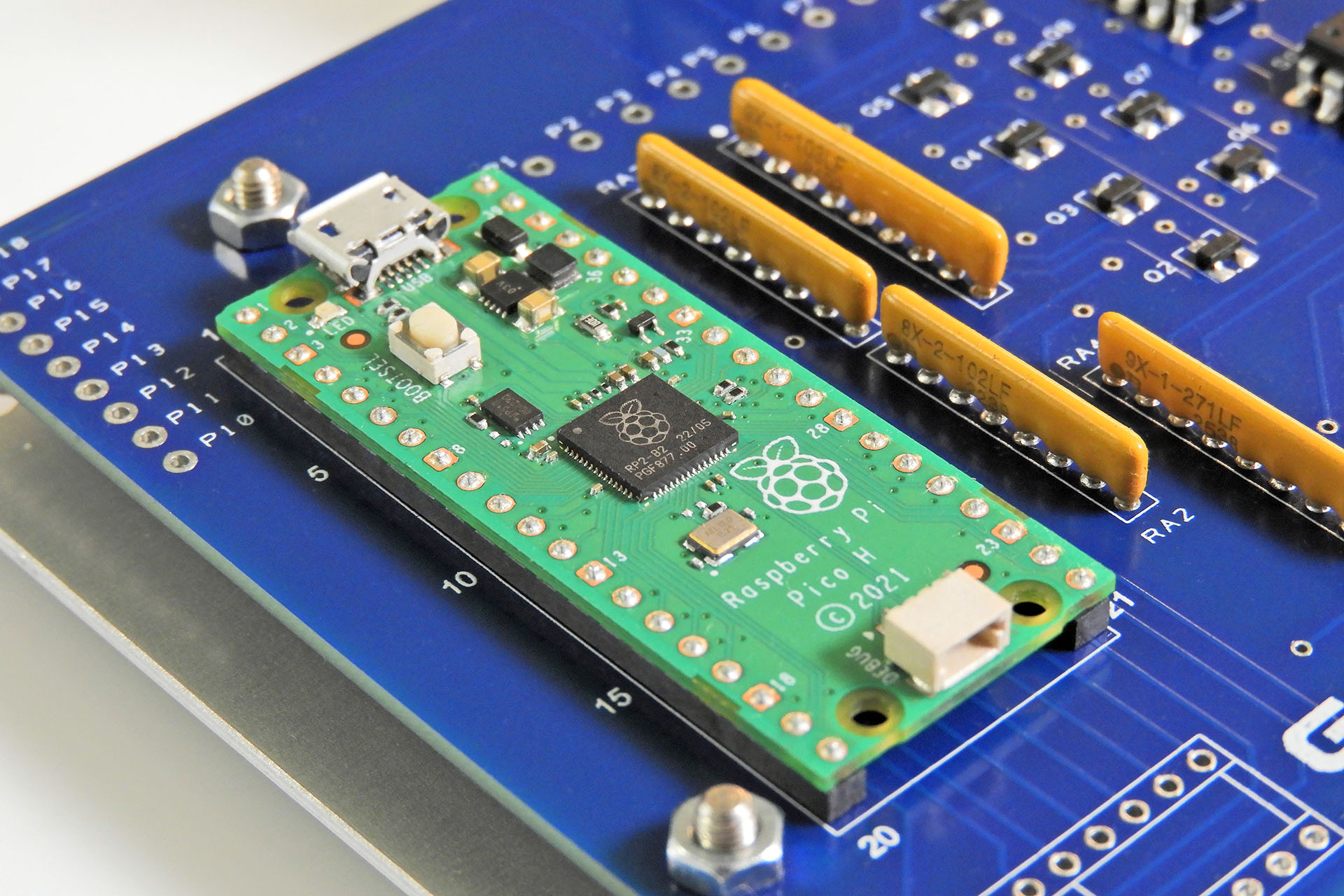
In contrast, the heart of the system, the Raspberry Pi Pico (with headers) retails in the UK for just under 5GBP!
At the heart of Gary 7 is a Raspberry Pi Pico costing less than 5 GBP.
Incidentally, in the image above that shows the connectors, take a closer look at the cable that connects Gary 7 to the SDS7. You'll notice that there's a ring around one of the connectors. This 'locking' ring is supplied by the manufacturer, with the connector. If you have a Simmons selector pad, you'll be aware that this ring is (blatantly) absent. That's because the socket on the SDS7 is recessed and unfortunately, Simmons didn't make the cut-out in the rear of the SDS7 big enough, thus making the locking ring almost impossible to comfortably access. 😕 This connector on Gary is mounted directly to the rear panel and therefore, NOT recessed. As such, I decided to include the locking ring to make things secure at the Gary 7 end of the connection. Trying to fit the connector with the locking ring to the SDS7, might be difficult!
Anyway, back to the expensive Gary 7... The Takachi CF16-11BB enclosure is pretty cool but at more than 30 GBP each, suddenly it's not so cool. Bear in mind that I have to get it drilled out and then silk-screened.
These guys look made for each other!
A WORD ON AI
The truth is that since this whole AI thing kicked off, I haven't exactly been keen. When I look back however, I was never a fan of having computers in the recording studio, LOL. Of course, it soon became obvious that computers in the studio was the way it was going back in the nineties and in contrast, AI is the way that everything's going now. NO! That's not quite true and there's a lot more to it than that.
I have a lot of test equipment in my lab. I have a couple of oscilloscopes, signal generators, logic analysers. I have over 2500 GBP worth of state-of the-art soldering equipment. And I've never argued that I shouldn't have any of that. All that gear helps me fix music technology and design and build some really cool stuff.
Similarly, I use two computers in my recording studio. Both computers run the most amazing software. The music that comes out of my studio however, is still mine. The computers just help me get it out.
My decision to use AI as an aid to develop the software for Gary 7 was based on the firm commitment that AI would be strictly used as just another tool. Like any other piece of equipment in my lab and like the computers in my studio, my intention from the outset was to use AI to help me develop something specific and not to get it done for me.
GIVING A LITTLE BACK
I've mentioned how Gary 7 kept me occupied and my mind distracted while I dealt with my prostate cancer diagnosis. In the UK, one in eight men will develop the disease and while the treatment I received was quite simply amazing and the staff who looked after me were angels, I feel that more needs to be done. Wouldn't it be just perfect if I could help in some way?
I have therefore made the decision to DONATE ALL PROCEEDS from Gary 7 sales to prostate cancer research. Since I'm in the UK, the specific charity that I'm choosing to support is Prostate Cancer UK.
GARY 7 CREDITS
I repair and service a wide range of music technology from valve amps to analogue and digital synthesiser and signal processors. I also design and manufacture peripherals for a lot of this equipment. It can get a bit lonely. I don't mean that I feel 'alone', I mean that there's just no way I can know everything. Having people I can talk to is a big deal for me and as well as having the best customers in the world, I'm also very lucky to know some great techs and engineers. 😊
CONCEPT: Alexander Bhinder INSPIRATION: Iain Melville, Mike Walden HARDWARE DESIGN: Alexander Bhinder PROMPTS: Alexander Bhinder SOFTWARE:Microsoft Copilot TESTING: Alexander Bhinder ENCLOSURE DESIGN: Alexander Bhinder ENCLOSURE CUTTING: Paul at Lenton Engineering SILK SCREENING: Ivor Mitchell at S & S Quality Print CHEERING ME ON: Ed Rose, Micha Buchner, Patrice Jacquot (my Simmons Vintage Technical Network buddies).
Gary 7 joins my other peripherals and upgrades for the Simmons SDS7 in the Simmons SDS7 Heaven category in my on-line store. Can't wait? You can buy Gary 7 here:
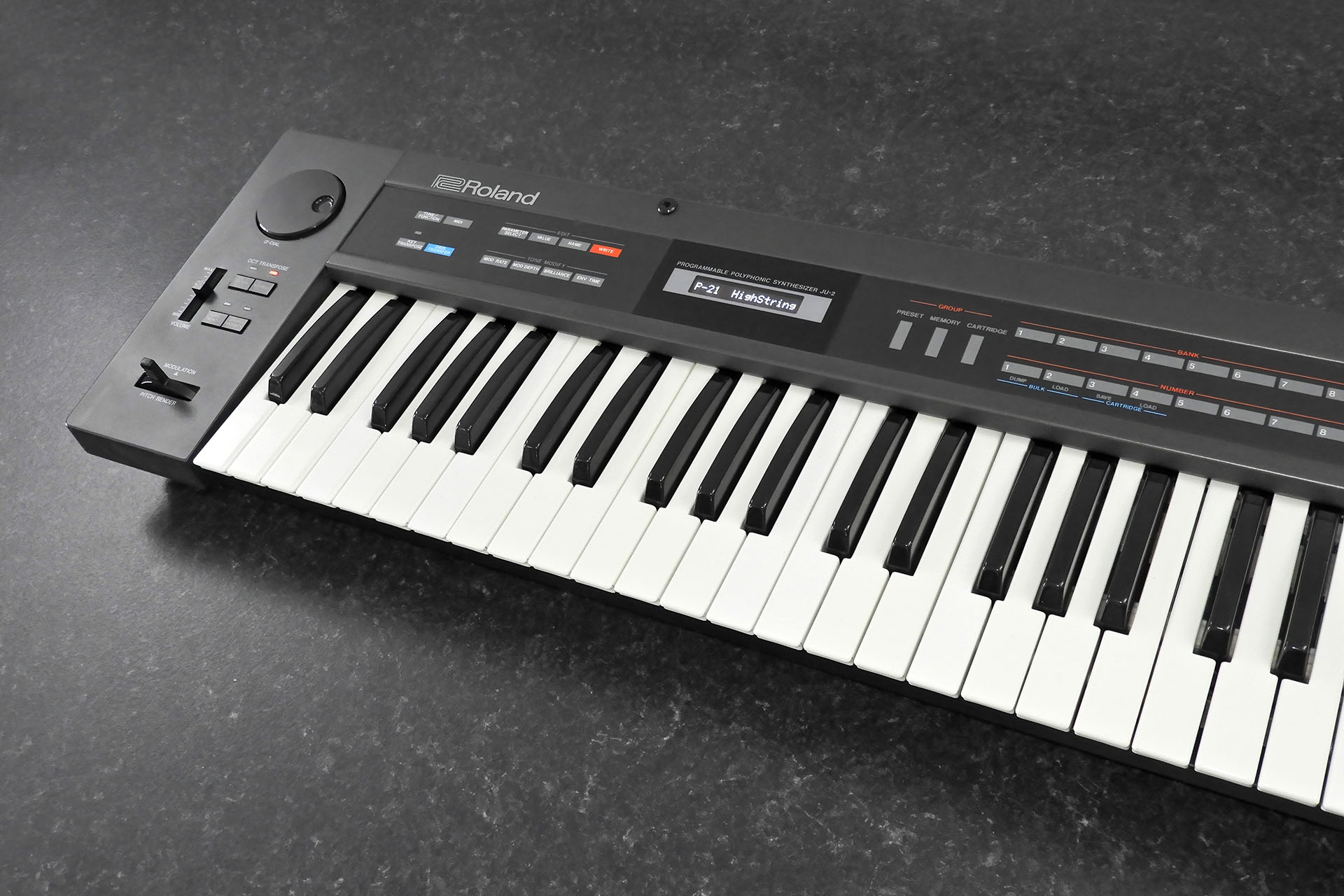
The original jack-board in the Roland JX-10 did its job really well but... it's time for something new.
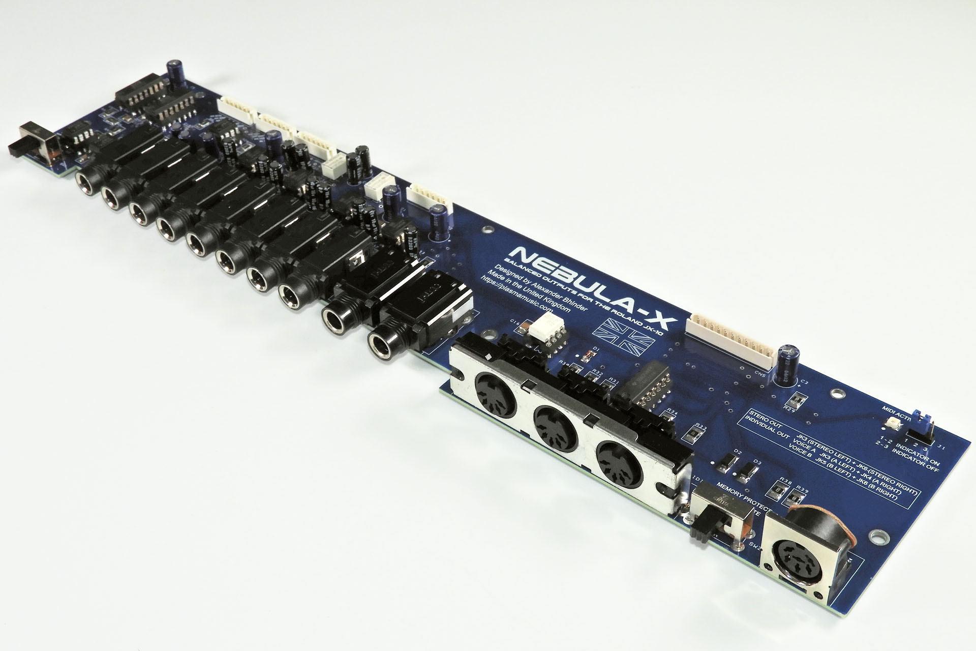
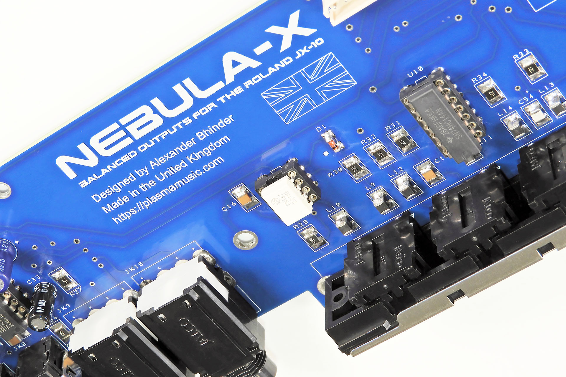
After a few years in the making, I’m delighted to announce that Nebula-X balanced outputs for the Roland JX-10 is finally here.
Soon after launching Nebula balanced outputs for the Roland MKS-70 back in Summer 2021, I received enquiries asking if I had plans to do something similar for the Roland JX-10. I took all those enquiries onboard and considered a replacement JX-10 jack-board with balanced outputs but the challenges were simply too much for me to pursue this kind of project at the time.
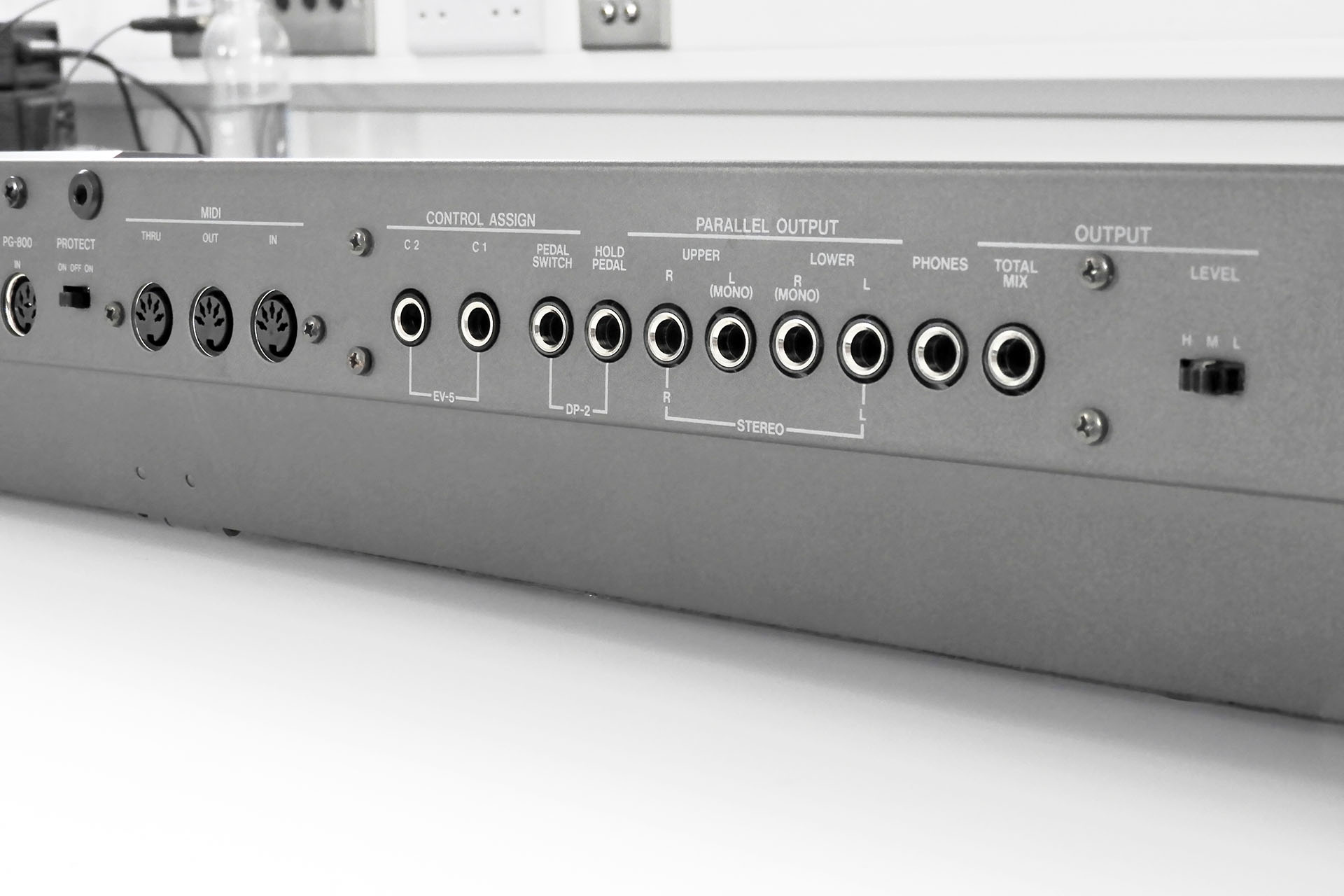
The JX-10 is a performance synthesiser and as such, it has a lot more sockets than the MKS-70. The JX-10 jack-board also hosts the programmer port and the headphone socket. Oh and one last thing, while I had three MKS-70s, I didn’t have a JX-10! 😒
I continued to receive enquiries and so a version of Nebula for the JX-10 remained in the back of my mind for a couple of years until I had an idea to potentially kill two birds with one stone.
Balanced lines drastically reduce noise between the outputs of one device and the inputs of another. In the JX-10 however, there’s an annoying noise source inside the actual keyboard. The audio connections between the module-boards and the jack-board run straight underneath the very noisy display. Noise picked up by those lines was enough to make Roland use screened cables for those connections, something that wasn’t deemed necessary in the MKS-70, as the layout is quite different. If I could find a way to mitigate internal noise, that would give a replacement jack-board for the JX-10, something that would make a real difference.
So how was I going to achieve a better noise performance? Allow me to digress slightly to explain how this might be possible…
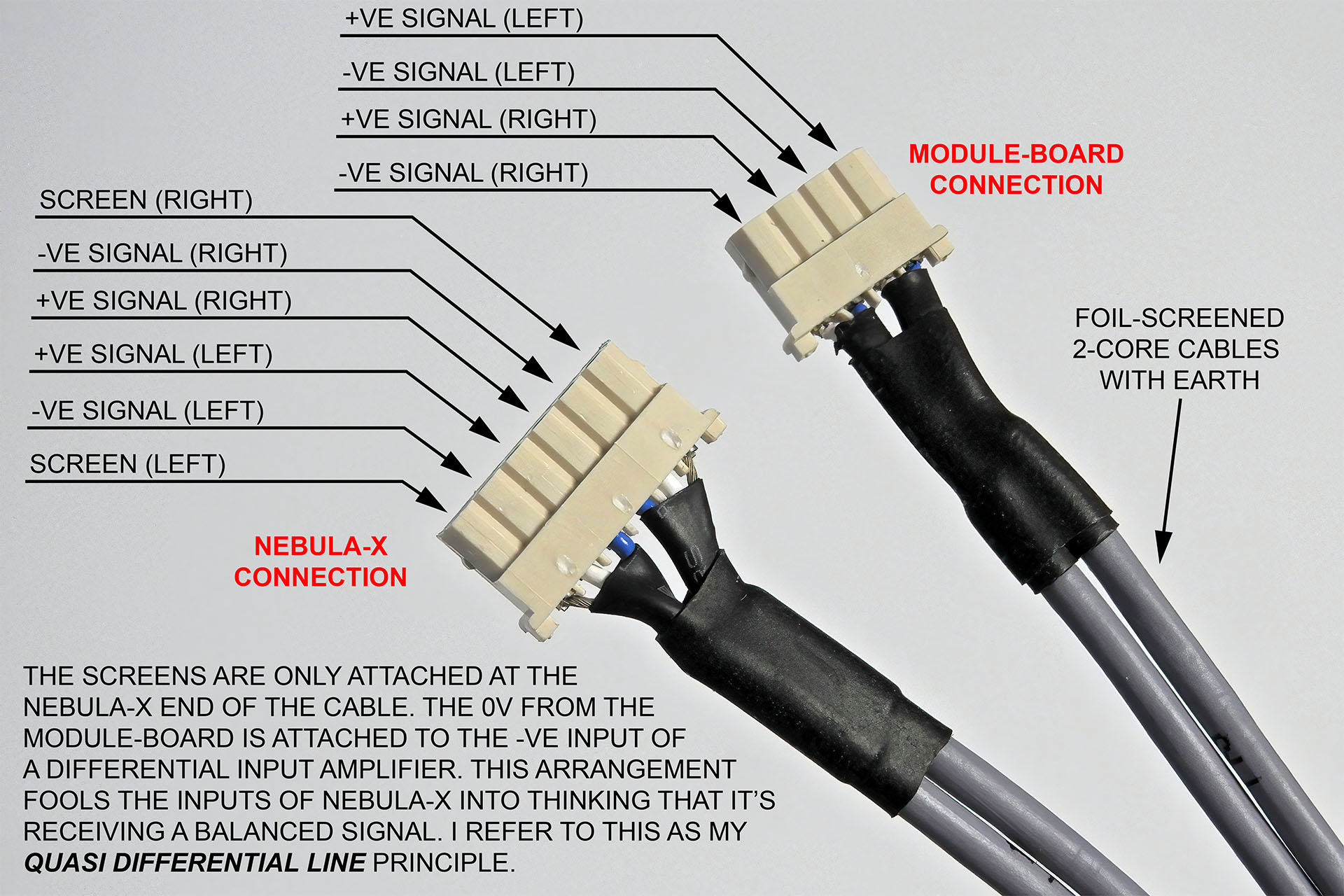
When I was a student in the early eighties and getting my first studio together, the lack of funds often pushed me into thinking outside the box. To reduce noise without balanced lines for example, I used something which I referred to as ‘quasi-differential’ transmission. My mixing desk had balanced inputs but most of my gear didn’t have balanced outputs. Normally, we’d just tie the inverting pin in the connector at the balanced input, to the screen (ground). If however, we use a screened 2-core cable with one core connected to the signal pole of the sending machine and the second core connected to the ground of the sending machine but we don’t join the second core to the screen, then the common rejection feature of the balanced input of the receiving machine would remove noise as if the line was balanced… kind of. Using this principle was in my opinion, something worth experimenting with and suddenly Nebula-X balanced outputs for the Roland JX-10 looked like a worthwhile exercise.
You may have noticed that to do this trick, a screened 2-core cable will be required. Quasi-differential transmission can’t be done with a screened single core cable. Those familiar with the inside of the JX-10 will be aware that the lines connecting the module-boards to the jack-board, are screened single-core cables so YES, new cables will be required but don’t worry, I figured that these should be supplied with Nebula-X.
On top of that, while there’s a 4-pole connector at the mod end of the audio lines in a standard JX-10, the audio connections on Nebula-X are 6-pole as each module-board connection will require two sets of signal, 0V and screen.
Here's an example of the kind of cables that are supplied with Nebula-X. Notice the 4-pole Molex that connects to the module-board and the 6-pole Molex that connects to Nebula. Notice that the screen in each core is only connected on the 6-pole connector (Nebula-X).
This was looking like a really cool solution. Yeah okay, the audio cables will need to be replaced but no modification to the audio output connectors on the module-boards would be required.
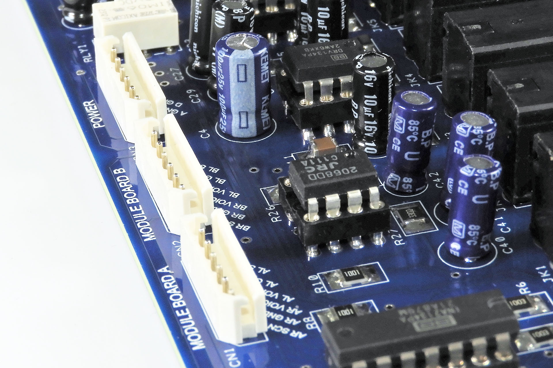
The two audio signals from each module-board come in via a pair of 6-pole connectors and NOT the expected 4-pole versions.
So how does this quasi-differential system work?
Well, we kind of use the second core in the cable, the core that's connected to ground at the module-board and goes into the inverting input of one of Nebula-X's differential amplifiers, as bait. We actually want this core to pick up noise!
You see, both the signal carrying core and the 'second' core go into a differential amplifier with the former connected to the non-inverting input and the latter connected to the inverting input. The differential amplifier does its job and rejects, or filters all signals that are common on both inputs. The only common signal is of course, noise since noise hits everything in the same way and doesn't give two hoots if one line is inverting and another is non-inverting.
Do be warned, however. A balanced line CANNOT get rid of noise that's already in the source. Any noise generated on the module-boards for example, won't be filtered out.
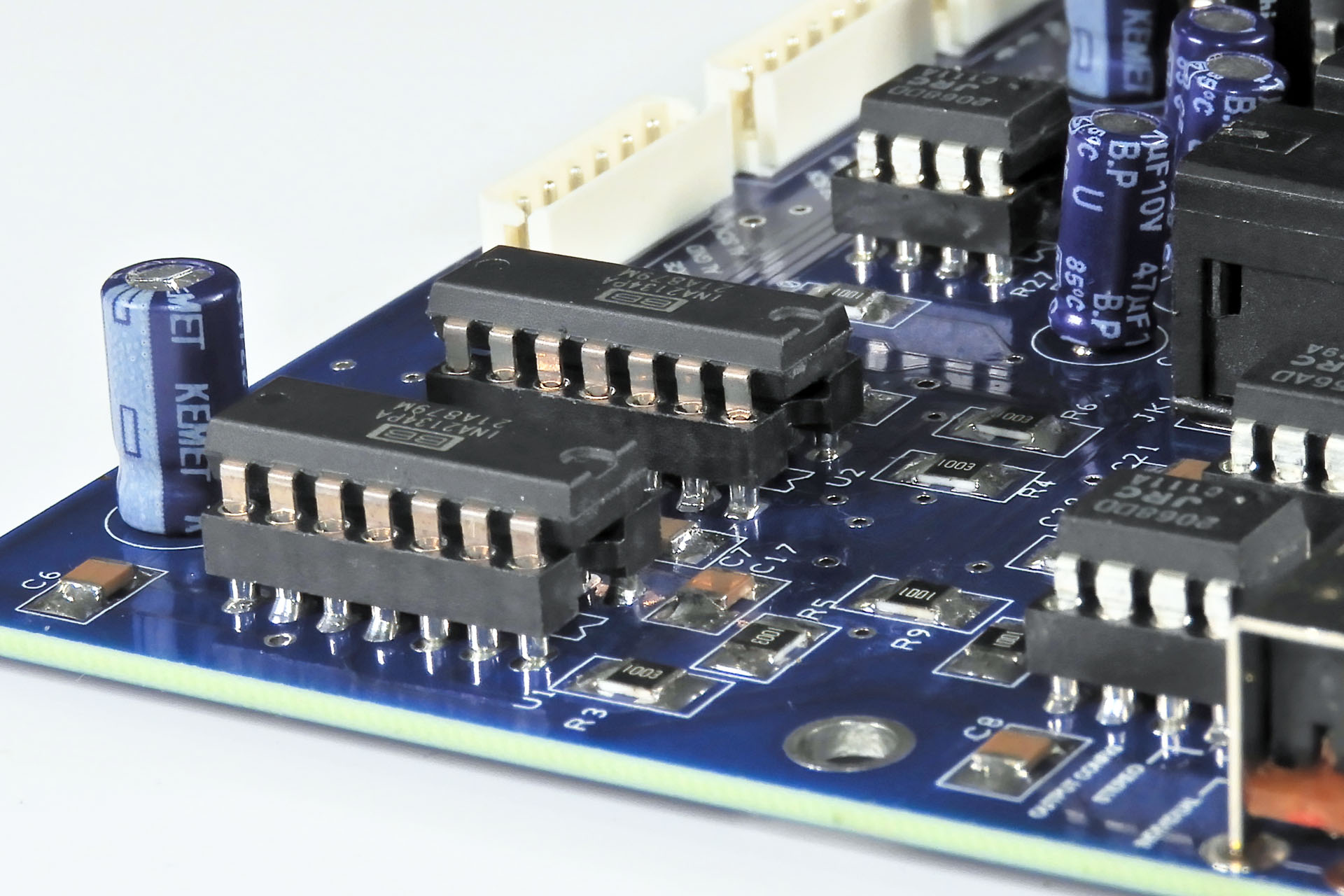
And YES, I'm glad you've worked it out and you’re absolutely correct; to implement my quasi-differential line trick, as well as having balanced outputs, Nebula-X also has balanced inputs. I actually used the INA2134 by Texas Instruments which is an insanely high-specification device.
A pair of INA2134s provide Nebula with four balanced inputs.
Other than having balanced inputs and a bunch of sockets that aren’t on the MKS-70 jack-board, Nebula-X inherits all the principles that I used on Nebula. Apart from fulfilling the main objective, Nebula-X has revised, more robust MIDI hardware, a MIDI LED indicator (to show MIDI IN) and socketed ICs allowing the user to easily change devices .
Just like Nebula for the MKS-70, Nebula-X has a MIDI IN indicator.
Removing the original jack-board can be a bit tricky but with a little patience, it’s far from impossible. A long crosshead screwdriver with a long thin shaft is really helpful.
As mentioned, the original audio lines from the module-boards going to the jack-board, need to be removed or at least disconnected at the module-board ends as well as the jack-board end. The reason I mention that they should at least be disconnected, is that I like my upgrades to be easily reversable. In fact, I absolutely hate the idea of upgrades or modifications that require permanently compromising beautiful vintage equipment and that’s why ALL my upgrades can easily be removed and equipment and respective gear returned to its factory sate.
As with Nebula, designing Nebula-X balanced outputs for the Roland JX-10, required a couple of workarounds which in my opinion, were acceptable compromises.
Roland implemented an ingenious switching system which allowed for automatic voice output selection, depending on which output sockets had jack plugs in them. Doing something similar with Nebula and Nebula-X was impossible for one reason and one reason only: space.
As per the original JX-10 jack-board, the pedal inputs on Nebula-X are also switched ‘stereo’ sockets. This is necessary for pedals to work properly and so that the JX-10 switches to C1 and C2 control when no pedals are connected to the jack sockets. Anyway, being much wider than mono switched or stereo unswitched sockets, they simply wouldn’t fit in the locations of the voice-output sockets.
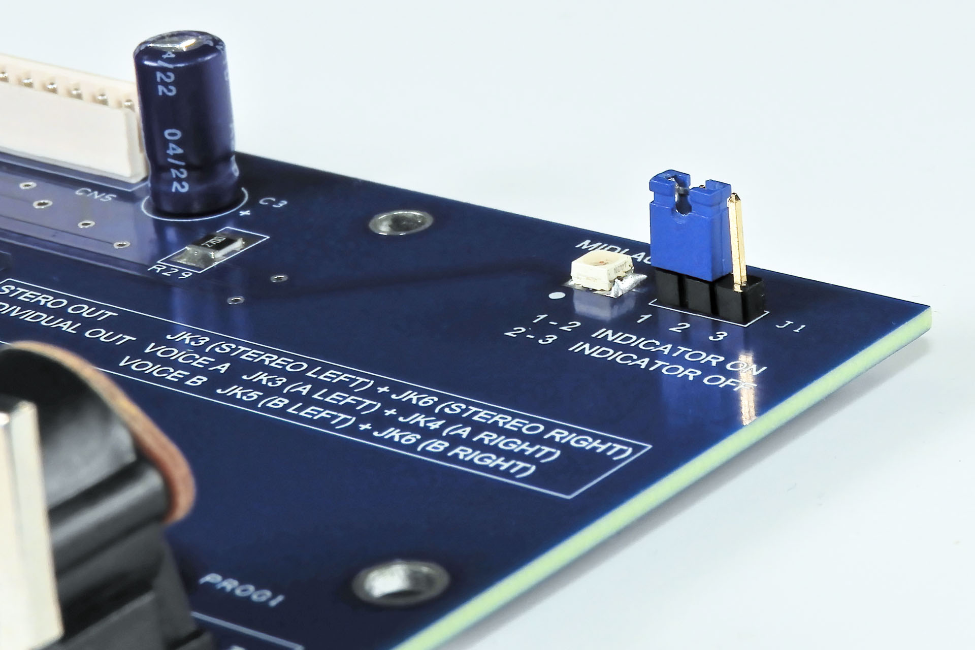
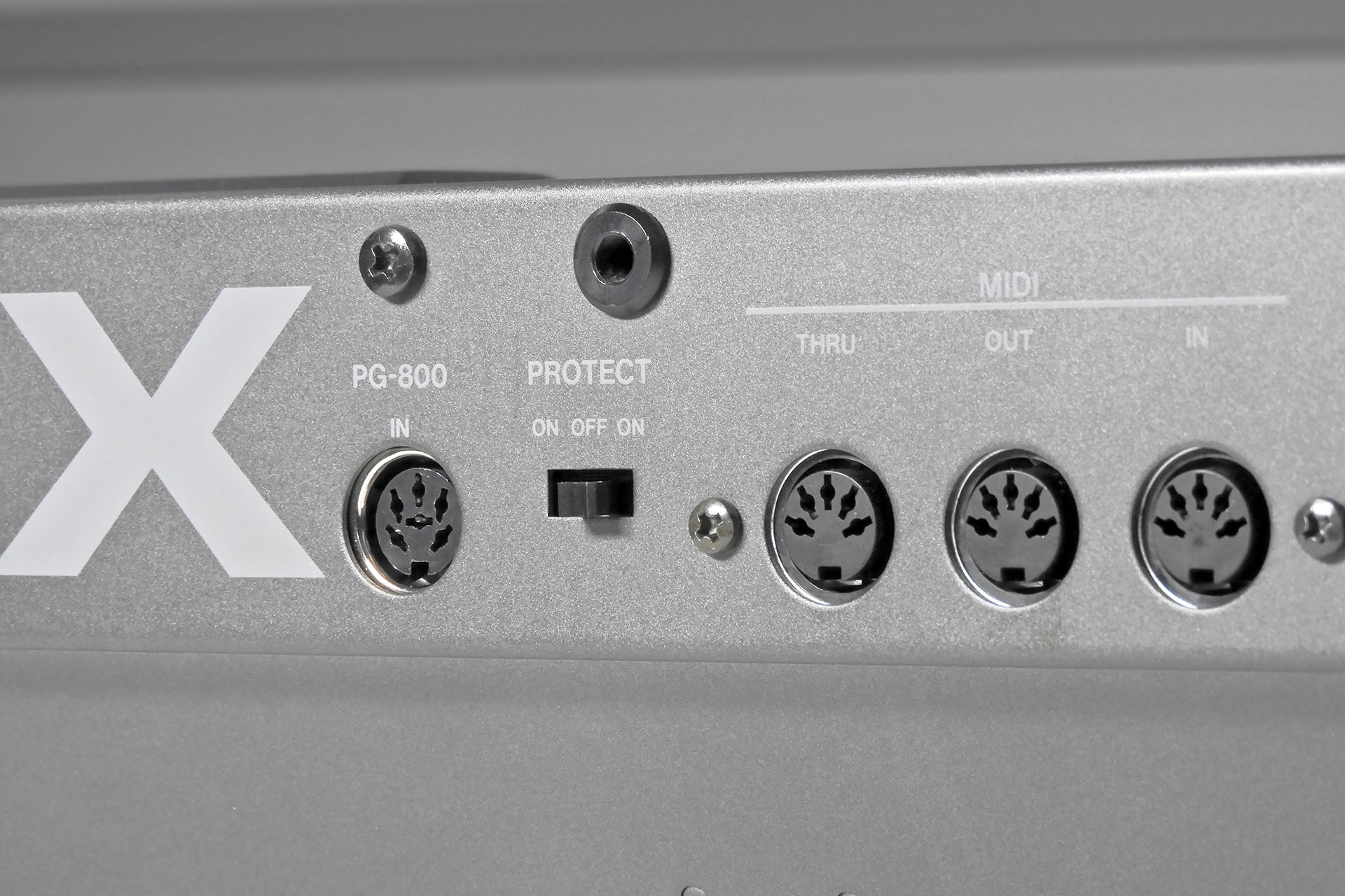
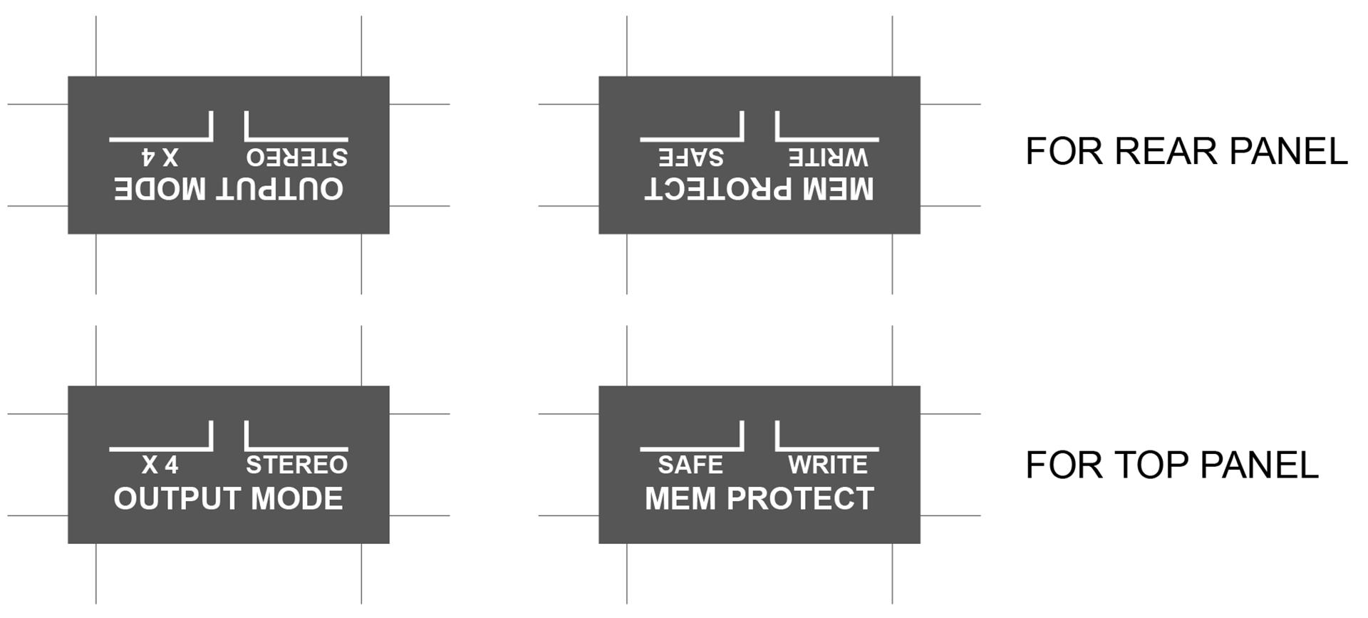
As such, the level selector switch for the mono output has been replaced with a switch that changes the output configuration of Nebula-X from stereo to four independent outputs.
Finding a suitable switch was a challenge which began with the design of Nebula. Something else to bear in mind is that the memory protection switch on the MKS-70 is on the front panel so I didn’t need an ON-OFF-ON (3-position) switch on Nebula. All I needed was an ON-OFF switch to energise a couple of relays to switch the output mode. Nebula-X however, did have to accommodate a memory protection switch.
Unfortunately, despite my best efforts, I couldn’t get an ON-OFF-ON version of the switch I used on Nebula for the MKS-70. 😡 Hence, the memory protection switch on Nebula-X doesn’t have a ‘centre’ (memory protection off) position.
I spent months looking for a 3-position horizontal slide switch that would be high enough to fit but my efforts were in vain. I had to make do with 2-poisition slide switches but personally, I consider it an acceptable compromise.
Nebula balanced outputs for the Roland MKS-70 is supplied with a label which goes on the back of the instrument, to remind users of the switch position for stereo and individual outputs.
Similarly, Nebula-X will be supplied with two (smaller) labels for output mode select and memory protection ON / OFF.
One of my philosophies when considering a new design, is to follow the old 80% planning and 20% doing rule. The first thing to consider, is whether or not the new project a worthwhile venture. As mentioned at the start of this post, initially I wasn’t able to convince myself that Nebula-X was worth the hassle. Designing the electronics doesn’t start with a blank schematic. One needs to work out if the new peripheral or modification will work with the host system. Since there are very obvious similarities between the JX-10 and the MKS-70 and bearing in mind that Nebula for the MKS-70 already has a proven track record, it seemed that Nebula-X balanced outputs for the Roland JX-10 would theoretically work.
The mechanical aspects of of a design are also important. There's no point designing cool bit of electronics if for example, it's not going to fit! In the case of Nebula-X, I wanted an easy drop-in design. That’s great but things like screw holes need to line up and sometimes that’s quite challenging when dealing with the types of tolerances in a machine that’s forty years old. Having said that, I do see machines like the Roland JX-10 in a slightly different light. It’s kind of amazing that Roland and other manufacturers were able to achieve such well-fitting panels with the technologies that were available in the eighties.
Nebula-X fits nicely into the JX-10.
Indeed, sometimes I feel that the electronics design work of a project is only a small percentage of the work that goes into it. When making peripherals for other manufacturers' equipment, it's important that they should fit. Everything must line up perfectly. A lot of thought went into Nebula-X. In fact, it kind of seems like it should always have been there!
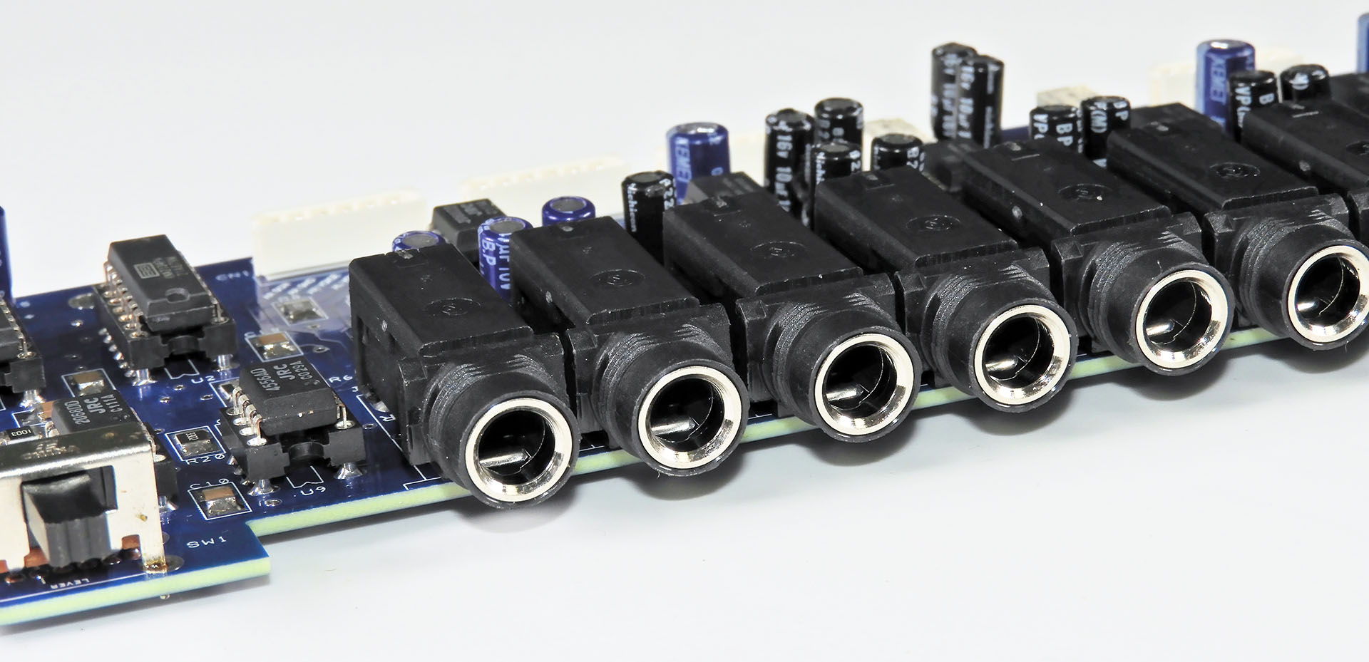
You'll notice that the jack sockets on Nebula-X have a chromed inner ring. I think they give the JX-10 a rather nice cosmetic touch. Once you get used to the new look, it's like Nebula-X should always have been there!
Briefly touched on earlier, finding suitable sockets was another challenge. Size and quality were obvious criteria but what about cost. With no idea how many Nebula-X systems will be sold, I needed to secure a source that will be reliable and offer me realistic prices.
All control port sockets like the two footswitch inputs, the pedal inputs and of course the programmer port, all function as they should.
Roland was keen that their instruments could be used live as well as in the studio so like the MKS-70, the JX-10 has a mono output that can be fed directly into an amplifier. I decided NOT to make this output balanced and set the output level to be compatible with most keyboard amps and combos... not that I imagine anyone taking their JX-10 down the pub for a Friday night gig!
Anyway, after all that, Nebula-X ended up fitting like a glove. Nebula-X literally became a drop-in design, exactly as I had intended and in my humble opinion, Nebula-X balanced outputs for the Roland JX-10 is an easy to install and worthwhile upgrade for the serious JX-10 user.
Every Nebula-X balanced outputs for the Roland JX-10 is hand-made by me in the United Kingdom.
One last point; balanced outputs are 6dB hotter than their unbalanced counterparts. That can only be a good thing.
All my products are accompanied with either an installation manual or a user guide. Nebula-X is no exception apart from the fact that I haven't written the installation instructions yet! 😕 While I'm getting the test results media together, I'll also be compiling detailed and fully illustrated instructions. Having said that, Nebula-X is pretty straight-forward to install. You just take out the old board and drop in the new. 😎 I guess replacing the two audio cables might be a bit fiddly. With no soldering required, Nebula-X is literally plug 'n' play!
UPDATE: 6th February 2026
NEBULA-X BALANCED OUTPUTS FOR THE ROLAND JX-10 PRE / POST NOISE TESTS
Of course, apart from wanting to satisfy my own curiosity, I don’t expect anyone to take my word for it. Although the theory is sound and indeed, I've used my quasi-differential system many times over the past few decades, I'm quite aware that my word might not be enough. So as soon as I can, I'll be posting some test results. Most likely in the form of a video, I'll record the outputs from my JX-10 with the original Roland jack-board and then with Nebula-X.
Before I show you the Nebula-X noise comparison test, it may be useful to look into the whole JX-10 and balanced line stuff in a little more detail.
Noise and hum from the display, are induced into the cables that connect the audio outputs from the module-boards to the jack-board. Roland tried to reduce the effect of this interference by screening those cables. One wonders just how noisy the JX-10 would have been if Roland hadn’t done that.
Unfortunately, Roland’s attempt to clean things up, didn’t go far enough. One of the objectives of Nebula-X was to see if another approach might do the trick. That approach involves putting my quasi-differential line theory into practice. I’ve already talked about the physical implementation of quasi-differential line theory but understanding a little of the physics, might also help understand my decision to consider this somewhat radical approach.
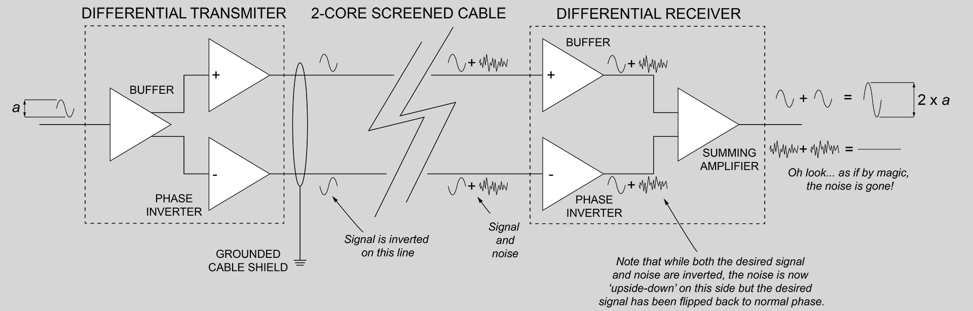
So balanced transmitter sends out tow signals; one is an exact duplicate of the input. The other is also an exact duplicate of the input with one exception, it’s upside-down, or 180° out of phase to the input and hence, also with respect to the other (in-phase) output.
Now let’s look at the transmission line itself. Two conductors carrying the same signal except one’s got the same phase as the original and the other is 180° with the original. Both conductors are in a screen which is usually attached to 0V or ground, at both ends.
Noise and hum induced into the cable that’s carrying the two conductors hits both of those conductors in the same way. The parameter of the noise that we’re interested in, is phase and the phase of the noise on both conductors is the same.
The receiver takes both non-inverted and inverted signals. The non-inverted signal passes though a buffer but just like in the sending device, the inverted signal is inverted again, putting it back in phase with the original signal. Oh but wait a minute… the noise on that line is also inverted and is now 180° out of phase to the noise on the other line.
The next part of the process is to mix the the stuff that's on the two signal lines. When we do this, the noise on one side and now the inverted noise on the other side, cancel each other out. That’s the fundamental theory of balanced line transmission.
Simple Mr. Bond but brilliant.
In the image above, you may notice something that turns out to be a curious but beneficial side effect of the balanced line transmission process and which occurs in the summing of the two lines (in-phase, out-of-phase) in the differential receiver. Since the two lines are summed, the signal that we want, ends up being twice the amplitude of the original. This is why a balanced signal is 6dB ‘hotter’ than its unbalanced counterpart. A gain of 2 expressed in decibels 6dB. This is important as a Nebula-X in your JX-10 will mean that you’ll need to turn down the input gain levels on your mixing desk!
The diagram may also help explain why something like Nebula-X will NOT get rid of noise that's generated on the module-boards themselves. That's a completely different story but personally, I think that some noise emanating from the voice generator circuitry in any vintage synth, is part of the whole analogue experience.
If you stayed with me and got all of that, then you disserve a medal. Well, at least a cup of tea and some cake.
Although the outputs from the JX-10’s module-boards aren’t balanced, we can still kind of use this theory. My quasi-differential system does just that. With a little clever rewiring, we can fool a balanced line receiver into thinking it’s receiving a balanced signal and actually take advantage of the principles described above.
The normally out-of-phase conductor in the Nebula-X system is bait and we actually want it to pick up noise! Doing so means that our balanced line receiver will remove the induced noise on the audio line. The downside of using my quasi-differential line theory however, is that summing the non-inverted and inverted lines will NOT yield a 6dB gain. Why? Because our conductor that would be normally carrying the inverted signal isn’t doing that. Instead, it’s connected to 0V on the module-boards. Nebula-X however, has balanced outputs so although there isn’t a 6dB gain on the input, Nebula-X’s outputs are 6dB hotter than the stock Roland jack-board. That’s why I didn’t bother building any gain stages into Nebula-X. The same incidentally, applies to Nebula for the MKS-70.
After finishing Nebula-X and confirming basic functionality and full compatibility with the JX-10, I simply had to get proof that the quasi-differential line theory employed on Nebula-X, actually worked. I was busting to carry out some tests.
So here we go...
Both tests, the first one using the bog-standard Roland jack-board and the second one with Nebula-X, used identical hardware and recording settings with one exception; when testing the JX-10 with the factory jack-board, connection to the mixing desk was via a pair of standard unbalanced cables. When testing the JX-10 with Nebula-X, connection to the mixing desk was via a pair of balanced cables.
Also, don’t forget that for the second part of the test, the two cables inside the JX-10 which connect the module-boards to the jack-board, were swapped out for the special cables that are necessary for Nebula-X to work.
To keep things simple, only the stereo outputs from the Roland jack-board were used and Nebula-X was also set to stereo mode.
The results of the comparison test were as predicted but after some two years of working on this project, they were still most reassuring. You can quite clearly hear a difference, particularly the lack of hum with Nebula-X.
At the end of the test there are a few notes I recorded with both systems. A simple triad playing Super-JX factory patch C-6, with all notes set to MIDI velocity 120, demonstrates the 6dB increase in gain with Nebula-X. For this bit, I dropped the level on Cubase so that you can safely hear the noise test but you won’t bust your monitors when it comes to the notes. No other processing was performed on the tracks. I didn't apply any equalisation, dynamic processing, panning, or any other editing. What you hear is what went in. I haven't even normalised the audio so you you might have to turn up your levels and DON'T FORGET TO TURN THINGS DOWN WHEN YOU'VE FINISHED!
Nebula-X won't change the sound or character of your JX-10. It'll just give you cleaner and louder outputs.
Nebula-X is available to purchase here...
UPDATE - 7th June 2026
While recovering from cancer surgery earlier this year, I received my very first two orders for Nebula-X, one from Germany and the other from Denmark.
Last week, I was catching up with backorders and got these two units built. Over the weekend, I built the unique quasi-differential cables that are required for Nebula-X to function properly, both units were fully tested and I (finally) completed the installation manual.
Like many of my products, Nebula-X units are serial numbered and each purchase is accompanied with a test certificate which is emailed to the respective customer. You can probably make out the serial numbers towards the right-hand side on the units pictured
Despite all my best efforts, I haven't been able to find a 3-way selector switch that's physically the same size as the original level selector switch and memory protection switch. As a result, Nebula-X uses a 2-way switch. Also, since the level selector switch now becomes the STEREO / INDIVIDUAL output selector switch, I thought it a good idea to knock up a couple of labels. These have been sent to my printer and should be with me in a few days. As soon as they're here, these orders can be shipped.
Two pairs of self-adhesive labels are supplied with Nebula-X, two for the rear panel and two for the top-case.
A special thanks to the customers who ordered these. Like so many, they were very patient and understanding while I was in post-op recovery. ❤️
UPDATE - 16th June 2026
It's been six months since I launched Nebula-X and I've received my first two orders. Somewhat embarrassing as I forgot to compile the installation manual, DUH! Anyway, I got that done and would like to thank my very first customer, Martin Lund for going over it and checking things. Martin found several typos and mistakes so it was a good thing that I took him up on his offer.
I'm deeply concerned about the environment and the exploitation of labour and so I always use local manufacturers in preference to the Far East, with the following in mind:
I can be confident that workers are treated fairly and earn a proper wage.
I can be confident of the standard of quality of each item that is delivered to me.
Communication is important and using local manufacturers, all correspondence is quick and understandable.
I believe in supporting the local economy.
I can be confident that the disposal of manufacturing waste is managed properly and in accordance with national and EU law.
Using local manufacturers isn’t the cheapest option but the above points are important to me. I hope that they’re important to you too.
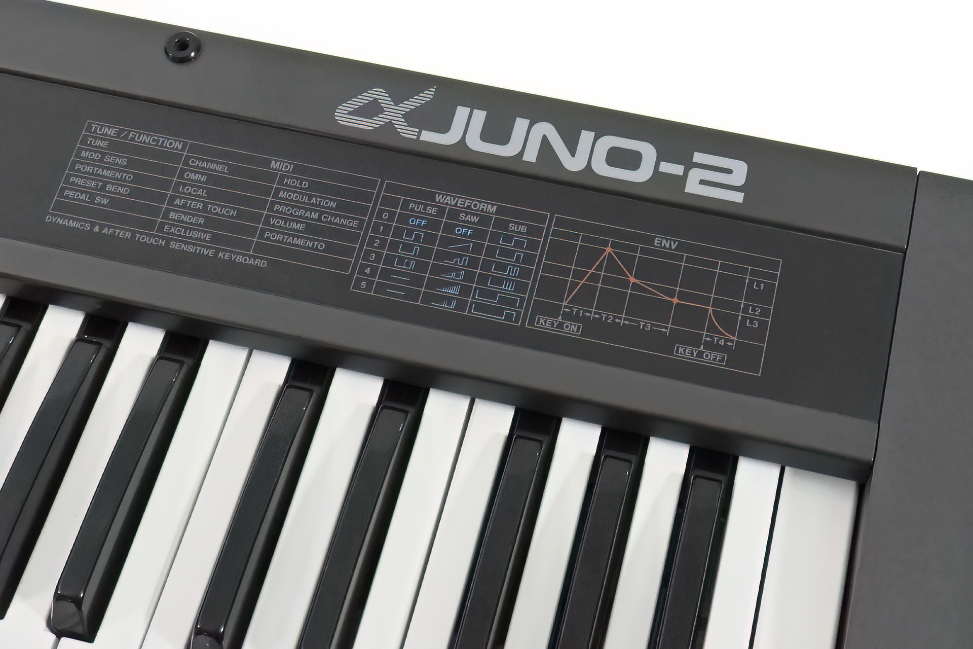
Back in the summer, a customer in Switzerland purchased one of my AT-AJ-2 replacement aftertouch sensors for the Roland Alpha Juno 2. After some conversation, he started talking about a Roland Alpha Juno 2 full service as so many things were wrong with his newly acquired instrument.
With the vast majority of my business coming from outside the UK, it's important to get things right and so advising customers on packaging and even arranging collection via my DHL Express (import) account, ensures that things go smoothly. It doesn't stop there, though. Receiving valuable instruments from far-away places is very humbling as customers trust that their equipment will be treated with care and respect and that items will undergo rigorous inspection and testing prior to being returned to the customer.
Anyway, back to the Roland Alpha Juno 2 full service story... As many might be aware, I had August off, mainly due to my eldest daughter's wedding so the AJ-2 didn't come in until a few weeks ago.
Well, cosmetically, it was in beautiful condition but indeed, there were several issues, many of which were kind of expected, due its age.
The backlight on the LCD was shot, the aftertouch wasn’t working and many keys either didn’t sound, were intermittent or triggered with full velocity. You know what I’m talking about.
On opening her up however, I got a bit of a shock as the condition of the inside wasn't anything like that of the outside. There were obvious signs of fluid damage and the key-bed was absolutely filthy, covered in dust, animal hairs and other contaminants. Remnants of spider's inhabitation were also present. 😕
Most issues were pretty straight-forward to put right but boy, that key-bed needed cleaning, cleaning and then cleaning again.
The customer decided to take advantage of the situation and asked me to change the battery and the chorus chips suffice to say that as opposed to replacing the dead backlight on the original LCD, a new OLED was dropped in and of course, the new aftertouch sensor was installed, changed expressiveness of the instrument completely.
My AT-AJ-2 replacement aftertouch sensor for the Roland Alpha Juno 2 is a perfect fit in all dimensions and is really quite discrete.
Benefitting from a Roland Alpha Juno 2 full service as well as a brand new FSR-based aftertouch sensor and OLED replacement display, this instrument is now not just in great cosmetic condition but works flawlessly!
On a side note, the Roland Alpha Juno 2 is probably one of the company's most underrated synthesisers. It has a gorgeous sound which oozes analogue and I can only imagine that because its not big like a JX-10 for example or even a JX-8P, people kind of don't 'see' it, if you know what I mean. Having said that, a good example will still go for a respectable price.
Of course, this image isn't from 31st July when I launched this post but from 16th October when the PML-TX01 transformers finally arrived.
While I desperately await the arrival of a parcel from Malta, I have decided to put up and maintain this PML-TX01 UPDATES 2025 post for those who bought this item on a pre-order promise and for those who are interested in buying it.
I'm on annual leave during the month of August 2025. Apart from attending my eldest daughter's wedding, I'm just taking some time out to catch up on mostly personal stuff and little R & D so I'm not going anywhere.
There's one exception to my leave however, and that is to ensure that those customers who pre-ordered my PML-TX01 replacement transformer for the Marshall JMP-1, are looked after and that all pre-orders will be sent out as soon as they land.
It's been about a month since I should have received my latest batch of transformers and although not my fault or that of the manufacturer, I feel a sense of responsibility and can only apologise for this unprecedented situation. It's just not happened before and I'm trying my best to resolve it.
LATEST NEWS (31st July 2025)
The transformers are made in the same factory that made the original JMP-1 transformer. TRX Electronics is based in Malta. I've now confirmed that the transformers are being held in UK Customs. Yesterday I sent an email to ParcelForce Customs Processing requesting more information. Of course, I'll keep everyone updated.
Please check in here regularly.
UPDATE - 10th August 2025
No news yet, people. I'm getting annoyed but my hands are tied. I did have an auto response to my email of 31st July just to tell me that someone should get back to me in ten days. Great! Thanks! 😡
UPDATE - 20th August 2025
I've just received an email from ParcelForce confirming receipt of my shipment from TRX Electronics and that all information pertaining to the shipment has been recorded.
Unfortunately, when I look at the tracking information, nothing seems to have changed! 😡
UPDATE - 15th September 2025
Today I had a note dropped through my front door, requesting duty to be paid. I'm not at all sure why I'm being asked for this, so many weeks after the package had entered the UK but I paid the duty anyway. After confirming a delivery date, I received an email from ParcelForce informing me that the transformers will be delivered the day after tomorrow (Wednesday 17th September).
UPDATE - 17th September 2025
After waiting all day for ParcelForce to turn up, at 9:00 in the eveing, I decided to check the tracking. Here's what it's showing...
I know damn well that I paid Customs charges but I checked anyway. Hmm... Yes, of course I did Mr. ParcelForce. The full amount requested, is showing as having been been deducted from my PayPal account on err... Monday! 😡
ParcelForce is one of the worst organisations on the planet.
If it's going to go wrong, guaranteed ParcelForce will be involved.
I'm so sorry people. Not sure where to go from here. I'll try to sort this out tomorrow.
UPDATE - 24th September 2025
Well, after holding on the phone for almost an hour, I did indeed manage to talk to someone at ParcelForce.
I was informed that there was no record of my shipment from 22nd August and it is assumed that it has been returned to the sender (the factory in Malta). The person I spoke with, confirmed that the duty is indeed appearing on the ParcelForce system as having been paid. I questioned this and didn't get a satisfactory answer. I was however, told that it would be refunded if the shipment had been returned. I was also told to "key an eye on email" and to expect a communication from ParcelForce.
UPDATE - 1st October 2025
After two weeks, the duty paid has not been refunded and neither have I received an email.
Sorting out ParcelForce is my problem but no transformers is my customers' problem. I have therefore, informed the factory to expect the return and we have agreed to use a proper courier. In fact, I'll be using my DHL Express account which usually only takes a few days to ship. I'll be arranging collection myself.
Once again, I can only apologise for this mess but I hope you'll all appreciate that it's not of my making.
UPDATE - 11the October 2025
This morning, I received a note through the front door informing me that I have a package but that there is Customs duty to pay. The package will not be delivered until the duty is paid. The Customs duty required is exactly the same amount as that I paid on 15th September (almost a month ago). It's too much of a coincidence and so I'm assuming that the parcel in question is the parcel containing the transformers.
If you've been following my record of this complete and utter fiasco, then you'll be aware that I haven't been credited (as I was promised), the Customs duty that I paid on 15th September. ParcelForce has not realised that while the refence number on the 'redelivery' package is different to that of the original, the two are in fact the same.
Being a Saturday, I will have to wait until Monday before I can telephone. That will be another hour out of my life while I wait on the phone to talk to someone.
UPDATE - 13th October 2025
After waiting on the telephone for one hour and twenty-two minutes, I got to talk to a real person. I was told that the parcel should have been out for automatic delivery today but it is not and that the request for Customs duty note that I received om Saturday, was a mistake. The customer service assistant advised me that the parcel had NOT been returned to the sender, that it had in fact been only returned to the local ParcelForce depot and is now be scheduled for delivery on Wednesday 15th October 2025. WTF?!?!?!?! The conversation took about ten minutes which means that I've spent over one and a half hours on the telephone this morning to get to where I should have been four months ago.
I'm not going to jump up and down with excitement as I don't believe anything that Parcel Force tells me. If the transformers are delivered on Wednesday, I will of course let you know.
Amazingly, after finishing this update, I received an email from ParcelForce, confirming a Wednesday delivery. Hmm....
UPDATE - 15th October 2025
I've been waiting in all day because today is Wednesday and I was told that the package would be delivered today. At 4:30 I checked the tracking and guess what? At 14:58, the package status was changed from 'Awaiting redelivery' to 'Customs duty to pay'.
It's 4:35 and I'm now on the phone waiting to talk to an advisor.
UPDATE - 16th October 2025
So I was told that the parcel would definitely be delivered today. At 10:10 this morning I just thought I'd check the tracking. As you can see, the message displayed tells me that it's being returned to the sender (in Malta). Well, I don't believe that either so right now I'm on the phone again.
Incidentally, the tracking history has completely changed from last last night. The history between 10th October and 15th October has disappeared!
After hanging on the phone for well over an hour, at 11:30 I was told by the customer services advisor that the case has now been escalated to the management. Big deal! 😡
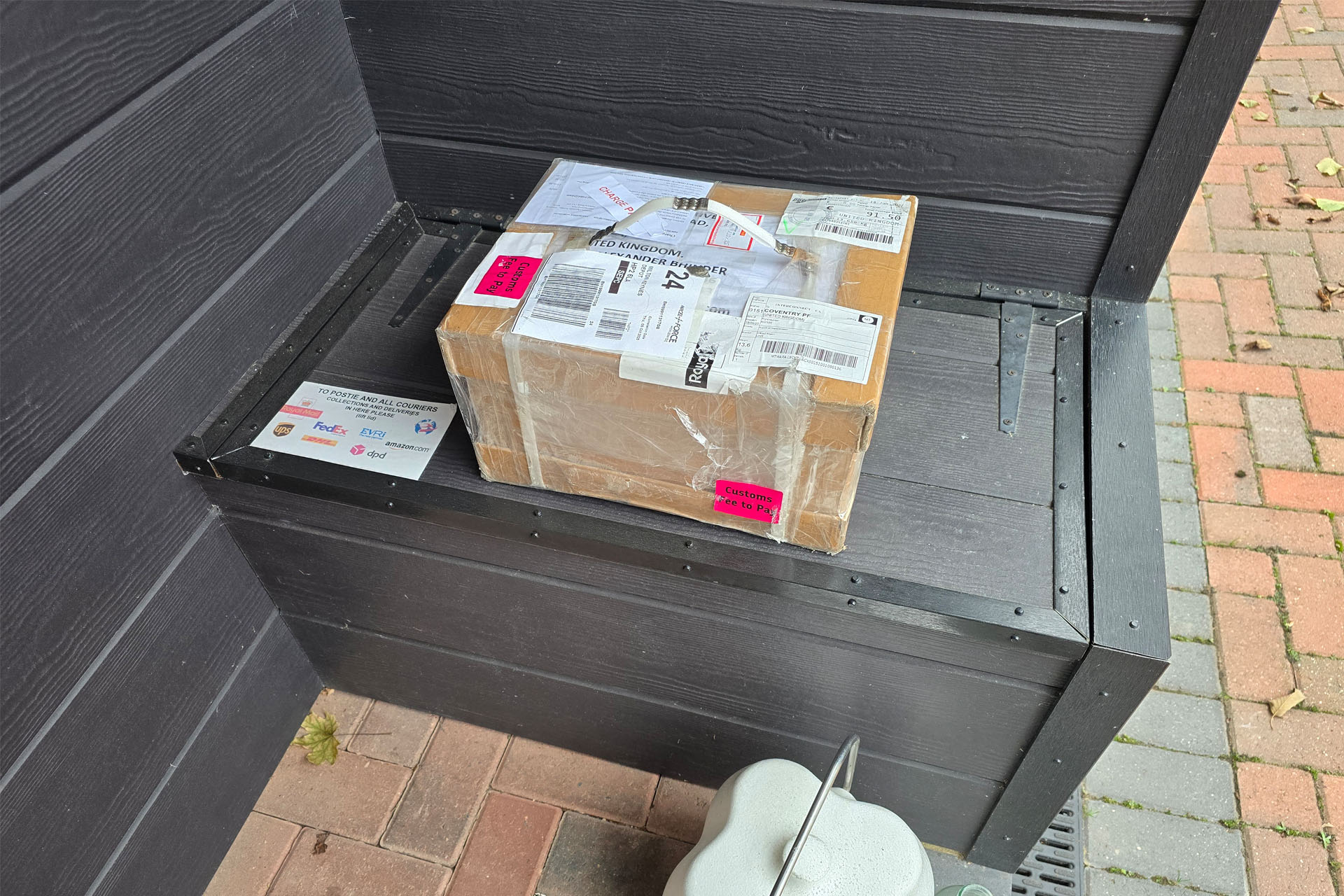
It's now 4:00 and PML-TX01 UPDATES 2025 is delighted to report that the transformers were delivered about twenty-five minutes ago!
I don't know what to say other than a lot of these will be going out early next week to all the good people who backordered. It looks like I'm going to have a busy weekend. Once again...
THANK YOU again for all your patience. ❤️
I received a notice of shipping from the factory on 23rd June. It's taken almost four months for the transformers to get here and 90% of that time, the package has been sitting in a warehouse in Milton Keynes, about 40 miles (65km) away.
The waiting, the phone calls, the misinformation, the crap tracking and the stress have all been off the scale but I'm so happy that the transformers are finally here.
As has been previously mentioned, I'll be taking measures to ensure that this doesn't happen again.
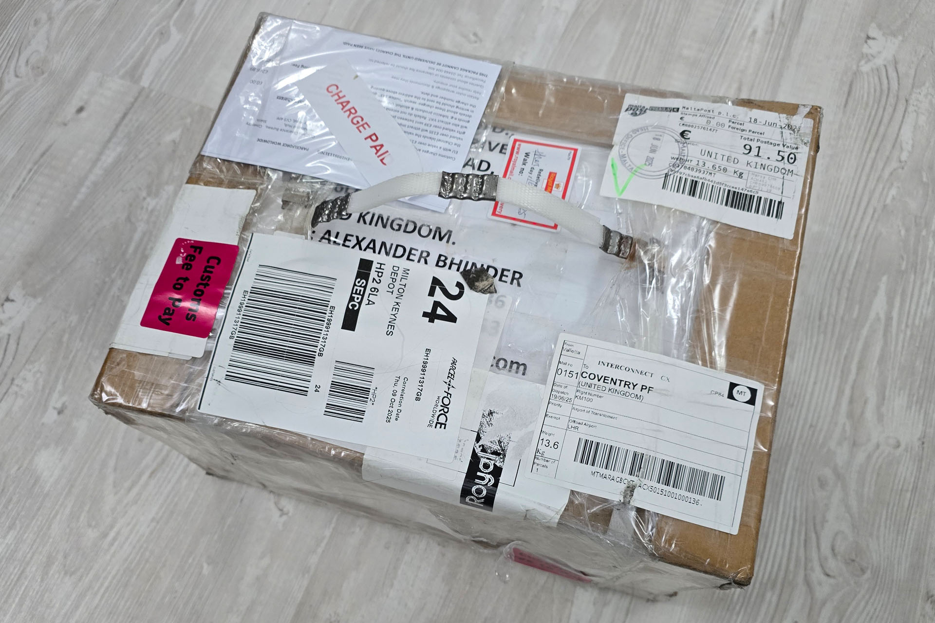
My final update for my post, PML-TX01 Updates 2025. I can't believe that this has finally arrived. Check out the amount of stuff that's been stuck on this parcel. No wonder no one knew what was going on!
It was my wife's birthday on 22nd May and a couple of weeks prior, I decided to buy her tickets for Duran Duran. I actually bought four tickets, two for our friends Belinda and Andy.
Today is 6th July. It's stupid O' Clock in the morning and we've all just got back to Hemel Hempstead from a fantastic day out.
Duran Duran were playing at Great Leighs in Essex, very close to where Julie used to live and where I also lived for a while.
The best of company, Nile Rogers supporting and of course, Duran Duran, a real blast from the past for me both professionally and personally made yesterday really special.
Girls on Film!!!!
I even bumped into Adrian, one of my (Simmons) customers and later, our long time friends Sarah and Neil who used to live opposite us like a million years ago and who now live in Scotland.
Old neighbours Neil and Sarah. How lovely to see you guys again!
One thing about being in music production though, is that you sometimes need to switch off, forget the detail that you would listen to in the studio and just lose yourself in the vibe. When things got serious for me, the slightly high mix of Alex Van Halen's hi-hat for example, really started to get on my nerves. Seeing one of my favourite bands of all time live, required that I kind of had to train myself to let my emotions take over and to leave my studio ears in well, the studio!
Another example is George Lynch, who's sound and technique were a big influence on me but many years ago, I went through a phase when I found it hard not hear the badly mixed lead guitar overdubs.
The energy that Duran Duran projected into the crowd was amazing but I have to say that the overall sound wasn't at all great. Nile Rogers' mix was so much better. Duran Duran's sound was messy and inarticulate and I must admit to being deeply disappointed with Tom Brown's guitar sound and playing. He had way too much distortion (as opposed to overdrive) when he should have and some riffs like the unmistakable Rio, simply weren't played properly, with the signature 'slide' not being present. How come none of the other guys spotted that in rehearsals?
Of course, Belinda, Julie and Andy were quite oblivious to any of that and the girls in particular simply danced the night away. I eventually got sucked in and just enjoyed myself. 😎
Last year I developed several peripherals for the Simmons SDS7 and it would seem that they're now becoming quite popular. Here are four 2025 Simmons SDS7 upgrades that I’ve had in recently.
Here's the upgrades that have been installed into these units:
A – Dark Matter switched-mode power supply installed. Pleiades lithium battery conversion and discrete MIDI platform installed. NC-7 noise-cancelling mod installed.
B – Dark Matter switched-mode power supply installed.
C – 120V – 240V conversion. Pleiades lithium battery conversion and discrete MIDI platform with Tubbutec uniPulse installed. RESET-7 Power-on-Reset upgrade installed.
D - Dark Matter switched-mode power supply installed. Pleiades lithium battery conversion and MIDI platform with Tubbutec uniPulse installed. Repair of bass drum module.
E - All customers have also purchased AMEP Advanced Memory Expansion Pack.
I've used the adjective 'discrete' to describe the MIDI platform feature of Pleiades. That's because all of my upgrades are designed around three main objectives:
The outside of the equipment should remain untouched.
The inside of the equipment should require no permanent alteration.
Any upgrade can be easily removed and the equipment can be returned to factory.
Working to those three objectives can be quite challenging but hey, that's what I do! 🙂
Okay so you all know that I really love my job but the four Simmons SDS7 upgrades I've done so far this year have been a particular delight to work on, great fun and most rewarding. It gives me a true sense of comfort and pleasure to know that these iconic instruments will be banging away for another forty years!
A lot of the early Simmons stuff, can be, well... rather interesting to work on but nothing is quite as quirky as the SDS7. With a personality which can only be described as unpredictable, you really need to know what you're doing and in particular, you kind of need a lot of patience. Yes, it's only classic early eighties electronics and yes, that should sound easy but nothing ever goes quite according to plan when working on a Simmons SDS7!
The 120V to 240V conversion of SDS7 'C' in the image above, should have been really quite straight-forward but for the first time ever, I had a duff transformer. I couldn't believe it but the 240V tap was open circuit. This fault must have existed since production.
Destined to be for the US market, there's no way the that the transformer's 240V tap would have been tested at the Simmons factory or during the SDS7's past forty year life in the US. Luckily, due to the Dark Matter upgrades I've done over the past few months, I've built up a small stock of spare transformers.
Between common and the 240V tap, this Simmons SDS7 mains transformer should read about 38Ω. As you can see, this is definitely not the case.
WANT TO FIND OUT MORE? Here are links to posts featuring the products mentioned above:
All items are available for purchase in the Simmons SDS7 Heaven category in my online store. If you're unable to install stuff yourself, then as you can see, I'm always happy to take in your SDS7 and do the work for you. Just contact me for a chat.
Four Simmons SDS7 upgrades so far this year and it's only June. Wow!
UPDATE - 7th April 2026
Joining the above upgrades that I offer for the Simmons SDS7, is Gary 7 MIDI kit selector. You can read all about Gary 7 here.