

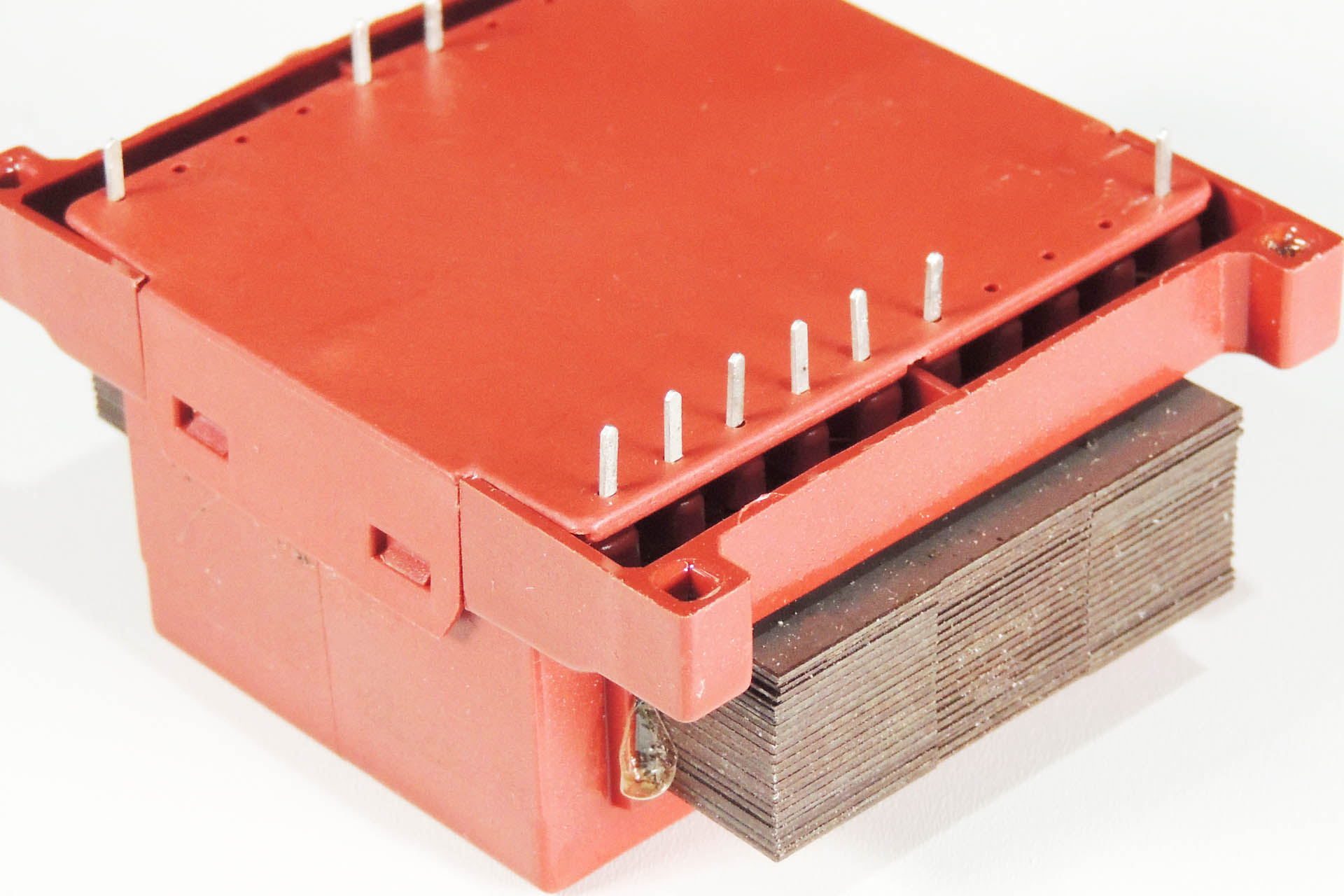
Many users of this well known pre-amp, will be familiar with the infamous Marshall JMP-1 hum! Emanating from the transformer, the hum is caused by oscillating laminates which don't just produce hum but also can generate a huge amount of heat, thereby potentially reducing the life expectancy of your transformer.
Months in the making, I'm delighted to announce my new PML-TX01 replacement transformer for the Marshall JMP-1.

Looking just like the original TXMA-00014 and being pin-for-pin compatible, my PML-TX01 is identical except for one feature; the material used for the laminates is of a much higher quality. This single unique aspect of the PML-TX01 reduces the likelihood of laminate oscillations, excessive heat and mechanical hum.
In a quiet recording environment, the Marshall JMP-1 hum is super-annoying and at last, a solution is now available. If you have hum issues with your JMP-1, then I strongly suggest that you consider this little upgrade.
This item regularly goes out of stock, I'm afraid but... I encourage customers to back-order. Unfortunately, the crappy e-commerce plug-in I use, only tells the links (like the one above) that the item is out of stock. What 's the bloody point of that?!?!?! So if you want this, then please just visit the PML-TX01 page on my e-store here.
MARSHALL JMP-1 VOLTAGE SELECTION
I regularly receive two questions from those interested in my PML-TX01:
- Is the PML-TX01 replacement transformer for the Marshall JMP-1, 240V or 120V?
- Are the voltage selector components diodes, ferrite beads or just fancy wire links?
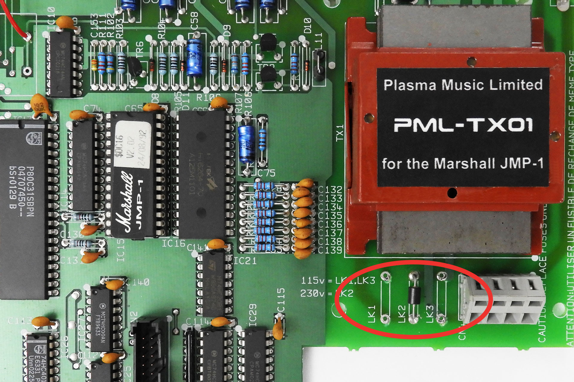
The answer to the first question is, just like the original TXMA-00014, my PML-TX01 has two separate primary windings, each rated at 115V. So…
- EUOPEAN / UK VOLTAGE SELECTION. Wired in series, the primary becomes a single 230V winding which is suitable for 220V (Europe) and 240V (UK, Australia). To wire in series, connect ONLY LK2.
- USA / CANADA / JAPAN VOLTAGE SELECTION. Wired in parallel, the primary becomes a single 115V winding suitable for 120V (USA and Canada), 100V (Japan). To wire in parallel, connect LK1 and LK3.
It's quite easy to implement 240V to 120V conversion, or 120V to 240V, for example. Those eighties style wire links can make things look complicated but the original links were JUST WIRE LINKS and nothing else, so you can use wire.

It's important that the input voltage selection is chosen properly so below things are drawn that may be more representative of what you might actual see in your JMP-1.

SIDE NOTE
One might ask why the two individual primary windings are put in parallel for 115V. Why not just use one winding?
Well, a system uses a certain amount of power. Power is the product of voltage and current: P = V x I.
You can probably see now that if you half the voltage, you'll need twice the current to deliver the same amount of power. Placing the two primaries in parallel does just that, it doubles the current going into the system. 🙂
And lastly...
! ! ! DON'T FORGET TO CHECK THE FUSE RATING ! ! !
So as I've just intermated, the power requirement of a machine is the same whatever the supply voltage. Since power = current x voltage, if you're halving the voltage, you'll be doubling the current.
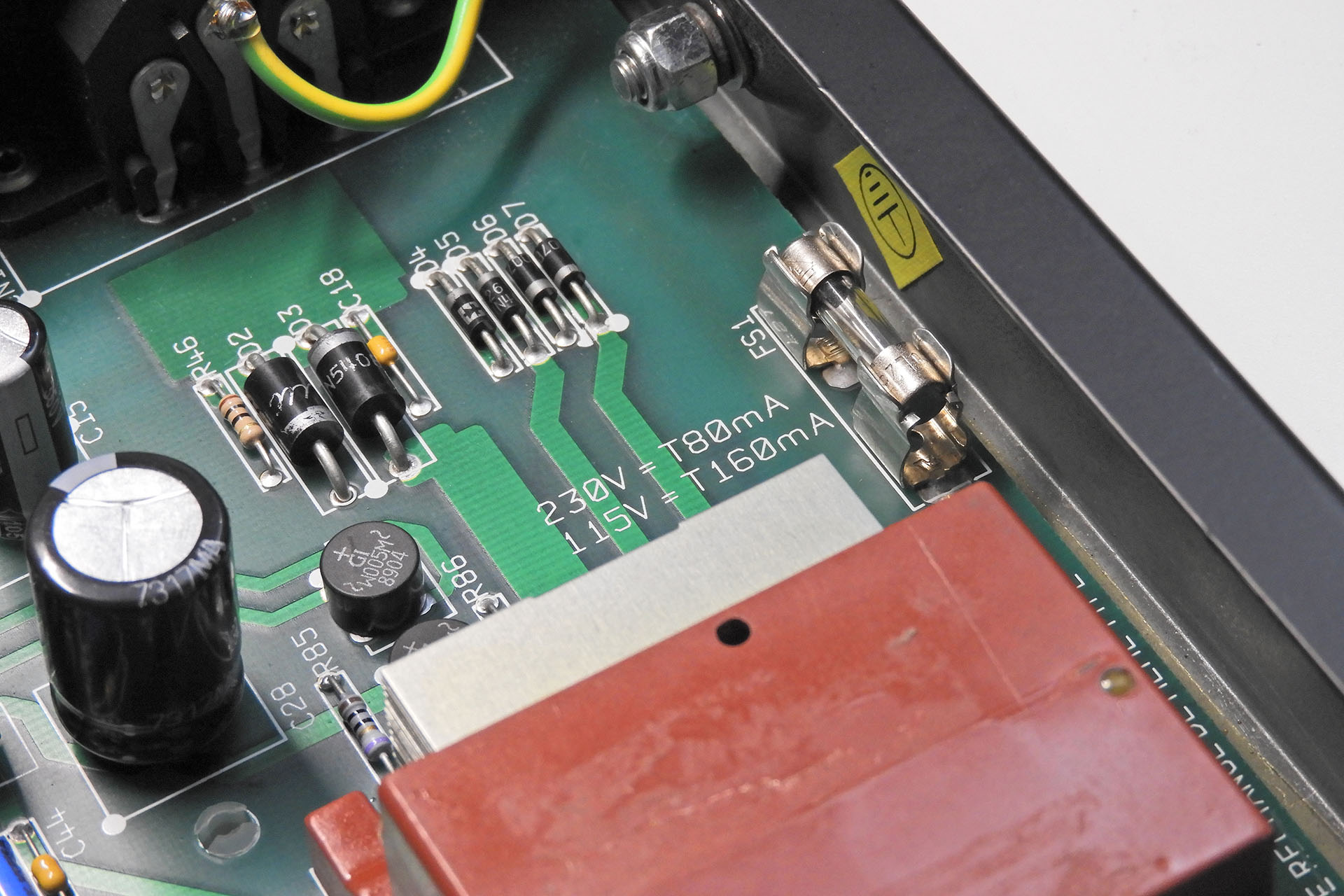
If running at 230V, the JMP-1 fuse should be 80mA (230V x 0.08A = 18.4W).
If running at 115V, the JMP-1 fuse should be 160mA (115V x 0.16A = 18.4W).
'T' stands for 'time delay' so use a time delay fuse.