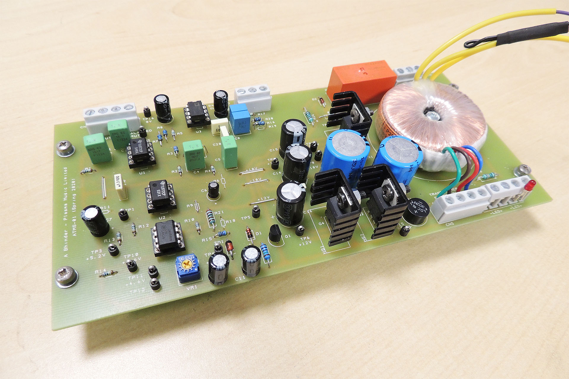
Over the past couple of weeks, I’ve been designing an audio triggered power switch; a gadget to switch on a power amp when an audio signal is detected and to wait a few minutes to switch off the power amp when no signal is present on the input.
The audio signal comes straight from the sub bass output of an A/V receiver amp and is therefore about -10dBV (approximately 310 mV) unbalanced. So apart from auto switch-on / switch-off, the circuit also amplifies the input signal to +4dBu (about 1.25 V) balanced which is whet the power amp wants to see on its inputs.
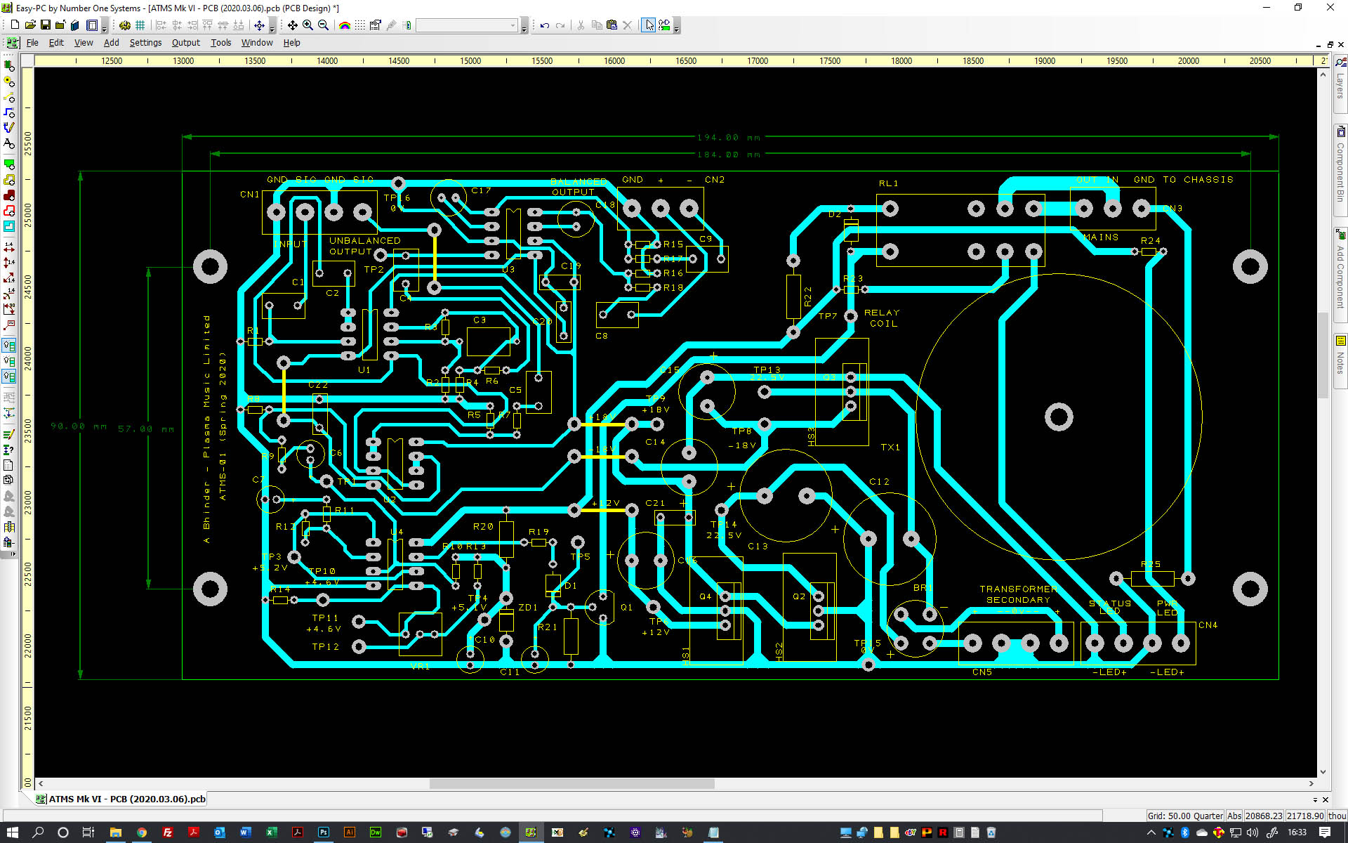
After testing a prototype for several months, this evening I ordered the PCB (the design of which is pictured above) for the final version.
SO WHAT'S THIS ACTUALLY USED FOR?
Well, the power amp in question, drives a sub-bass system on a home cinema. It's a big, professional amp and definitely wouldn't come with auto power-on / power-off or standby, which of course, the main (consumer) A/V receiver amp does have and which 99.9% of consumer sub-bass units have built-in.
The idea is that when the home cinema system is switched on, the power amp comes on when it detects a signal. When the system is switched off, the power amp switches off a few minutes later... PERFECT!
I wanted a minimal signal path for the audio that's being sent from the A/V receiver to the power amp, with just a little gain (-10dBm to +4dBm) and unbalanced to balanced conversion and I also wanted bags of headroom so the whole thing runs at +/-15V.
CREDITS
I don't see the point of reinventing the wheel, especially if someone has already designed something really good that works. Hence, the switching circuitry of this gadget is based on a design by Rod Elliot of Elliot Sound Products (see project 38). Rod puts up some fantastic, in-depth explanation into how the circuit works and how it can be tweaked to your specific requirements.
UPDATE - 18th February 2020

This morning, my PCBs arrived. I couldn't wait and quickly got down to populating one of them ready to test later in the afternoon.
Well, I'm pleased to report that all worked well. With a 1kHz sine wave, the sensitivity of the circuit is about 4.5mV and the delay to switch-off time is about ten minutes.
Unfortunately, the case I'll be using for this, is currently out of stock 'till 17th March, so it looks like this is going to sit on the shelf for a few weeks 🙁
UPDATE - 18th March 2020
Today I went over to RS Components in Watford to collect the enclosure that I'd planned to use for this project and the dimensions of which were part of the design of the PCB. Well, I couldn't believe what I was told; the boxes remain on back-order 'till, wait for it... 31st July. Seriously?!?!? I checked last night and there was no change in status. What the hell are you playing at?

