

Never thought I’d make a new friend over lock-down but I have recently struck up a relationship with Guy Wilkinson of supersynthprojects.com.
While working on a very broken Roland MKS-70 that I have in for repair, I came up with the idea to design a MKS-70 power supply replacement but figured that after all these years, perhaps someone has already thought of this. After a few minutes of searching on-line, I stumbled across https://supersynthprojects.com. The work that Guy has done, is truly amazing. His power supply design is quite simply, elegant and I’m so impressed with his methodical record keeping. As it turns out, Guy seems to be a bit of an expert on several vintage machines.
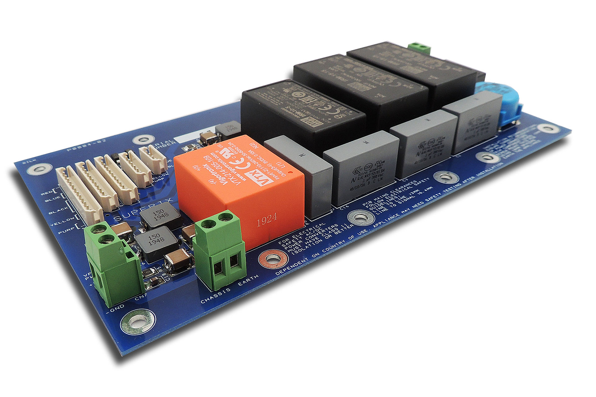
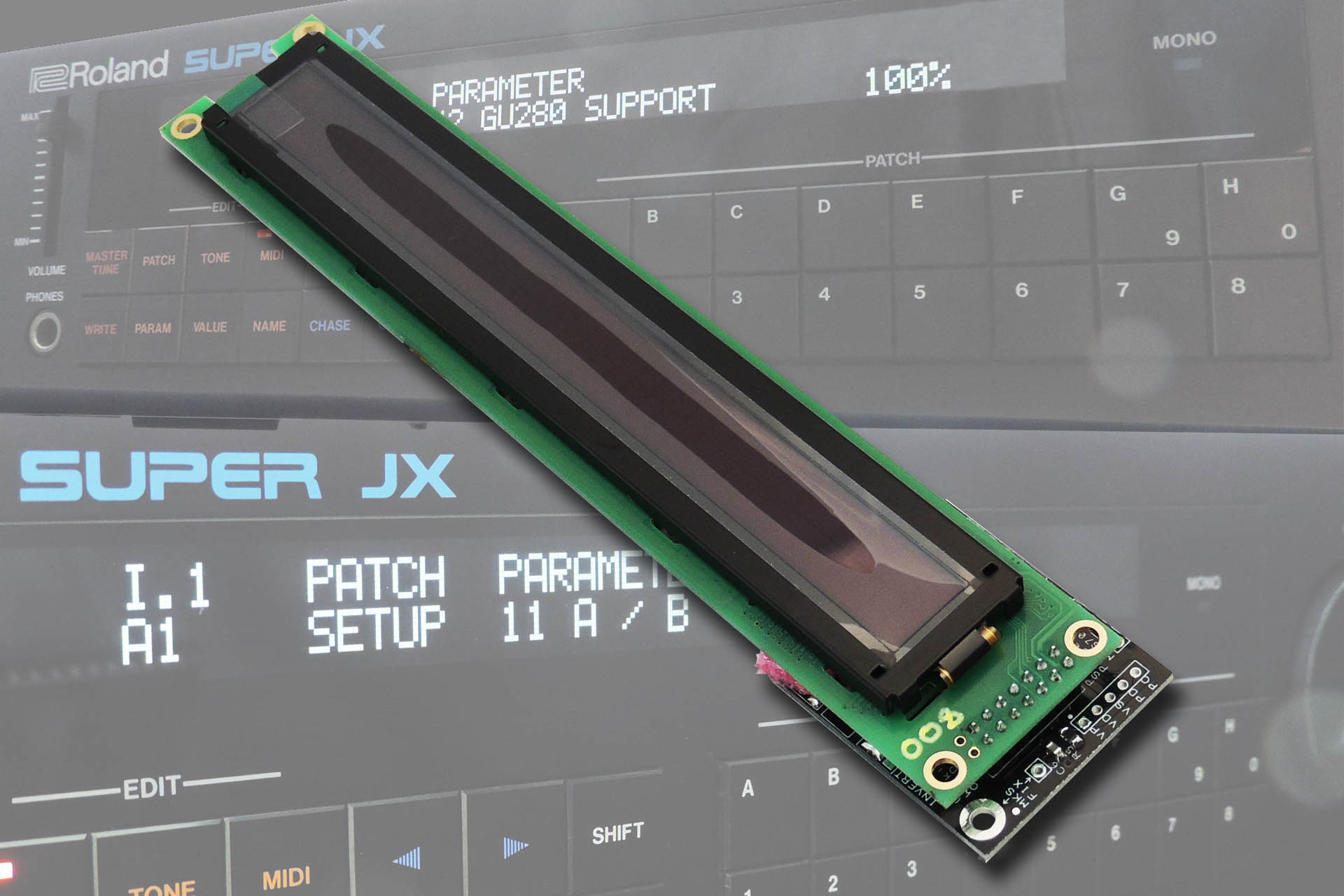
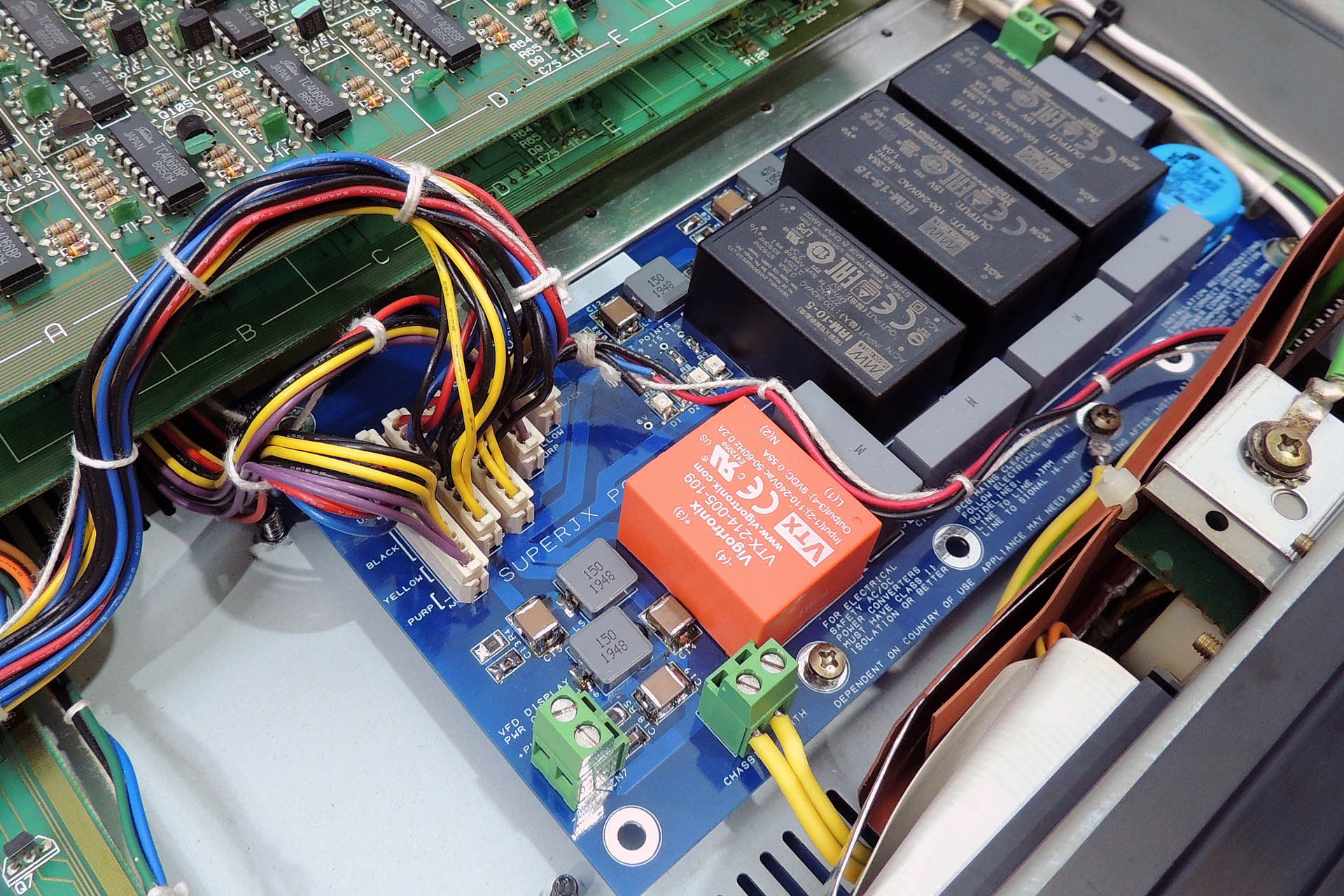
Anyway, having a Roland MKS-70 myself, one thing led to another and I’m currently in the process of building one of Guy’s P0004 switched-mode power supplies and installing his Super-JX OLED display module into my own MKS-70. It’s a bit difficult doing this during lock-down but I’ll keep you posted of progress.
Guy sells the P0004 switched-mode power supply bare PCB and the pre-assembled Super-JX OLED display directly but you'll need some competence to populate the former and fit either, into a JX-10 or MKS-70. If you're cool enough to admit that all of that sounds a bit too much for you, then please don't hesitate to contact me to discuss getting either (or both) fitted into your machine.
Click here for prices.
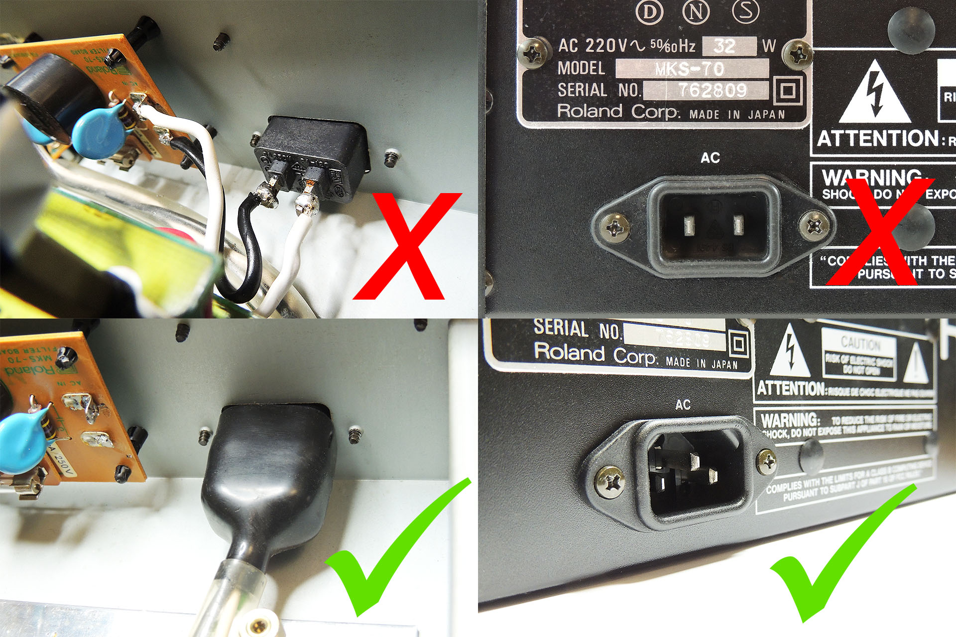
If you're fitting the switched-mode power supply module yourself and your MKS-70 or JX-10 has a 2-pin IEC mains input socket, then you must replace it with a 3-pin IEC mains input socket. The replacement switched-mode power supply MUST be connected to earth as must the chassis of your Super-JX.
I offer a comprehensive earth bonding kit comprising the following:
-
- 1 x IEC 3-pin chassis socket.
- 1 x insulating boot for IEC socket.
- 2 x Pre-cut earth leads terminated at one with earth tag.*
- 1 x M3 earth tag (for one side of IEC socket).
*One earth lead connects IEC earth to chassis via one of the screws that secures the IEC socket. The other earth lead connects the P0004 power supply to the chassis via any M3 screw.
FOR YOUR INFORMATION
The IEC C14 socket that I use, is a drop-in replacement for the 2-pin IEC connector found on many Roland keyboards and rack modules. It is NOT necessary to drill, file, cut or modify the case to fit this IEC C14 socket.
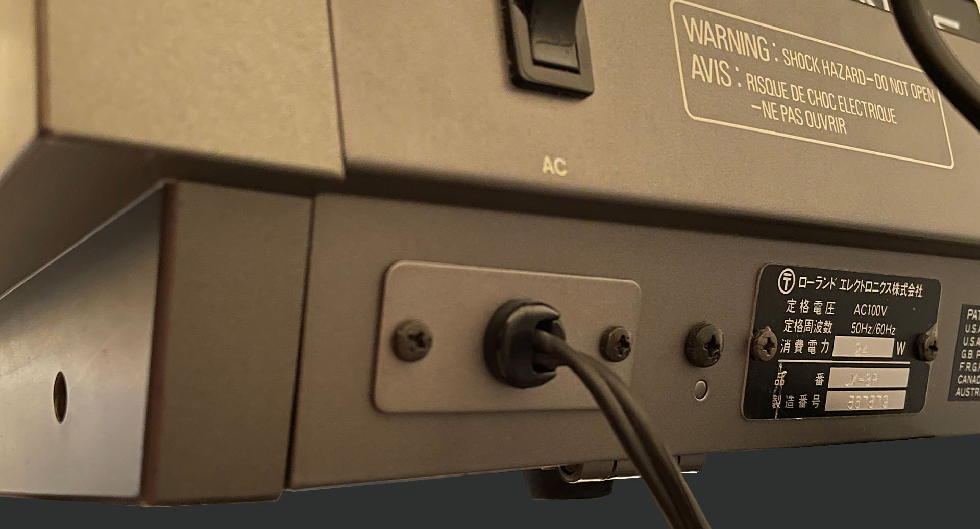
A little known fact is that even keyboards with integral (hard-wired) power cables, have the power cable mounted to a metal bracket which is secured to the same screws holes and with the same type of screws, that are used on versions with IEC connectors! Behind that plate, is a cut-out for an IEC C14 connector.
Below is an image of the back of a Japanese JX-8P with a hard-wired power cable. You can clearly see that the cable goes into a cable gland which is in a very IEC C14 sized metal plate. T H A N K Y O U, Roland!!!!
UPDATE - 10th MAY 2020
Last night I installed the assembled switched-mode power supply into my own Roland MKS-70. I'd already tested it outside the machine but I was still nervous. Hey, the MKS-70 fired up straight-away. The power supply worked just fine and quite honestly, if you're having issues with the power supply in your Roland MKS-70 or JX-10, then getting one of these is a no-brainer!
UPDATE - 12th MAY 2020
Took a while and was a bit tricky but the display got done and works absolutely brilliantly (pardon the pun). In fact it looks positively beautiful.
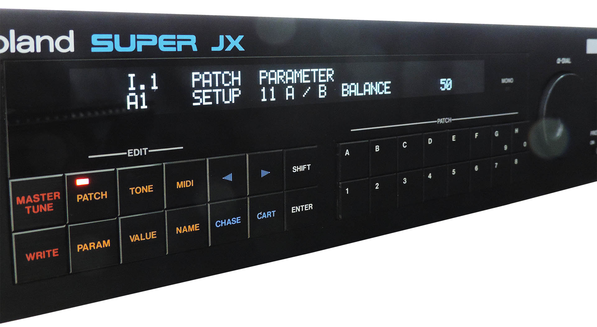
The Super-JX OLED module 'learns' the system's firmware so before I switched on the unit to test, I thought I'd drop in the Vecoven Super-JX flash module. Pressed the power button and everything powered up just great.
UPDATE - 19th MAY 2020
Several days ago, I posted here that I'd keep you updated of progress on this project. I also suggested that I'd probably end up making a new post. Guess what? So, click here for more on Roland Super-JX Upgrades.
UPDATE - 9th June 2022
I'm a big believer in the saying "If it ain't broke, don't fix it". On the other hand, isn't wisdom all about taking action before stuff goes wrong?
Today I had the most terrible job of telling a customer that the only way he's going to get his MKS-70 up 'n' running, is by acquiring a new assigner board. 🙁 That basically means buying a new MKS-70!
Yet another PSU failure and yet another totally scrapped MKS-70.
I can't emphasise this enough;
GET A P0004 POWER SUPPLY BEFORE IT'S TOO LATE!!!
Look, there are two MASSIVE hidden bonuses when using something like Guy's P0004 power supply;
- Unlike the original Roland PSU, the +5V supply on the P0004, is NOT derived from the +15V line and is fully independent. Hence, any fault on the +15V line, won’t affect the +5V supply.
- In the event of a failure, the respective supply will simply stop working and chuck out 0V.
Big deal, so... Well, sadly, I occasionally see a MKS-70 which has had a failure of the +5V supply. If the failure is as a result of the +15V going wacky, this often results in the +15V line jumping to like +22V, thus maxing out the +5V regulator circuitry and taking out your assigner board. That’s basically a bricked MKS-70! 🙁