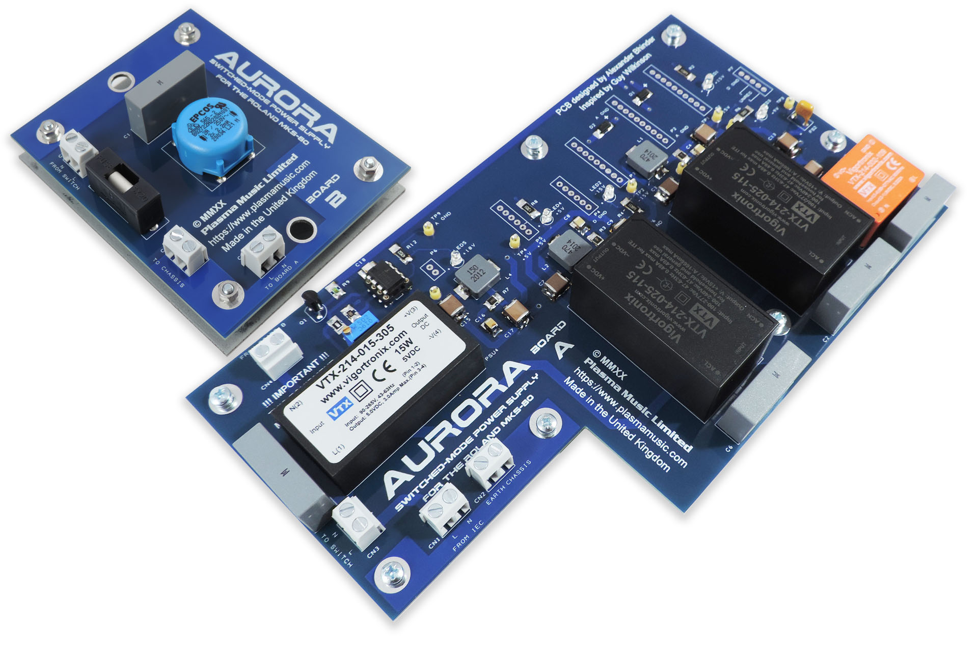
The Roland MKS-80 is an amazing piece of equipment and a lovely sounding machine. As one of the last all-analogue-voiced synthesisers, I am hopeful that Aurora, a replacement power supply for the Roland MKS-80 will keep all of those gorgeous modules still left on the planet, working just a little longer.
Anyone who has a Roland MKS-80 with a power transformer that’s not native to their region, now has the option to upgrade the power supply in their machine and plug it straight into their mains supply, without the need of going through an external transformer.
If your Roland MKS-80 has a bad power supply or broken transformer, you now have the option to potentially bring it back to life. Also bear in mind that the old FR2 PCBs are now very brittle and prone to dry joints and even cracking.
At the time of writing, some Roland MKS-80s have been operating for thirty-six years! While designed extremely well, the power supplies are stressed systems (as in any machine) and the last thing any MKS-80 owner wants is for the power supply in their machine to go south. IC1 on the original PSU for example, is a M5218L. It's a crucial part of the +5V supply and the 10V reference circuit. If this packs up, the +5V rail could rise to values that could seriously damage your MKS-80 and even make it unrepairable. As time goes on, the likelihood of this happening, only increases. The +/-15V supplies which drive the voice boards, are a little more robustly designed.
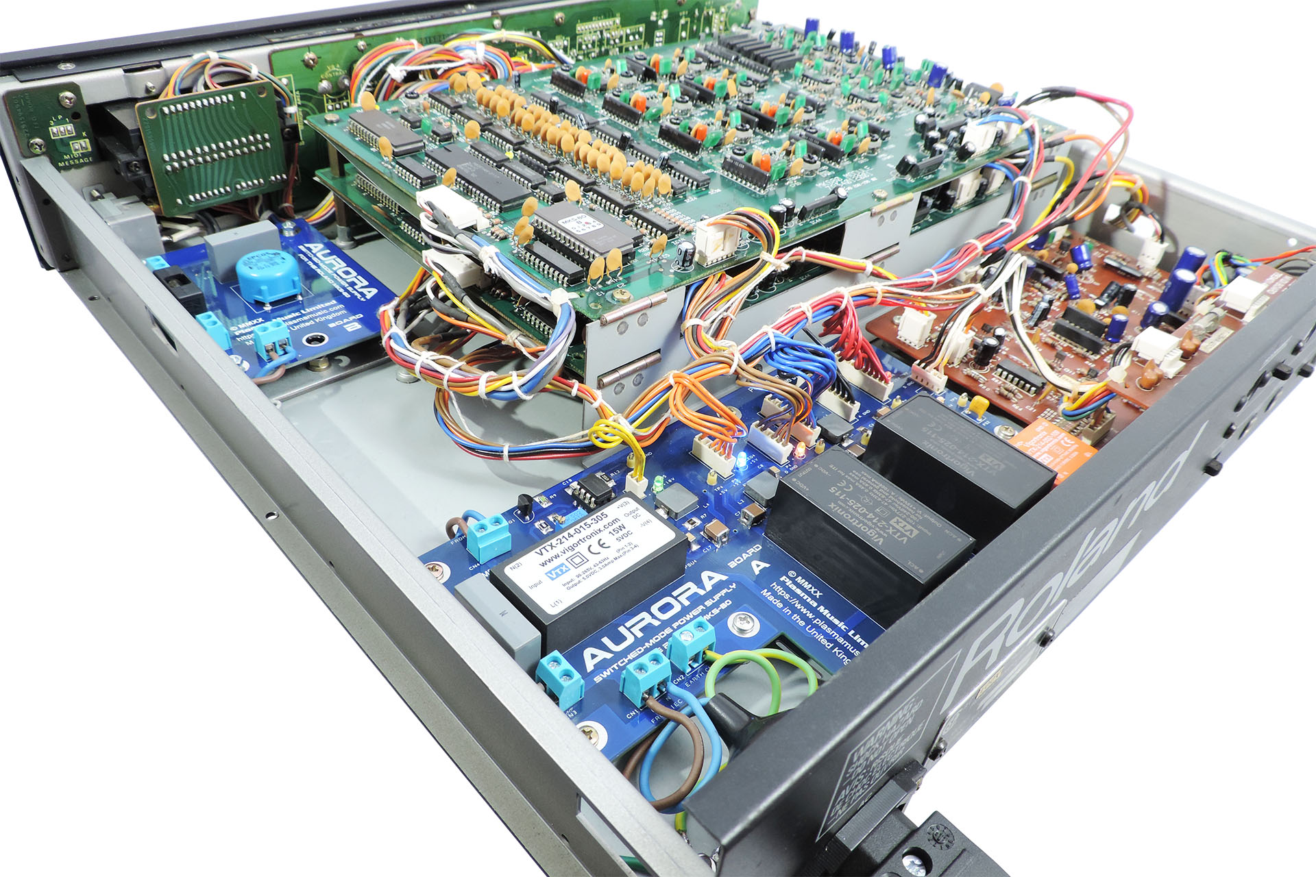
Electronics in general doesn’t like heat. Aurora runs much cooler than the equivalent linear power supply.
Over time, your MKS-80 may develop transformer born hum. This can't be 'filtered' out and you're kinda stuck unless you can acquire a replacement transformer. Hey, you're in luck 'cos Aurora doesn't produce any hum!
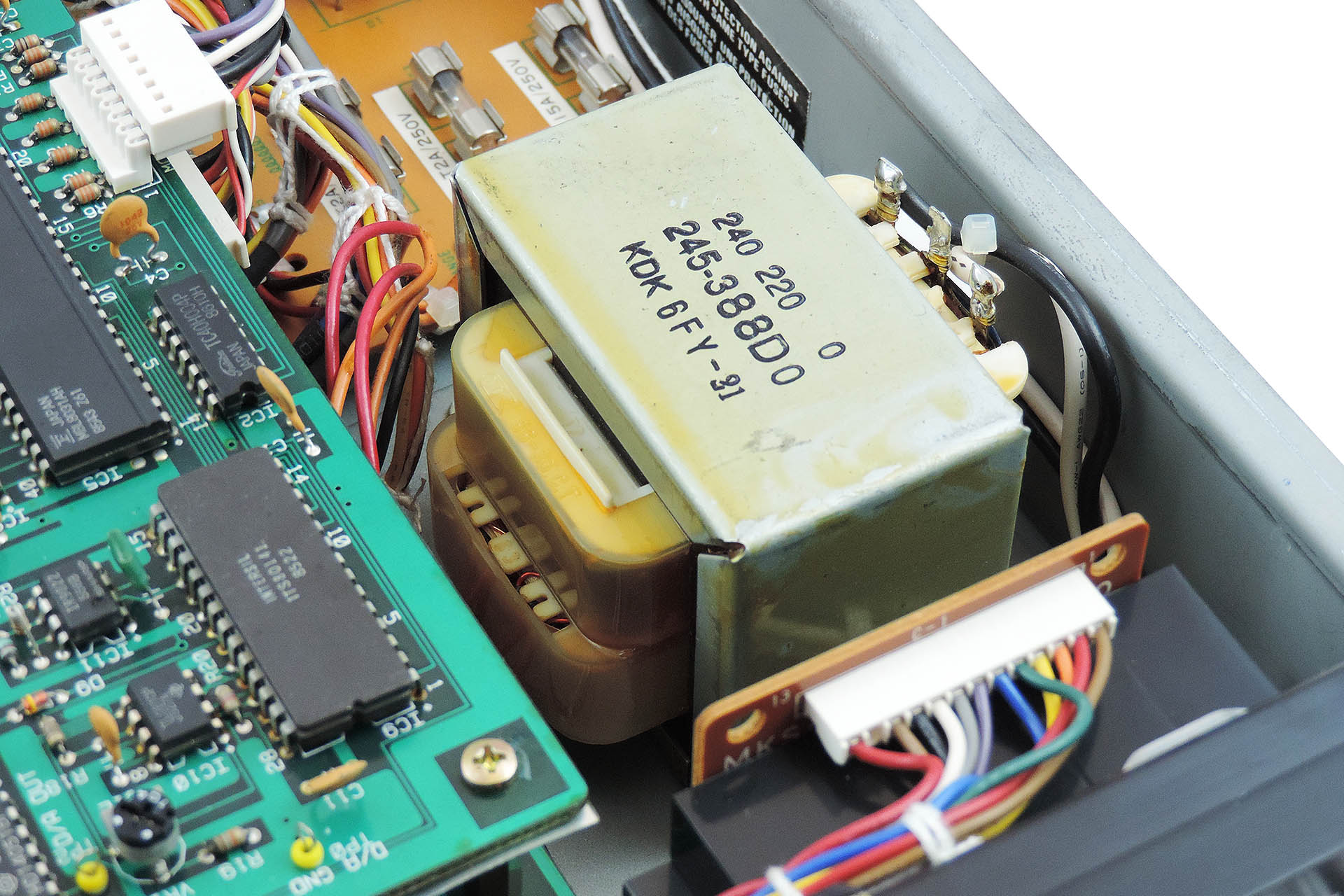
Originally, Aurora was going to copy the footprint of the original MKS-80 power supply. A single L-shaped board however, would have meant a lot of wastage and potentially necessitate the removal of the front panel to replace the original mains wiring which would have been too short to reach the single PCB.
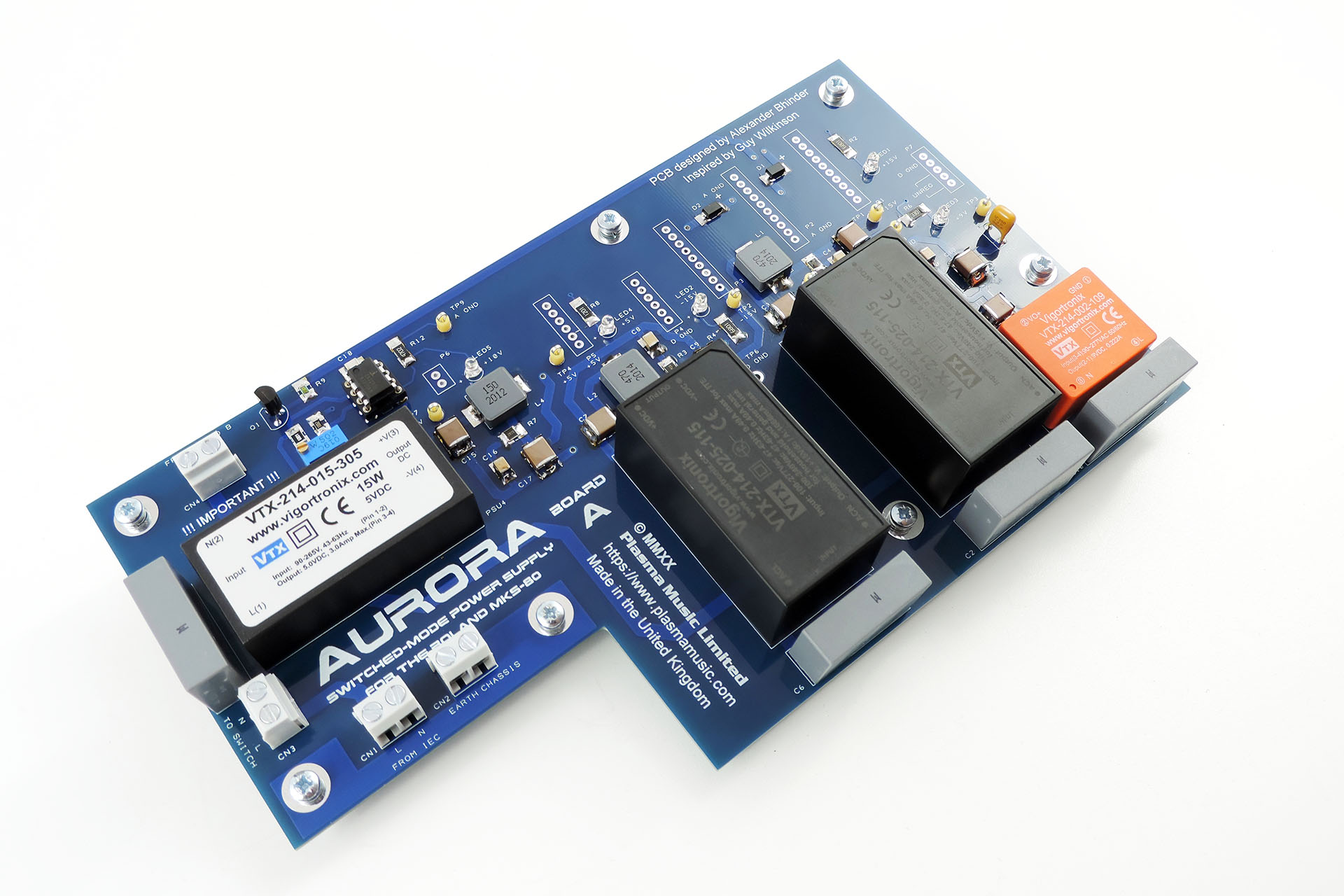
The solution was to split Aurora into two PCBs; Board A being the main part of the power supply and Board B taking care of mains protection and filtering.
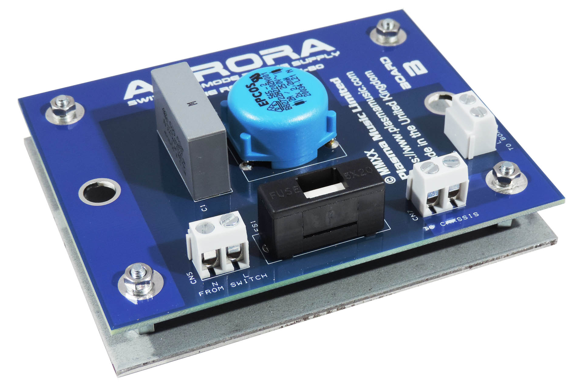
I made use of the reinforcing plate that's underneath the original transformer. The size of board B is the same size as this plate. I simply added four M3 mounting holes and christened it V01, LOL. Whatever, this all provides for a very tidy and cost-effective solution that requires minimal reworking of existing wires, etc.
Aurora's 10V reference source started out as a precision circuit using tight tolerance components and a high-grade op-amp. The results were impressive but later, I changed the design and incorporated a multi-turn trimmer so as to allow for adjustment of the reference which may result from component drift over time.
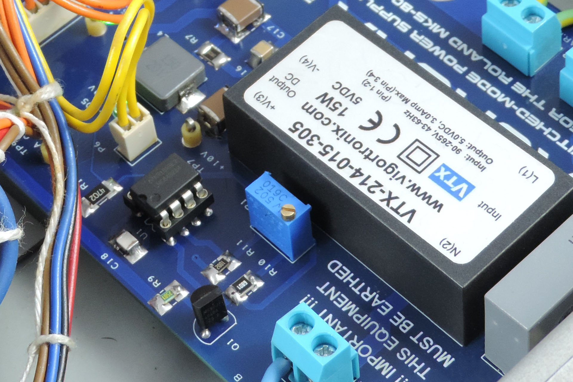
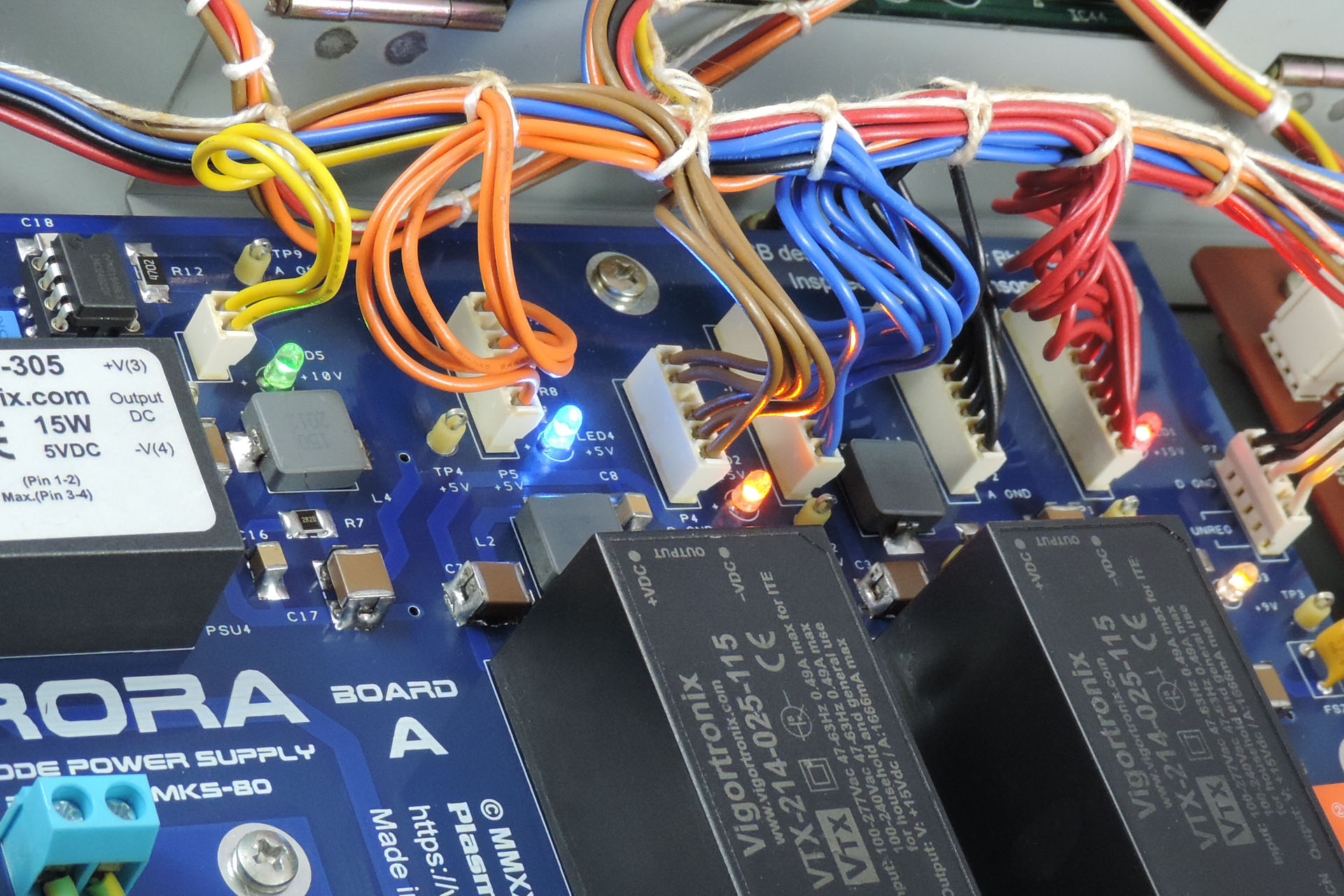
Each supply has it's own status LED. I thought this would be a nice addition and in keeping with the original design although unlike the original, Aurora has a different coloured LED for each supply, including the 10V reference.
Also note the test points allowing for easy checking of all voltages.
So I was going to teach myself Arabic or Mandarin during lock-down 2020 but instead, I kind of decided to design this. It just seemed like a really cool thing to do! 😀 😎
You can read about the development of Aurora Replacement Power Supply for the Roland MKS-80 here.
INSTALLING AURORA
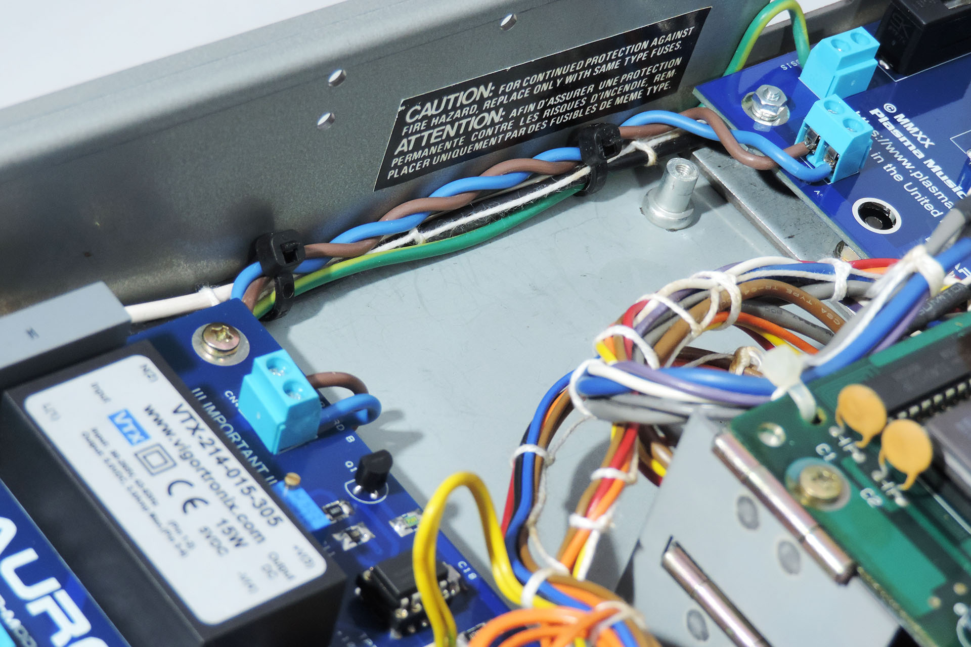
Installing the Aurora boards requires a certain degree of knowledge, experience and skill. I therefore insist that the installation be performed by a suitably qualified technician. Aurora is a power supply that converts mains voltage to several DC voltages that your machine requires. Safety is paramount and although fully tested prior to shipping, I strongly recommend that you test Aurora outside of your machine prior to installation. Since there is mains voltage on both boards, care should be taken that the boards are lifted clear of any work surface during such testing, using for example, PCB stand-offs (spacers).
Removing the original power supply including the transformer also requires a certain degree of knowledge, experience and skill. Remember that these machines are over thirty years to over thirty-five years old.
The voltage distribution headers for example, are soldered to the board. The pins on the headers are not conventional straight pins. They're arrowheads and have a tight fit. Once you're confident that you've removed all of the solder, gently prize them off the board (GENTLY). I suggest that you wiggle the connector from the component side while observing the underneath so as to ensure that all pins are indeed free.
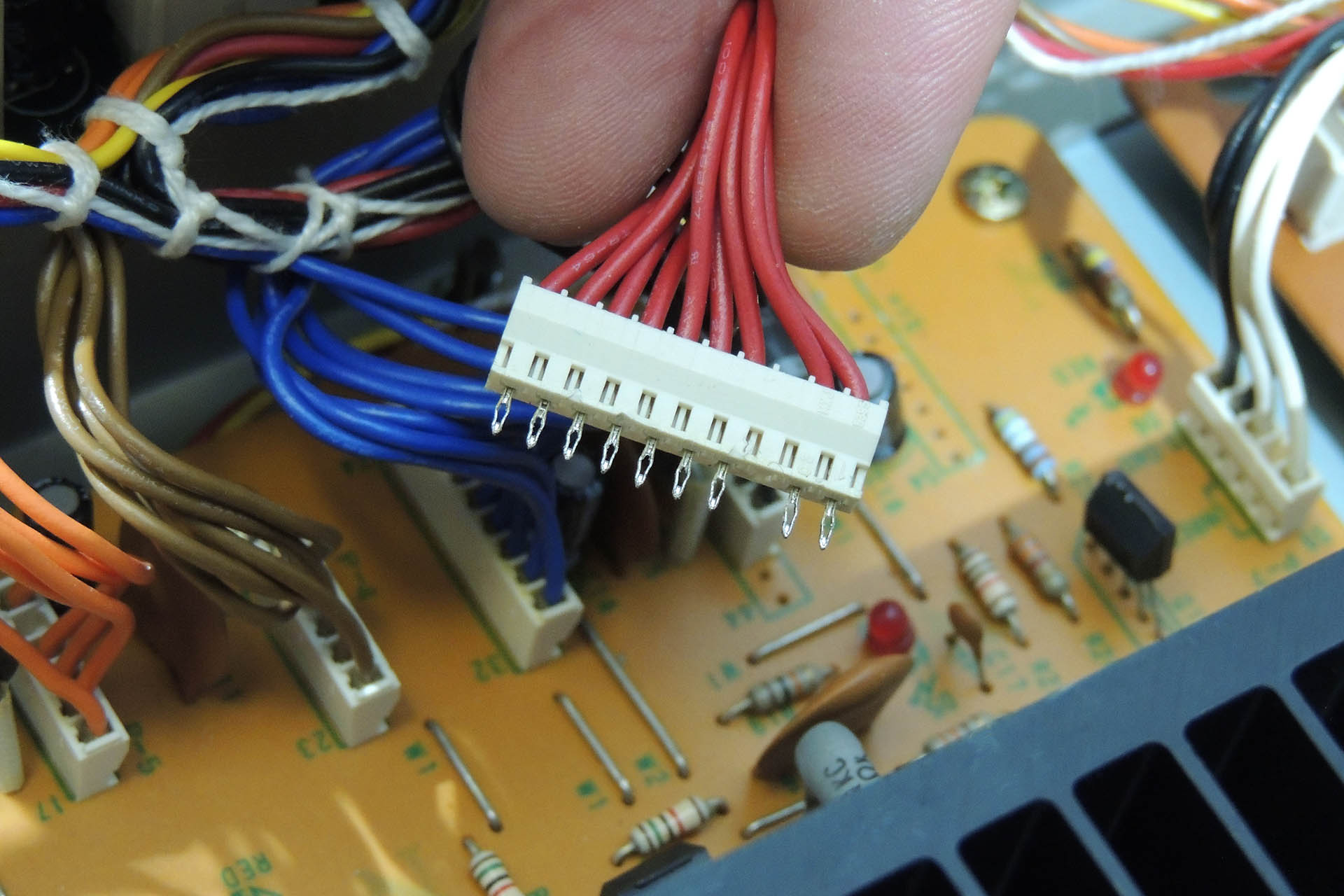
Don't simply cut the wires to the transformer and the terminals on the original power supply board. Instead, try to unwrap so as to preserve the original length of wire. You may trim some of these later but you don't want to be left short!
Require tools and equipment are as follows:
-
- Temperature controlled soldering station (e.g. Weller WE1010)
- Temperature controlled de-soldering station (e.g. Duratool D00672)
- Small wire cutters
- Small pointed pliers
- Adjustable cable strippers
- Set of cross-head screwdrivers
- Small flat-head screwdriver
- Set of box-spanners (metric)
- Tweezers
- Digital multi-meter (DMM)
PLEASE don't use a plumber's or electrician's soldering iron and please don't use a manual solder pump. You'll just wreck things. In fact, if you're thinking of using that kind of equipment, you shouldn't be operating on your MKS-80, let alone installing Aurora!
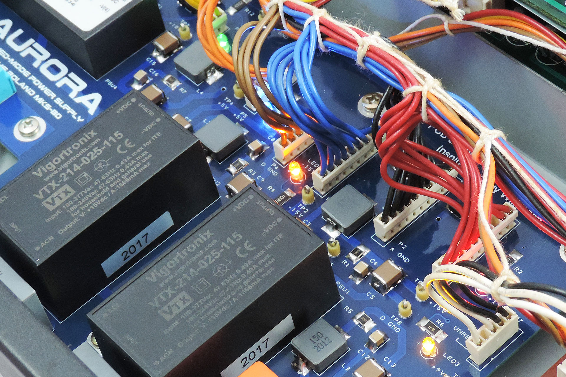
A few hints on workflow:
- Do NOT rush it! Take your time.
- Check and double check your work after each stage.
- Do not rely on the status LEDs as indicators of required voltages. Use the test points to measure the voltages with a DMM.
- When removing screws and nuts from your MKS-80, use a 'gently, gently' approach. You really don't want studs to loosen or threading to shear.
- Do NOT over-tighten screws and nuts. You're dropping a replacement power supply into a vintage synth module and not building a spaceship that's destined for the outer planets!
- The 10V reference has been set by me using a regularly calibrated DMM. Please do not mess with it!!!!!
- Note the orientation of the headers before you remove them. It's actually not too important other than to keep things tidy except... for P7. Unlike the other headers which each carry a single supply, P7 carries the 9V supply and a digital ground, to the programmer (MPG-80) port via the output board. It's VERY important that this connector's original orientation is maintained.
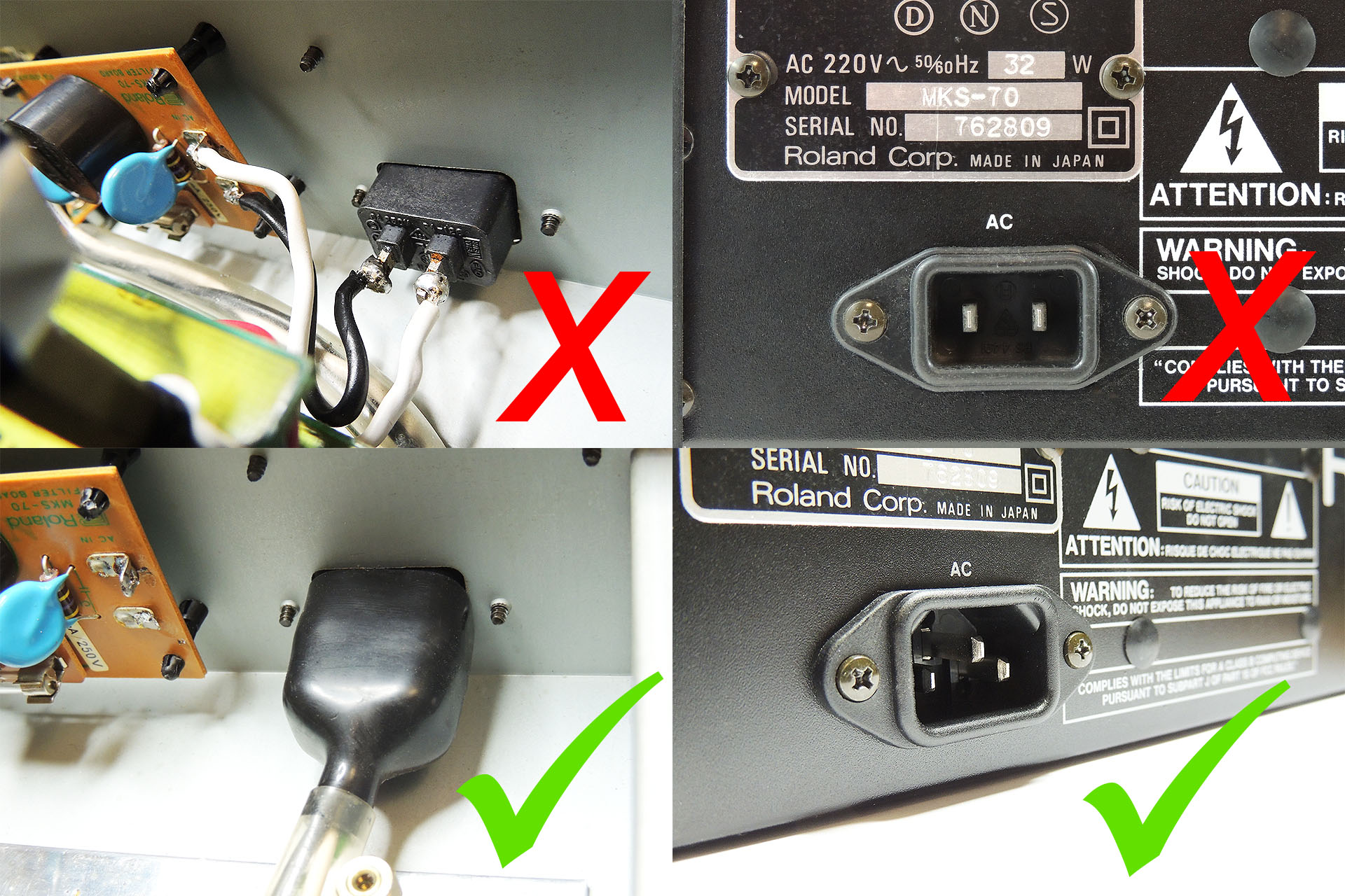
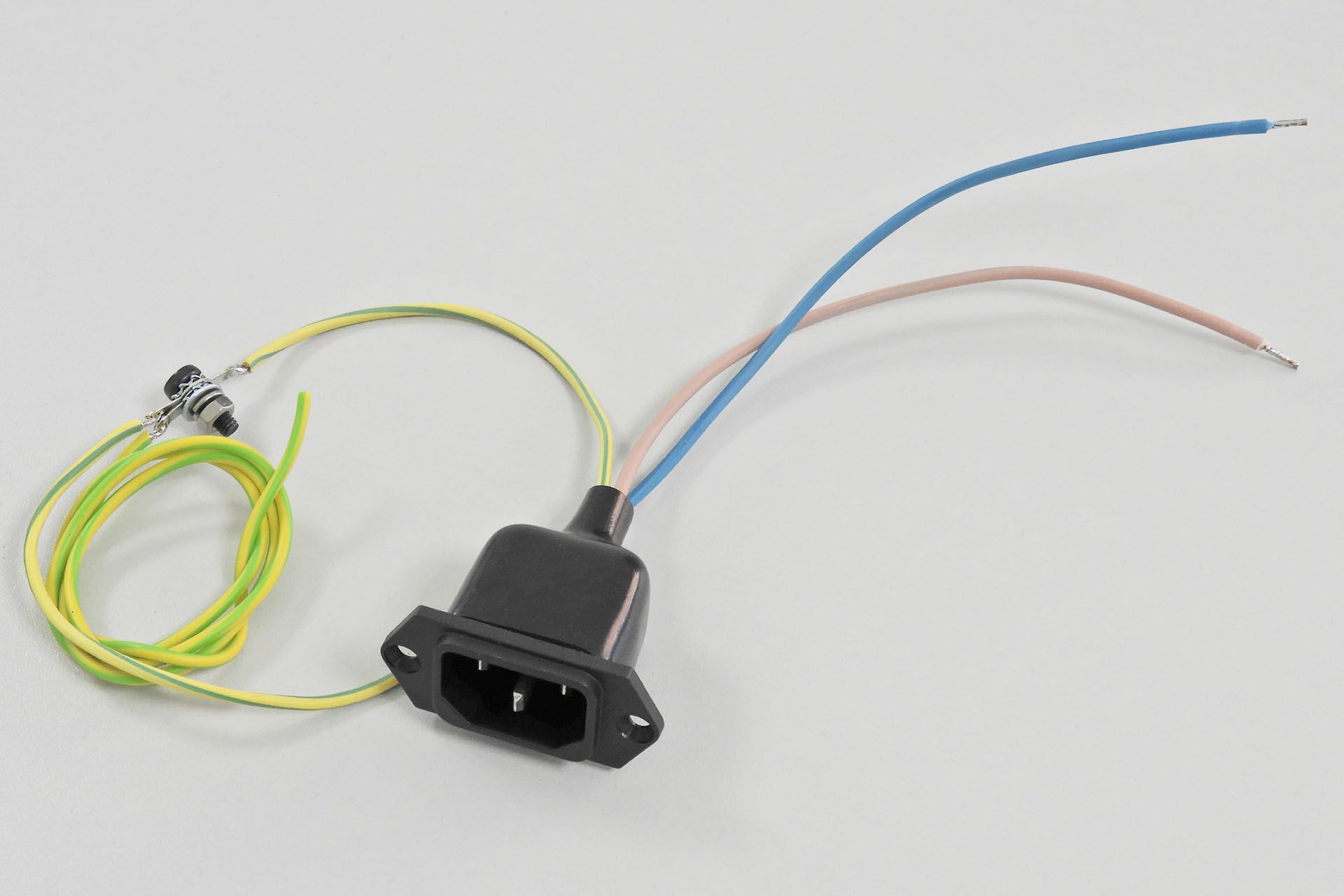
- Your MKS-80 MUST BE EARTHED. If you have a 2-pin IEC C10 mains socket, you must replace it with a 3-pin IEC C14 socket. The earth pin should be connected to the MKS-80 chassis. There's a hole in the lower case in between the mains socket and the side of the MKS-80 chassis which will take a M4 screw. DO IT!!!! Aurora board B must also be connected to this point.
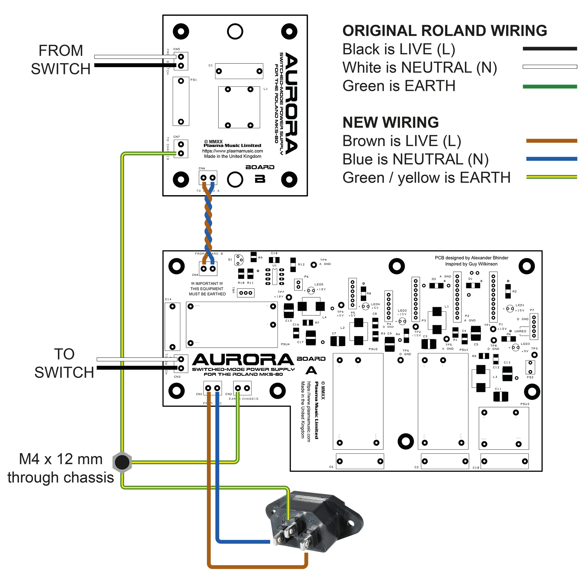
Here's a wiring diagram showing how the two Aurora boards are connected to each other, the mains input, the switch and earth / chassis. Also illustrated is the use of existing (original) wiring as well as some new wiring.
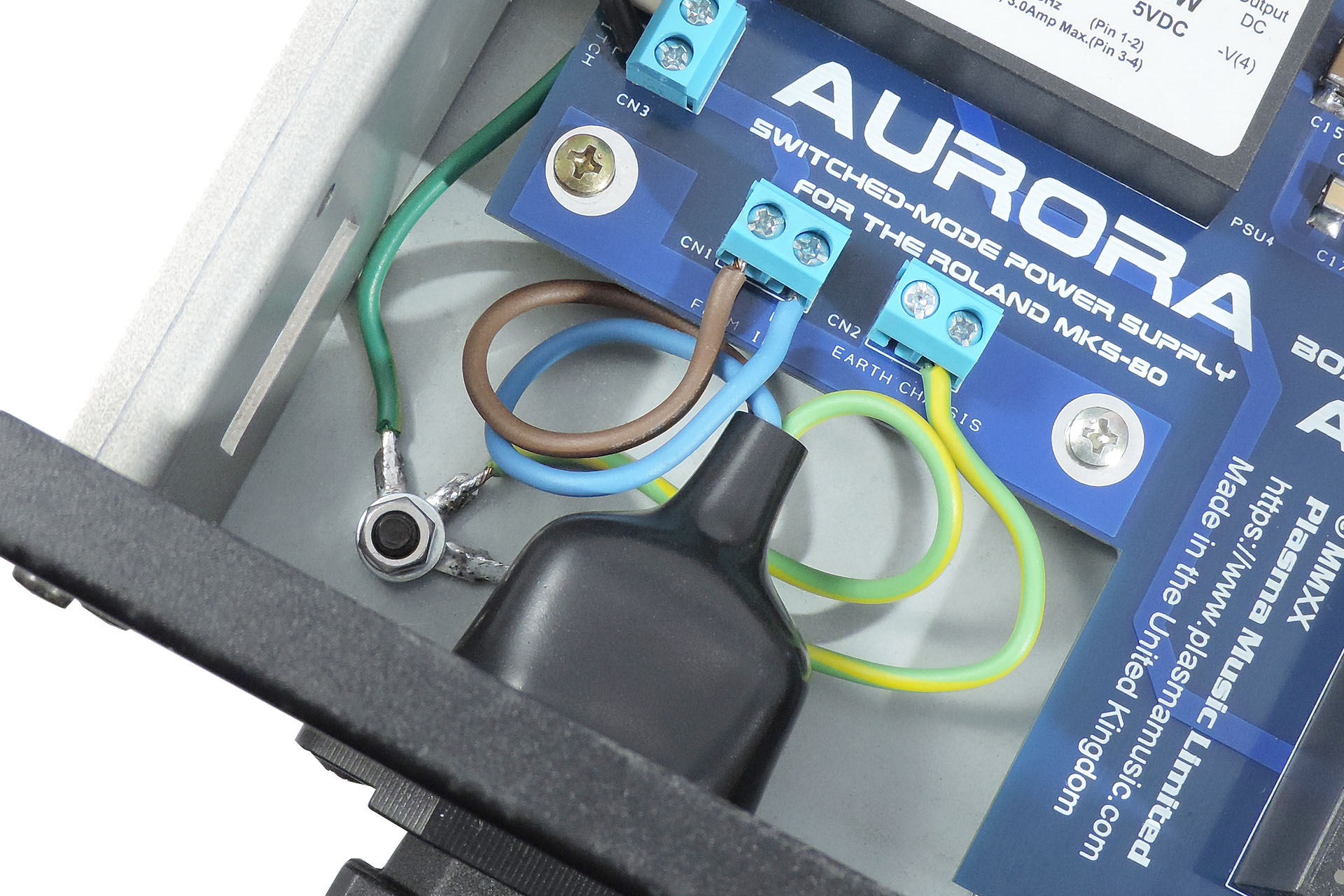
Aurora worked out perfectly. With overrated Vigortronix converters, there's a lot of headroom for the MKS-80 and on top of that, things don't get hot. The carefully designed filters on the back of each converter ensure that Aurora is dead quiet. These are important and you simply won't find them in a commercially available off-the-shelf power supply. Aurora retains a vintage feel with it's through-hole LEDs and fits perfectly into the space left after the original transformer and power supply re removed. No hum, no worries about collapsing supplies, a much lighter MKS-80 and everything's running nice 'n' cool. 😎
UPDATE - 7th October 2020
Since August's flood, I've had to move ops back home, temporarily. It's very cramped, things are taking longer (it took me two days to find my oscilloscope) but Julie my wife, is amazingly patient and understanding and a big support during this challenging time.
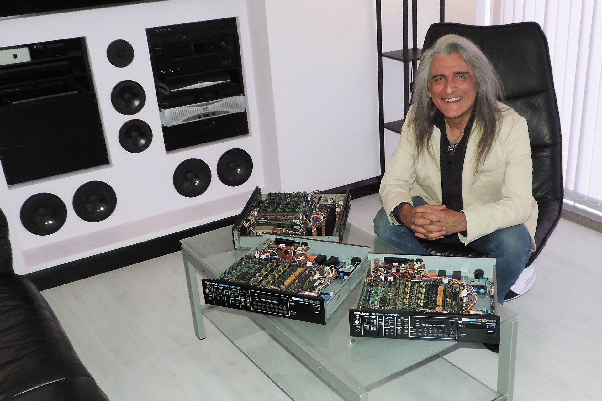
I currently have three MKS-80s in for Aurora and OLED module upgrades. Two of them have already been done but the fourth (a Rev 4 at the back), has a dead voice which I need to fix before I do anything else.
UPDATE - 2nd December 2020
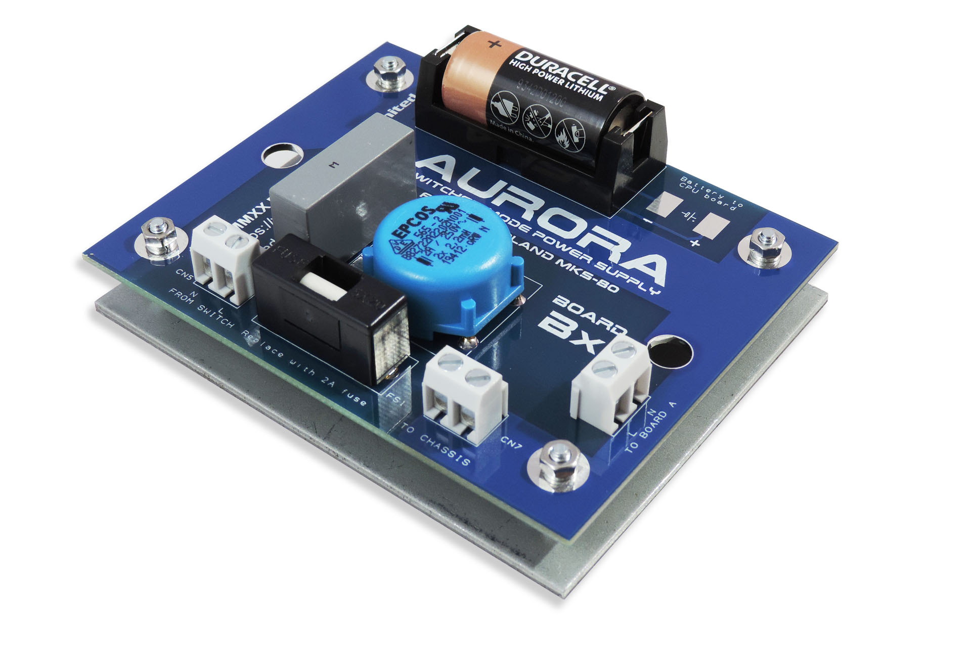
So the past few months has seen more than a few Aurora sales and installations. Many customers whose units I've had in, have asked if I could also install my Live Forever memory back-up battery mod and it got me thinking.
Aurora has two boards. Board B comprises mains protection and filtering so, not a lot. With a little nudging, I was able to fit a CR123a battery holder on to the PCB and so Aurora Bx Board was born! Read more about it here.
UPDATE - 24th December 2020
Aurora installation instructions are now available in German.
Die Installationsanleitung für Aurora ist jetzt in deutscher Sprache verfügbar.
UPDATE - 24th April 2021
Aurora is now offered with the optional V06 data cartridge re-enforcement bracket. Such a cool solution to a problem that many Roland MKS-80 owners will be familiar with, the V06 basically strengthens an undamaged cartridge slot and reinforces a broken one by putting 2mm of solid steel behind it!
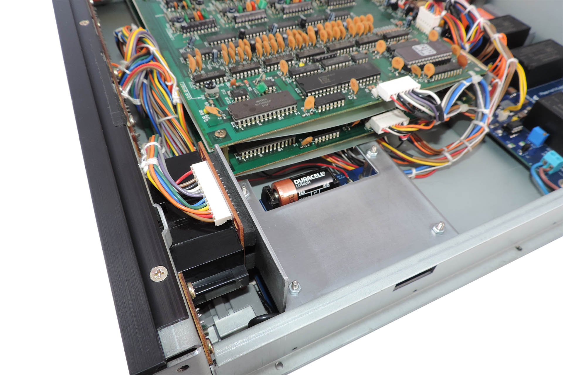
Existing Aurora customers take note; once your Roland MKS-80 is open, V06 can be installed in a few minutes, with just a M3 (5.5mm) nut-runner.
Read more about the V06 here.
UPDATE - 9th August 2021
Here are a few pictures of customers' own installations.

I'm deeply concerned about the environment and the exploitation of labour and so I always use local manufacturers in preference to the Far East, with the following in mind:
- I can be confident that workers are treated fairly and earn a proper wage.
- I can be confident of the standard of quality of each item that is delivered to me.
- Communication is important and using local manufacturers, all correspondence is quick and understandable.
- I believe in supporting the local economy.
- I can be confident that the disposal of manufacturing waste is managed properly and in accordance with national and EU law.
Using local manufacturers isn’t the cheapest option but the above points are important to me. I hope that they’re important to you too.

Please don't hesitate to contact me if you have any questions regarding the Aurora Replacement Power Supply for the Roland MKS-80 or, if you want to buy Aurora or book in your MKS-80 to have it fitted, please check out my store.

