
Inspired by the great work of Guy Wilkinson from supersynthprojects.com on his P0004 switched-mode power supply upgrade for the Roland Super-JX, I decided to have a go at designing a similar Roland MKS-80 power supply upgrade. As it turned out, Guy helped a lot. After all, he's done this kind of thing before!
So give me a little space here and allow me to explain the fundamentals of just how a conventional style 'linear' power supplies works...
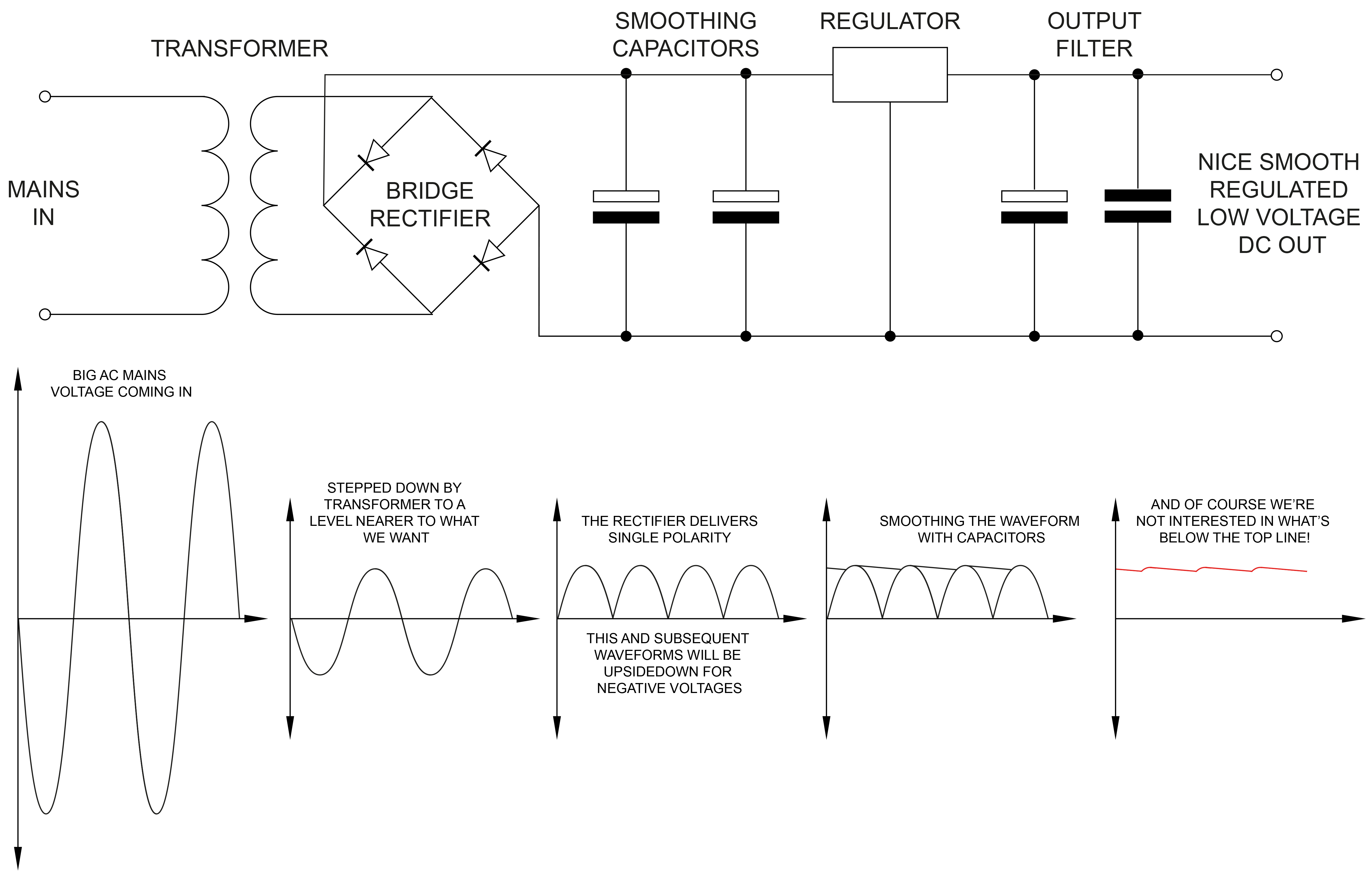
Firstly, what is a power supply? A power supply is a collection of components assembled to convert a domestic high voltage AC supply to one or several low voltage DC supplies suitable for powering electronic components.
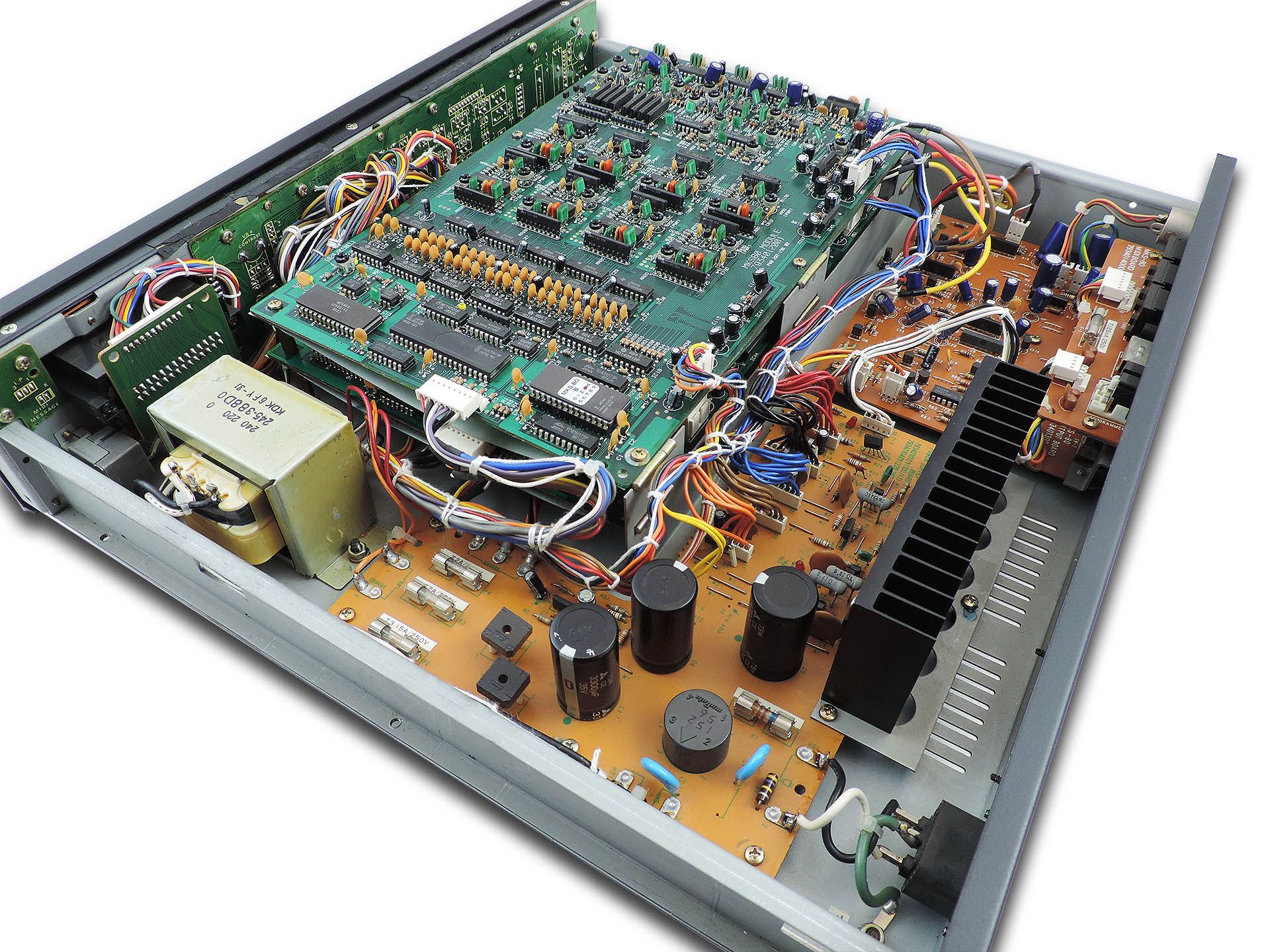
Mains voltage goes into the unit. Although always AC (alternating current in the form of a sine wave), the value of the voltage varies across the world from 240 V in the UK and Australia for example, to 220V in Europe, 115V in USA , Canada and other regions and 100 V in some other places. A transformer is used to ‘step down’ the mains voltage, to something close to what is needed to power the internal electronics. A transformer will often have a couple of 'secondary' windings which produce two or more independent low-voltage supplies.
 Here's the transformer in a Roland MKS-80.
In the MKS-80, you're aiming to get a few more volts than +/-15 V for the analogue electronics and +5 V for the digital. Then you might need a little something for say, a remote programmer. In older synths, you’ll also need a reference voltage for the VCOs, for example. In the MKS-80, this is 10 V and needs to be very accurate. It was also quite common to generate other voltages, sometimes complimentary. In the MKS-70 for example, +/-5.6 V are produced on the CPU-board and in the MKS-80, each voice-board has a small circuit which produces +/-7.3 V. These voltages were derived from main supply lines such as +/-15 V from the power supply.
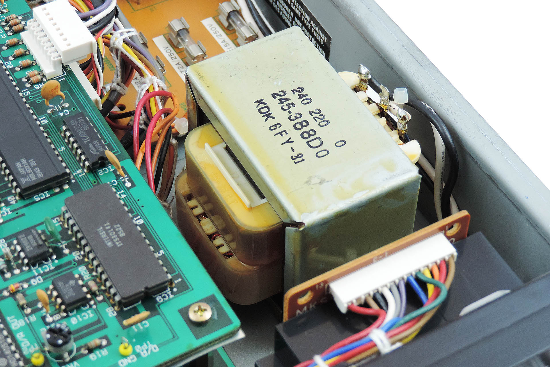
After the transformer, the voltages are still AC meaning that they’re still in a sinusoidal form swinging between positive and negative at either 50 or 60 Hertz (again, depending on where you are in the world). You need to ‘rectify’ these AC voltages which is the first stage to approximating towards DC voltages of a single polarity (plus or minus) and then you need to smooth out the result, with big capacitors.
Finally, you need to ‘regulate’ the voltages. The regulator stage performs two jobs; the first is to deliver the actual voltage required. The input voltage to the regulator will be a few volts more than what comes out from the other end. The regulator 'absorbs' the difference between the input and the output voltages and dissipates this as heat. The second job of the regulator is to maintain the required voltage as the demand for current varies.
So, you normally have one big transformer with perhaps a couple of secondary windings to bring things down. After the transformer, you'll have a couple of rectifiers and then one regulator (and associated filter circuitry) for each supply.
It doesn't stop there. You may have noticed that some power supplies are 'larger' than others. Obtaining the desired voltages is one thing but electronics needs current. The product of DC voltage and DC current is 'power'. So more powerful power supplies are... well, bigger!
Still with me? Good!
Modern switched-mode power supplies do exactly the same job but work quite differently and probably the main physical difference is the absence of a transformer. This omission is generally a big space-saver. When however, you’re requiring several independent voltages in the same box and you basically need one AC/DC conversion stage per voltage, things can get a little crowded.
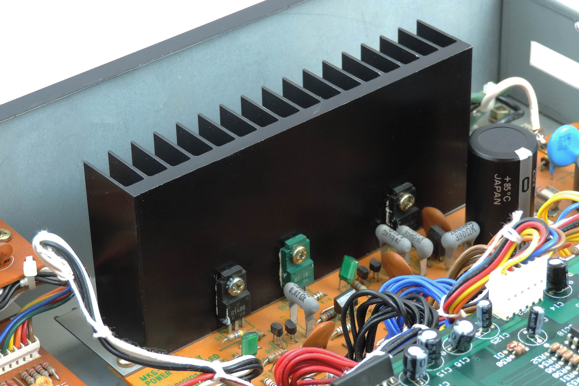
Switched-mode power supplies are considerably more efficient than their equivalent ‘linear’ cousins so generally they don’t get too hot. Some will be familiar with the sometimes, huge amount of heat-sinking present on linear power supplies and the case venting that used to go with them.
Due to the way they work, switched-mode power supplies can be plugged into virtually any mains supply unlike linear supplies which will require the ‘taps’ on input side of the transformer to be changed… if you’re lucky. Some older equipment would require the whole transformer to be replaced, when changing mains voltage! Oh, those were the days. Since that's virtually impossible all these years later, users of equipment that would have required a transformer change to operate in their region, can only opt for using an 'external' transformer which steps the mains voltage up or down from their region to that which the respective equipment was originally manufactured to operate in. What a drag.
So, if you have a MKS-80 that you acquired from another region and you use an external transformer, fitting an Aurora module into it, will allow you to plug your machine directly into your mains supply. 😎
So truth be known, both linear and switched-mode power supplies have their respective challenges and if not designed properly, can cause undesired side-effects, compromised performance or reduced life expectancy.
In a linear power supply, initial conversion of AC to (a type of) DC is performed by rectifiers, the output of which is 'smoothed' by large capacitors. If not chosen carefully, smoothing might be compromised thereby producing hum. Large capacitors are expensive and take up precious space and over time, the dielectric material inside them deteriorates, thereby reducing their effectiveness. Discrete or comprised linear regulators are very inefficient and can require considerable heatsinking, again increasing cost and demanding even more space. Apart from being a considerable lump of iron and wound copper, transformers generate electromagnetic fields which are seriously not wanted in audio equipment.
Switched-mode power supplies also have their issues. If designed like Aurora which comprises discrete AC / DC converters, issues such as switching noise are greatly reduced. Due to the nature of operation, there is no hum. Neither are there large capacitors that will over time, deteriorate. On the backend of Aurora’s AC / DC converters are additional filers to virtually remove further noise. And of course as has been previously mentioned, the efficiency of switched-mode supplies means that there is no requirement for huge heatsinking.

Since Roland launched the MKS-80 in 1984, electrical safety standards have changed considerably and it's important that anything designed today, which is to be made available to the general public, complies with modern regulations. In fact, the decision to make something like Aurora, which potentially can be fitted by 'anyone' was the hardest. On the other hand, there are disclaimers! Follow the rules and everyone should be just fine.
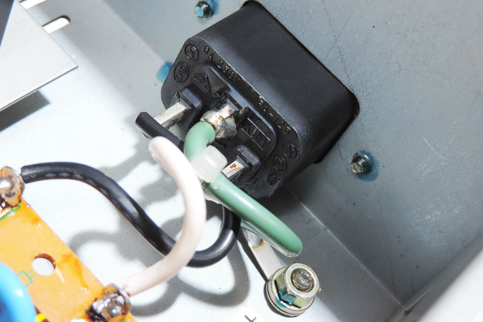
EARTHING ISN'T JUST ABOUT SAFETY!!!!
 Back in the day, a lot of Roland equipment was shipped with 2-pin IEC C10 power input sockets. Due to the way in which switched-mode power supplies work, specifically the filters, it's important that your MKS-80 is properly earthed. If your MKS-80 has a 2-pin IEC C10 power socket, then you will need to replace it with a 3-pin IEC C14 socket. This item comes as part of my earth bonding kit and can be purchased when you buy Aurora.
A CHANGING WORLD
It’s Spring 2020 and the world has been hit with COVID-19. Countries try to protect their citizens by declaring lock-downs. It’s a depressing time and hundreds of thousands die across the world while many are left alone with the stress of isolation. 2020 is turning into a time for reflection and the global community begins to realise that things might never be the same again, at least for the foreseeable future.
I was lucky, very lucky. I was at home with my lovely wife and one of my daughters who had come back from university, just before the lock-down was announced here in the UK. After a few days, I set up my laptop on the dining room table and came up with a couple of projects, simply to pass the time. One of them was 'Aurora'; a Roland MKS-80 power supply upgrade. I won't bore you with the other ideas.
A QUICK STEP BACK
Just before the lock-down, I had a couple of Roland MKS-70s come in for repair. Having one of these gorgeous synth modules myself, during the repair process, I got quite into the world of Super-JX upgrades. You can read more about that here. Having got to know Guy Wilkinson and also being the proud owner of a Roland MKS-80, one thing led to another.
The first two or three weeks were spent making physical measurements. I needed a board size! Since the massive heat sink would be redundant, I planned to take advantage of that space. Measuring, re-measuring and measuring again... many of the spaces between the mounting studs didn't seem to be exact integers, hence there was always a glimmer of doubt in the back of my head.
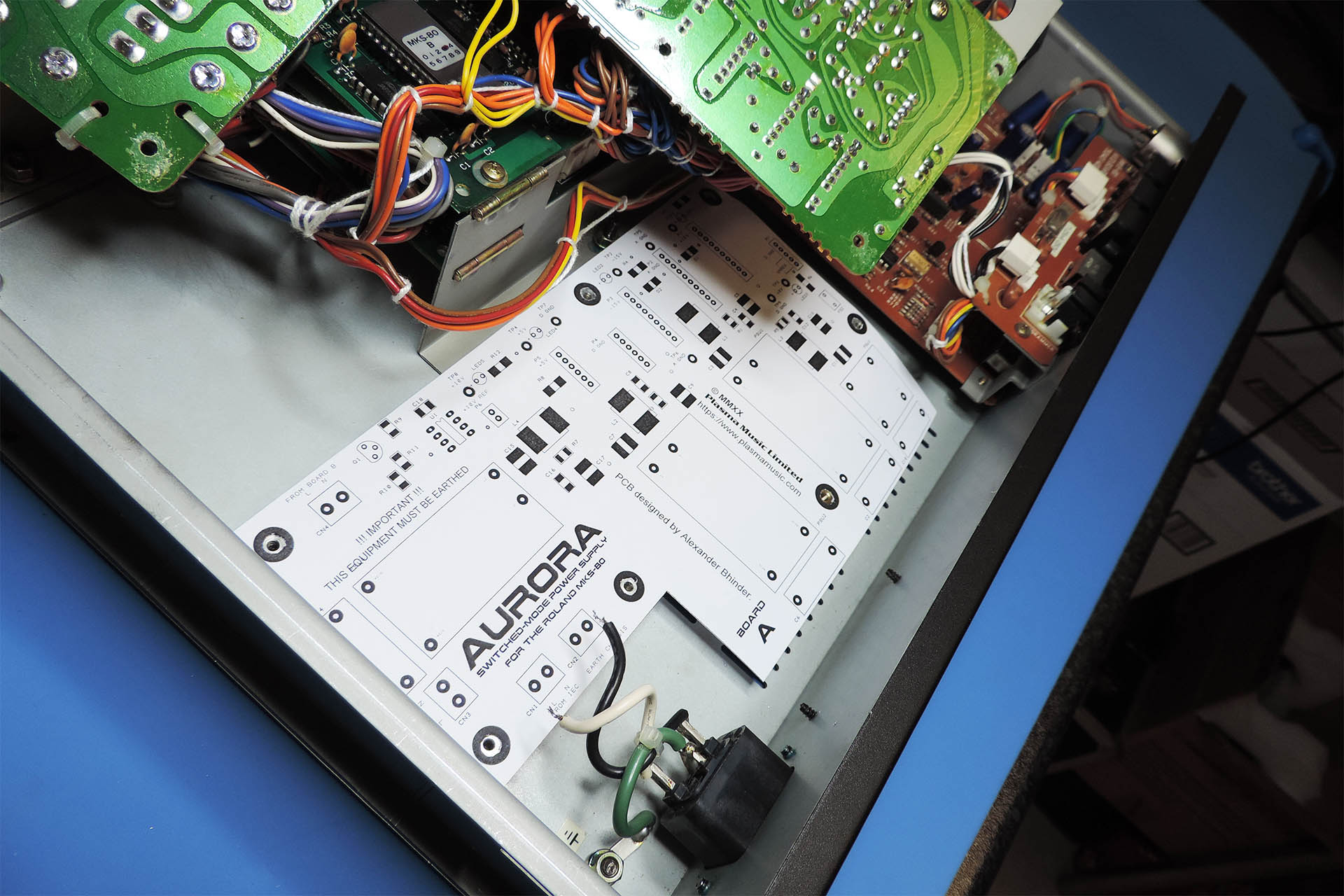
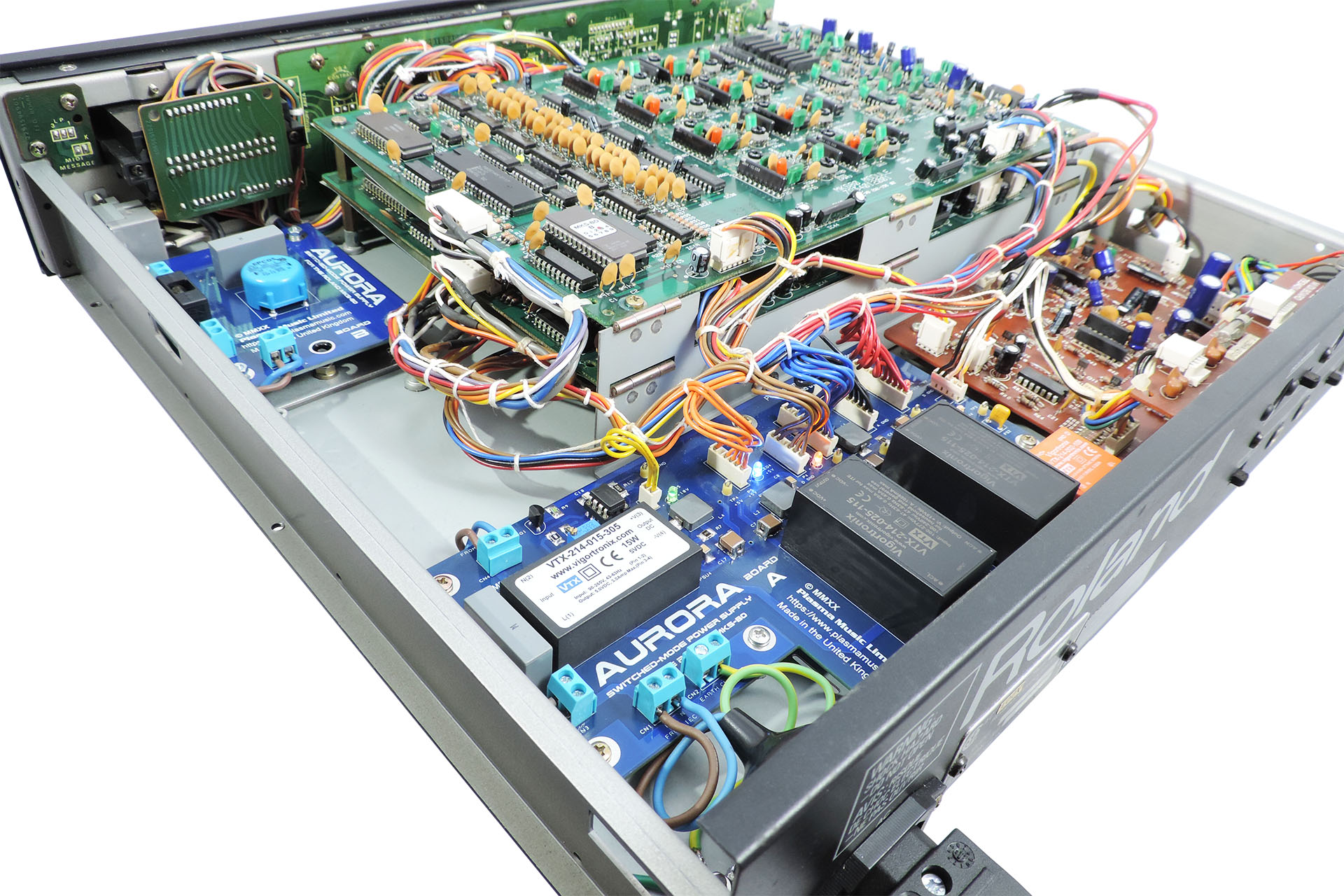
The design started off with the idea of using the same board dimensions as the original MKS-80 power supply. I just extended it to take up the area that was occupied by the heat-sink. As things progressed however, it was obvious that this would be an expensive approach and any consideration of commercial supply would be ridiculous. The PCB would require a panel measuring a massive 280mm x 210mm. The board is L-shaped and so, after cutting, that would mean a wastage of over 35%. The board would have been way too expensive to have been viable so annoyingly and after several design revisions, I decided to completely change my approach to using two boards; one, a regular rectangular shape, which would occupy the main area of the original board and heat sink and which is known as Board A and a second board which would accommodate the front-end high-voltage components and which would mount where the original transformer was, known as (you guessed it) Board B.
I must confess that despite having spent the past thirty-five years servicing studio equipment and having been Roland UK's Group Service Manager in the late eighties, I was still very apprehensive about operating on my own lovely MKS-80, which I bought from Roland as a staff purchase and which is in beautiful condition.
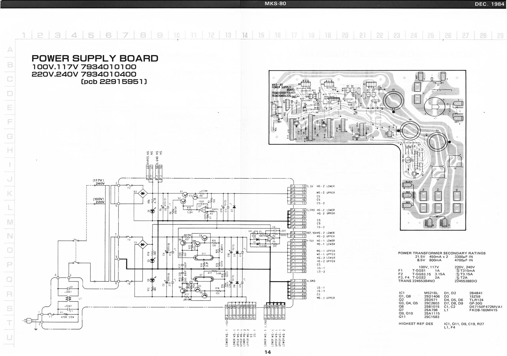
Unlike the MKS-70, the headers that distribute power to the CPU-board, voice-boards and output-board in the MKS-80, are grouped by voltage as opposed to destination. This means that all the +15V supplies are on one header, all the -15V supplies on another and so on. Also unlike the MKS-70, the MKS-80 PSU headers are soldered at the power supply end, to the PCB. Another consideration was the classic Roland nice 'n' tidy wiring loom. Ideally I wouldn't want to mess with that so I figured on trying to preserve the relative positions of the header connectors as best as I could.
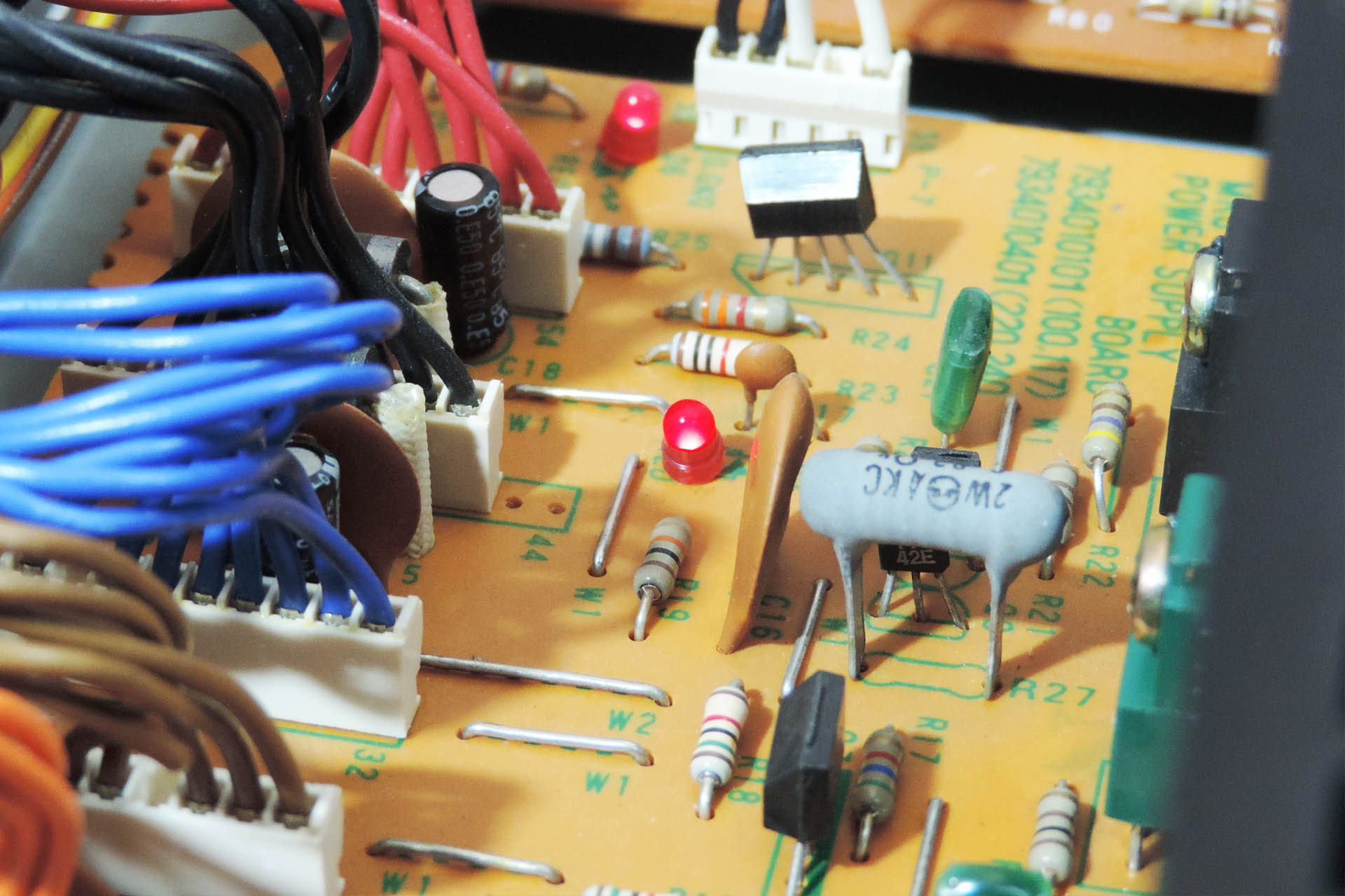
There are two other marked differences between the MKS-80 and MKS-70 power supplies; the MKS-80 has a precision 10V reference source, used for the VCOs. It also has cute little status LEDs which indicate power on the various voltage output lines!
Anyway, after some time, I felt as though I'd done enough measuring and so the next stage was to work out the current demand on each line. The unregulated supply wouldn't want too much as it's used to power a MPG-80 programmer / editor, when connected. According to the Roland service notes, the power consumption of the MPG-80 is 0.9W. With on-board 5V regulators, that means that the current drawn is about 180mA.
The 10 V reference source is just that, a reference and so current requirement isn't an issue. That means we're left with +/-15V for the voice boards and +5V for the CPU board.
I so didn't want to start messing around with my MKS-80, lifting components and possibly even cutting tracks, so I decided to try to work out current requirements from the schematics in the Roland service notes. I also used Guy's results from his P0004 MKS-70 power supply project, as the two machines are kind of similar.
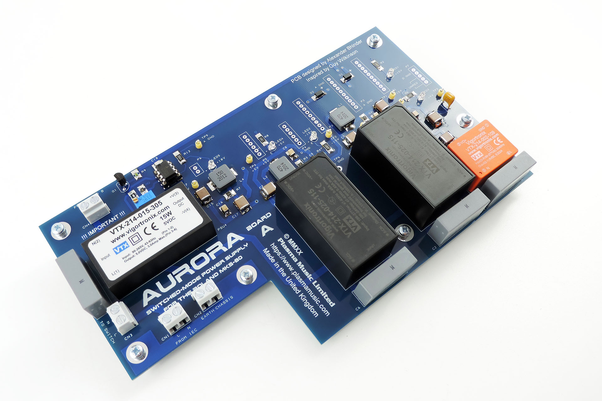
Although more expensive, I went for Vigortronix AC/DC converters. Vigortronix is just down the road from me and I've been using their transformers for many years. Technically, the specifications of the Vigortronix converters seemed much better than the Mean Wells with for example, less leakage.
After having taken my best shot at estimating current requirements, I chose 25W converters for the +/-15V rails and a 15W converter for +5V rail. The power ratings of the converters would theoretically mean that Aurora would run quite cool. For the 'unregulated' supply to the programmer port, I chose the Vigortronix 9V version of the 2W converter which will deliver 222mA.
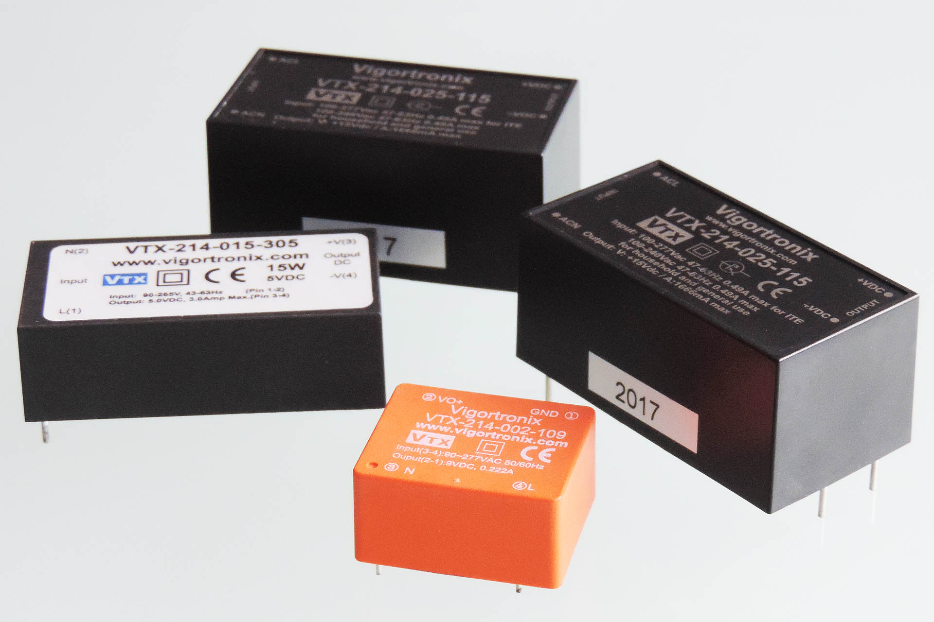
The 9V supply is being sent outside of the MKS-80, so Roland decided to protect it with a 125mA fuse which resides on the MIDI board. I've gone a step further and dropped in a resettable fuse in line with this supply.
I decided to use through-hole T-1 3 mm LEDs instead of the surface-mount devices that Guy used on his P0004. I figured it would introduce a little retro into something that's so hi-tec in comparison to the original PSU. Back in 1984, I don't remember seeing anything other than red LEDs. This time around, I decided to give each supply, a different colour. Yeah, what the hell? And don't forget the 10 V reference source. Originally I had no intention of putting a LED on this circuit but I eventually caved in. 😎
As I worked on the PCB design, I still had some concerns regarding the circuit design. Check out the tolerances of the supplies as specified on page 22 of the original Roland service notes:
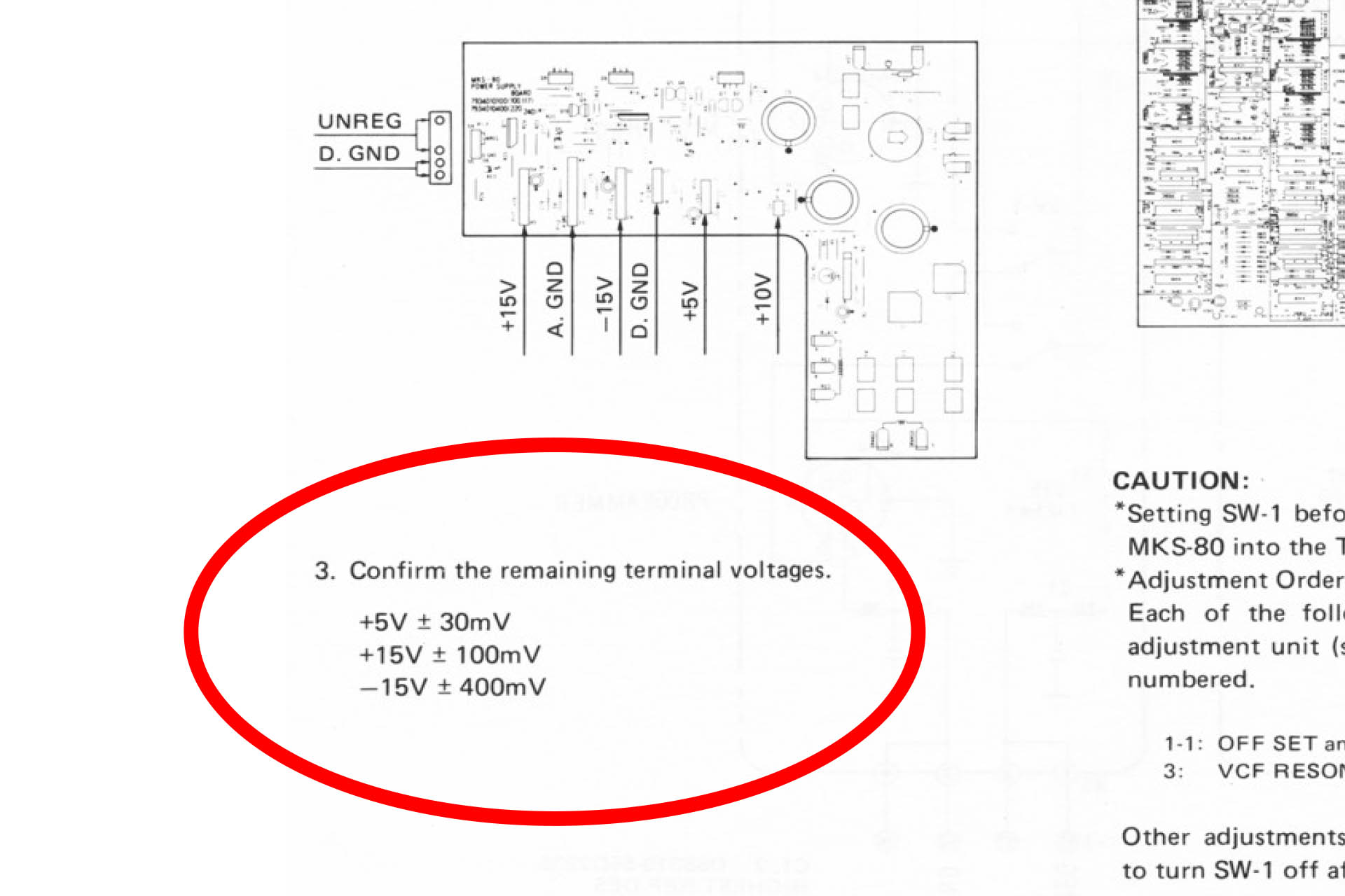
Two of those figures are tight, with about 0.6% tolerance on the +5V and +15V lines. Although not impossible to achieve with the type of power supply that's being discussed here, it's not easy and such tight tolerances could be a problem. Typically, AC/DC converters have an accuracy of between 1% and 3% and of course there's a small voltage drop across each all-important filter.
Out of interest, I measured the voltages on my own MKS-80. Here's what I found:
+5V line measured in at +5.01V (10mV ∼ 0.2%.)
+15V line measured in at +15.08V (80mV ∼ 0.53%).
-15V line measured in at -15.10V (100mV ∼ 0.67%).
WOW!!!!! And that's after over thirty-five years! Roland sure could build power supplies.
Well, this realisation was kind of depressing and potentially the whole project could now be in jeopardy and might even end up being a complete and utter waste of time. 🙁
Incidentally, the Roland Jupiter 6 power supply is very similar and has exactly the same tight tolerances.
I carried on carefully studying the service notes. I looked over the schematics many, many times. I just couldn't find any reason for the high level of accuracy specified for the +5V and +15V rails and yet the accuracy for the -15V line was pretty average. The CPU-board should work fine on a little less than (bang-on) 5V. In fact slightly lower would be better. Although the critical 10V reference voltage is initially derived from the +15V rail, the fact that it's adjustable means that not even this would require such a tight tolerance on that supply.
So despite the fact that the thought of blowing up my MKS-80 if I was wrong, was constantly at the back of my mind, I decided to carry on.
The circuit for the Aurora was actually quite simple, to be honest. The PCB layout however, was not. Guy and I communicated almost every day while I was designing the PCB. In fact I only hope I wasn't too much of a pain for him! His extensive knowledge and experience of power supply filter design however, proved invaluable and we both shared a mutual attention to detail. Quite honestly, I couldn't have delivered this project without his help and so I'm actually considering the Aurora, a co-design effort. Thanks, Guy!
UPDATE - 5th SEPTEMBER 2020
Ordering prototype PCBs is a slightly nerve-wrecking experience and by the beginning of August, having made several tweaks to the PCB layout, I was waiting for the fourth and final version to be delivered. Then, on 12th August and after a major storm, my studio got seriously flooded. The experience was devastating. You can read about it here. Sod's law; the day after the flood, my final version PCBs arrived. In fact, that week was supposed to be the week that I officially launched Aurora but it all went kinda wrong due to the flood.
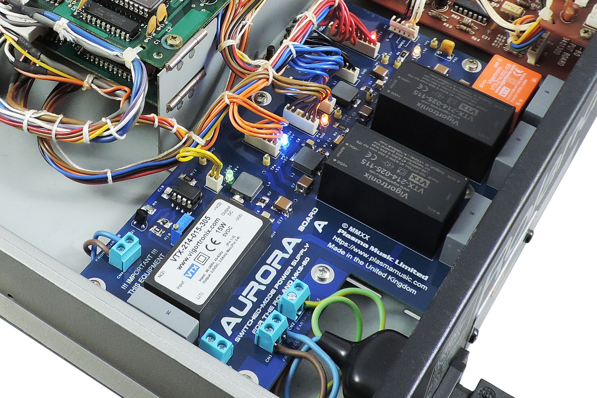
Once all my gear was safe and I had a plan in mind on how to move forward, I built a couple of Aurora boards and (somehow amidst all the chaos and my profound feeling of utter devastation) found the courage to drop a set into my own MKS-80 amidst the chaos and devastation of the flood aftermath. What was I thinking?!?!?
Anyway, I couldn't believe it. A bit of good luck for a change. WOW!!!! It all worked. Measuring the supply voltages, everything looked just perfect with +15.00V, -15.07V, +4.97V and +9.01V using the sample converters that Vigortronix sent me. There was no hum on the audio and it was remarkably quite, too. After an hour of being on, the converters were only slightly warm. This was great news.
Over the next few days, I put Aurora through its paces. Like many switched-mode power supplies, Aurora doesn't like being switched on and off in quick succession. That's probably not a good thing to do to your precious MKS-80, anyway. It's not a light-bulb!
Aurora worked out perfectly. With overrated Vigortronix converters, there's a lot of headroom for the MKS-80 and on top of that, things don't get hot. The carefully designed filters on the back of each converter ensure that Aurora is dead quiet. These are important and you simply won't find them in a commercially available off-the-shelf power supply. Aurora retains a vintage feel with it's through-hole LEDs and fits perfectly into the space left after the original transformer and power supply re removed. No hum, no worries about collapsing supplies, a much lighter MKS-80 and everything's running nice 'n' cool. 
While my MKS-80 was open, I took the opportunity to fit one of Guy Wilkinson's OLED modules.
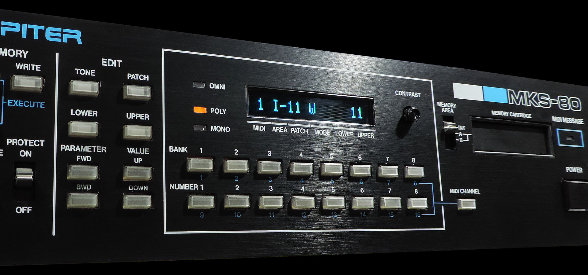
Okay, so the display on the MKS-80 doesn't really tell you too much but the new OLEDs do look really cool. More importantly, you don't have to worry about the old LCD backlight packing up or the inverter starting to whine. In fact I pulled the coil and the transformer from the CPU board, as they're completely redundant, now. 😎
Anyway... designing Aurora was a challenge but thoroughly enjoyable and I learnt so much. A working modern power supply for the Roland MKS-80. Wow! 🙂 With Aurora now finally working and really well tested, please read my official post here or just buy it here: