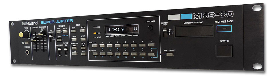
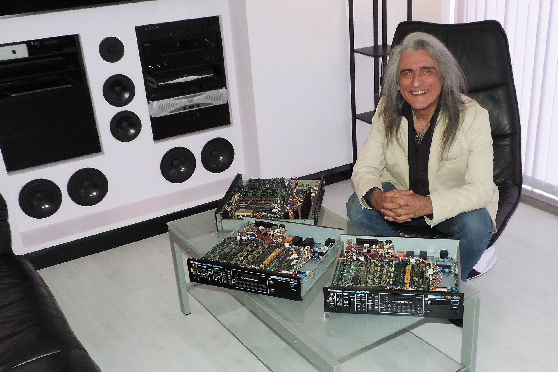
Towards the end of the summer, one of my regular customers brought me a Roland MKS-80 for repair and full upgrade. While previously upgrading Jay's MKS-70, I mentioned my Aurora project to him and also showed him one of Guy Wilkinson's OLED modules that I'd installed in my own MKS-80. Jay was already familiar with my Live Forever battery upgrade.
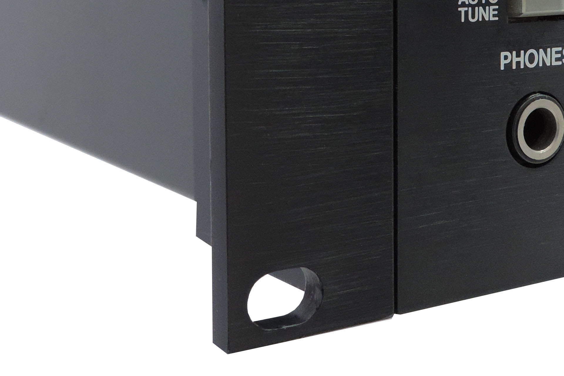
New rack-ears fitted to Jay's MKS-80.
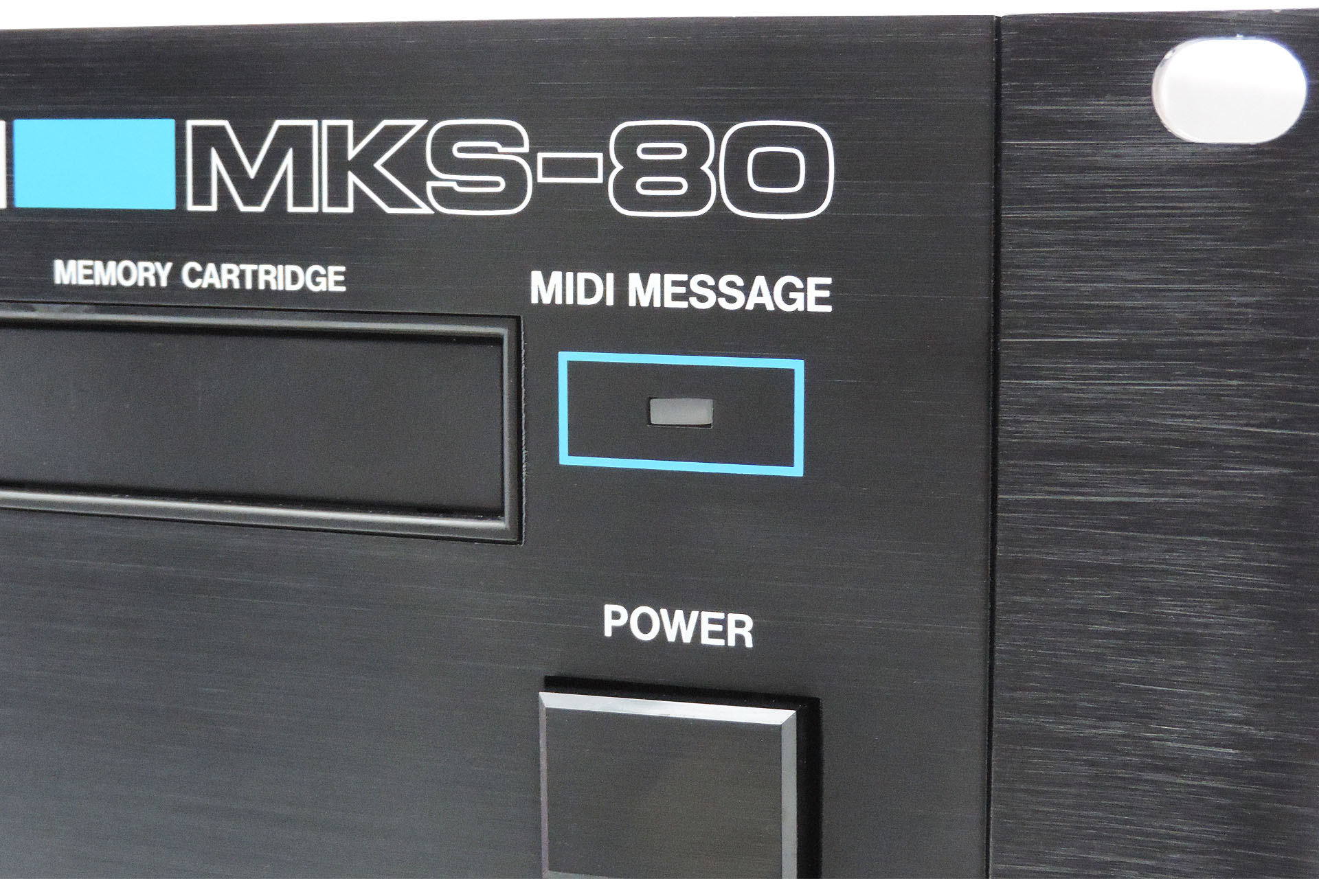
Jay bought his Rev. 5 from Japan and while in excellent cosmetic condition, it did have a fault. Depending on the tone and parameters, one of the voices was either distorting or not tuning properly. 🙁
After learning about Aurora and seeing one of Guy Wilkinson's OLED modules in the flesh, Jay was keen to have his MKS-80 upgraded as well as repaired. As it turned out, Jay was going to be my very fist Aurora customer and we were both very excited.
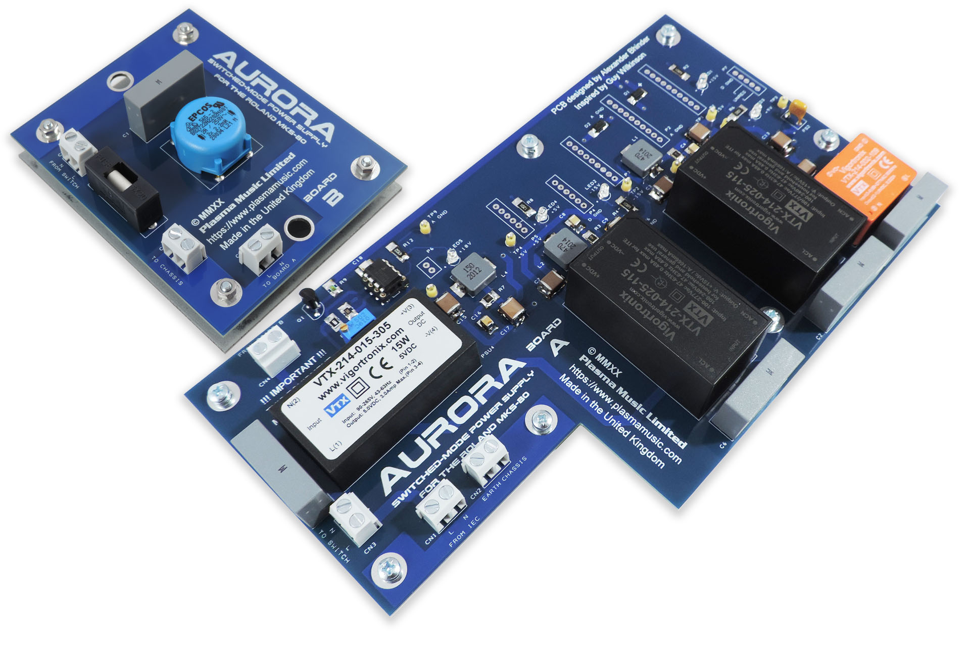
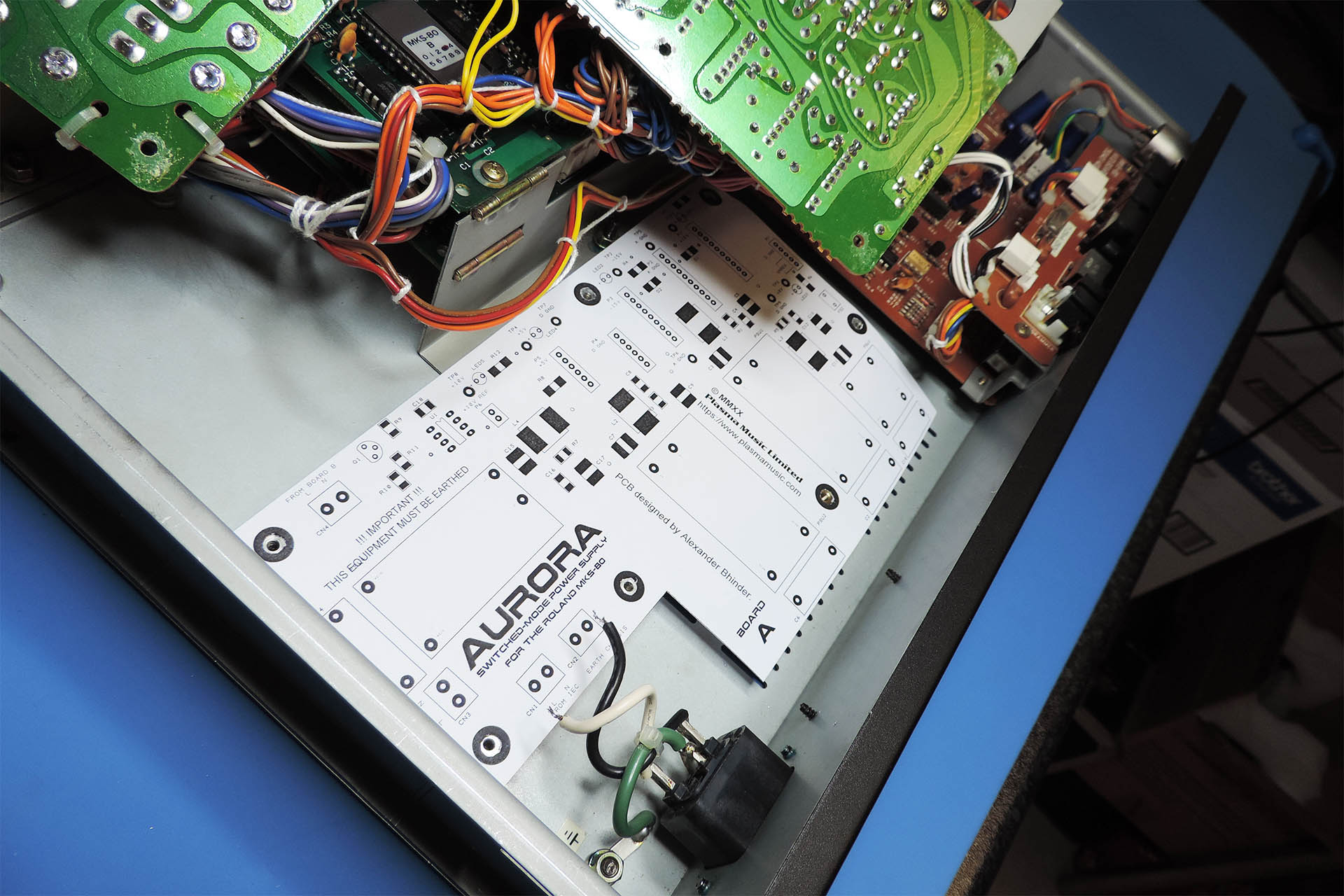
Aurora, the world's first switched-mode power supply for the Roland MKS-80 and Jay is my first customer.
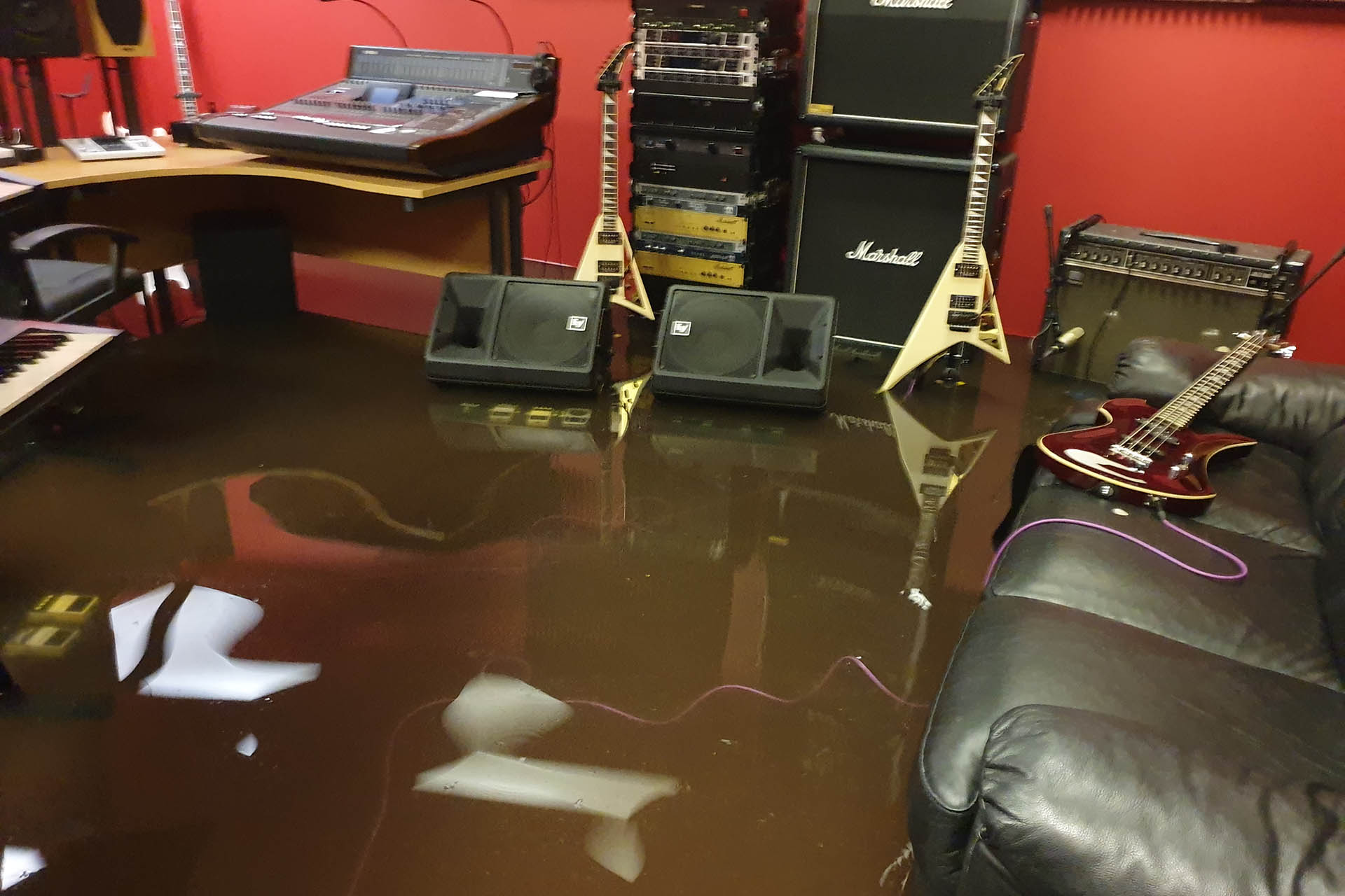
Then, on 12th August, things turned upside-down for me as Hemel Hempstead got hit by a storm which overwhelmed many drainage systems, including one which was in the road leading down to the rear of my premises. Within ten minutes, my studio floor was under more than 20cm of dirty flood water.
A truly devastating experience. Many thanks to friends and family who helped me through the worst of it.
Over subsequent weeks, My wife Julie, my youngest daughter Tsunami and I cleared out the rest of the studio. The lab was left 'till last however, as I had several customer units which were in mid-fix, Jay's MKS-80 being one of them. I also had to dry out and repair a lot of my own gear. It been a heavy few weeks with very little sleep.
Before proceeding with any upgrades, I wanted to fix the distortion / detune issue on this machine. The MKS-80 is very involved and the interdependencies between the analogue sections and even individual components, can yield some very surprising and unexpected results. Despite knowing this machine inside-out, fault-finding isn't always that straight-forward. I got there in the end though and changed two CEM3360 VCA chips, always dropping in turned-pin sockets when I do swap out ICs.
My rack-ears have a horizontally running mill-finish, just like the originals.
I'd already built and installed Aurora into my own MKS-80 so I was confident on the process and that it all worked. Doing the same for someone else's unit is still a little daunting, though.
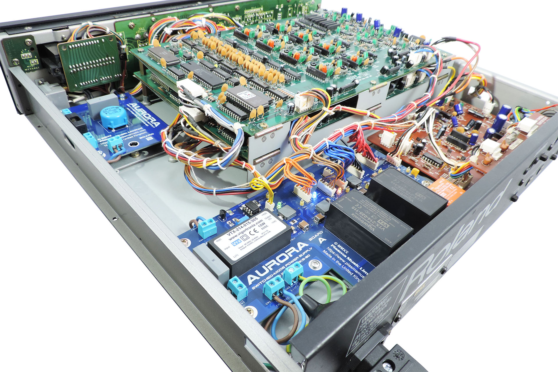
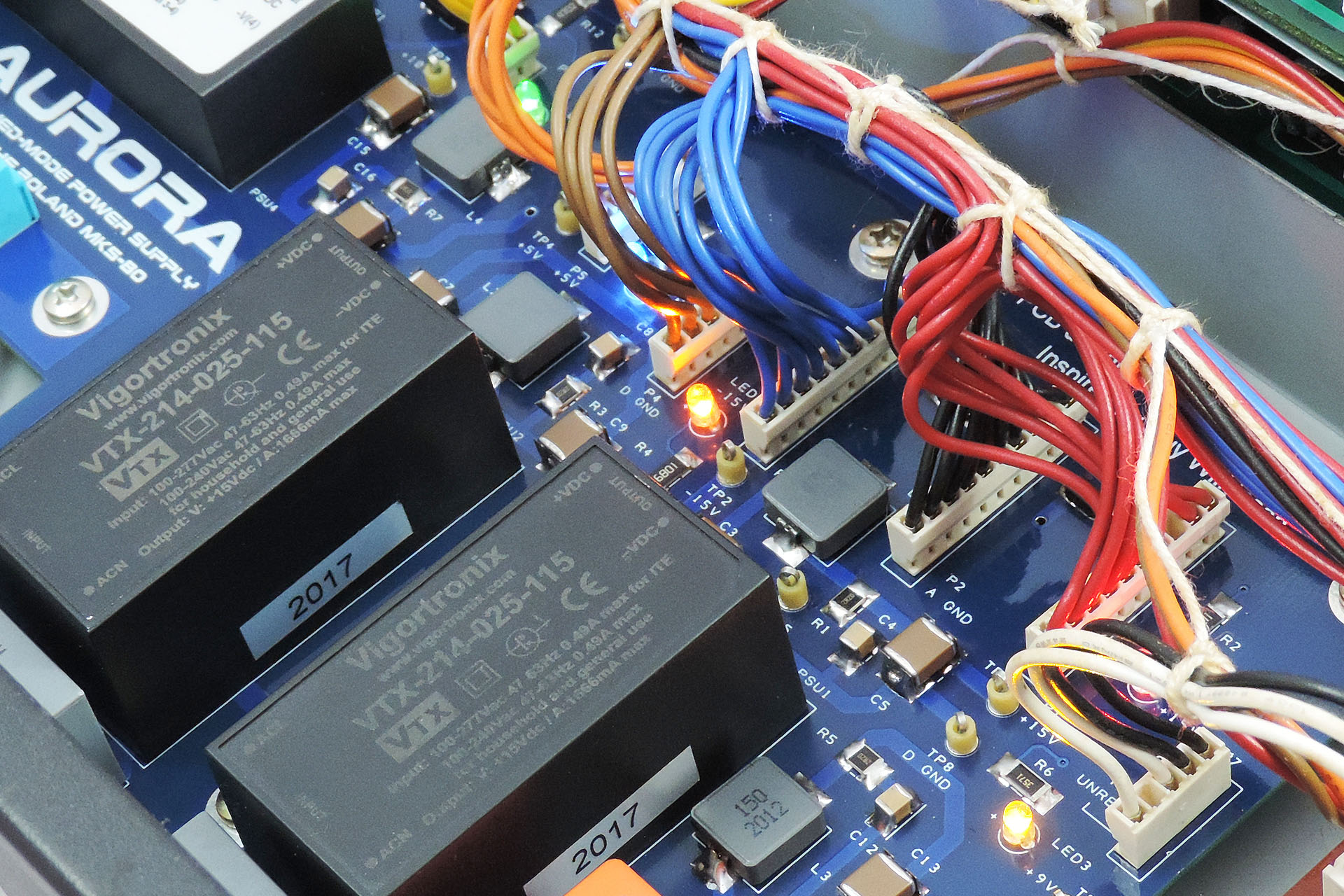
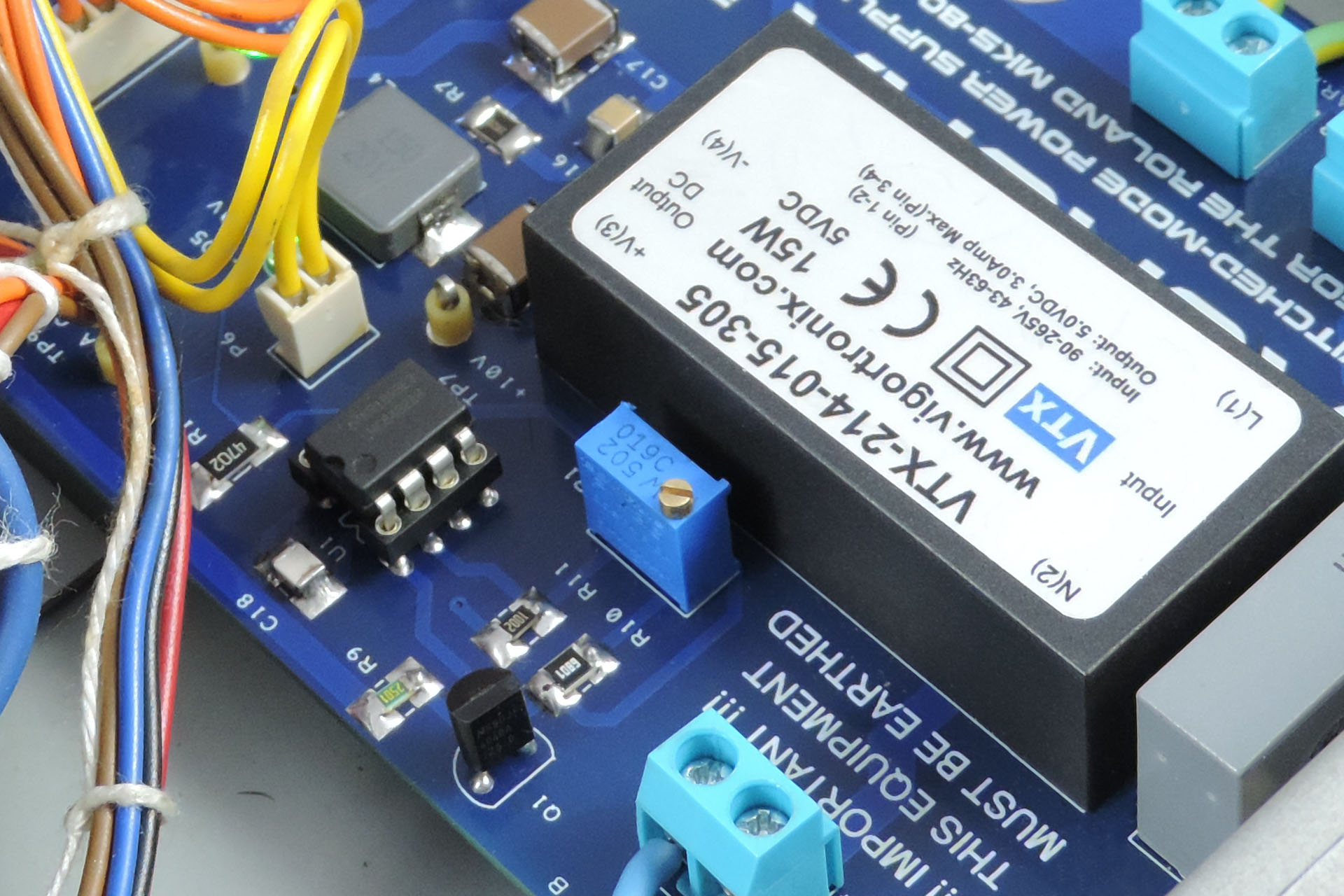
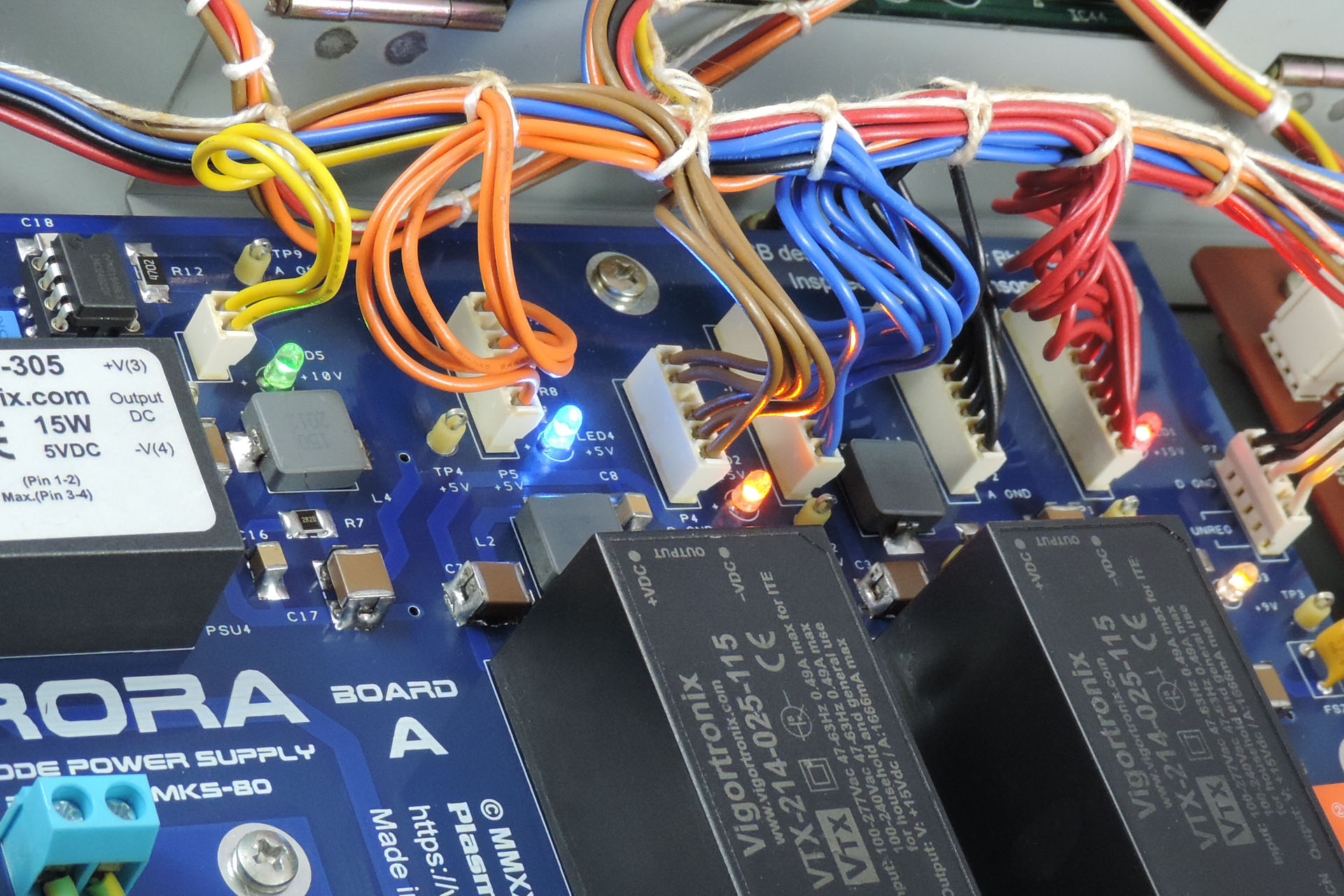
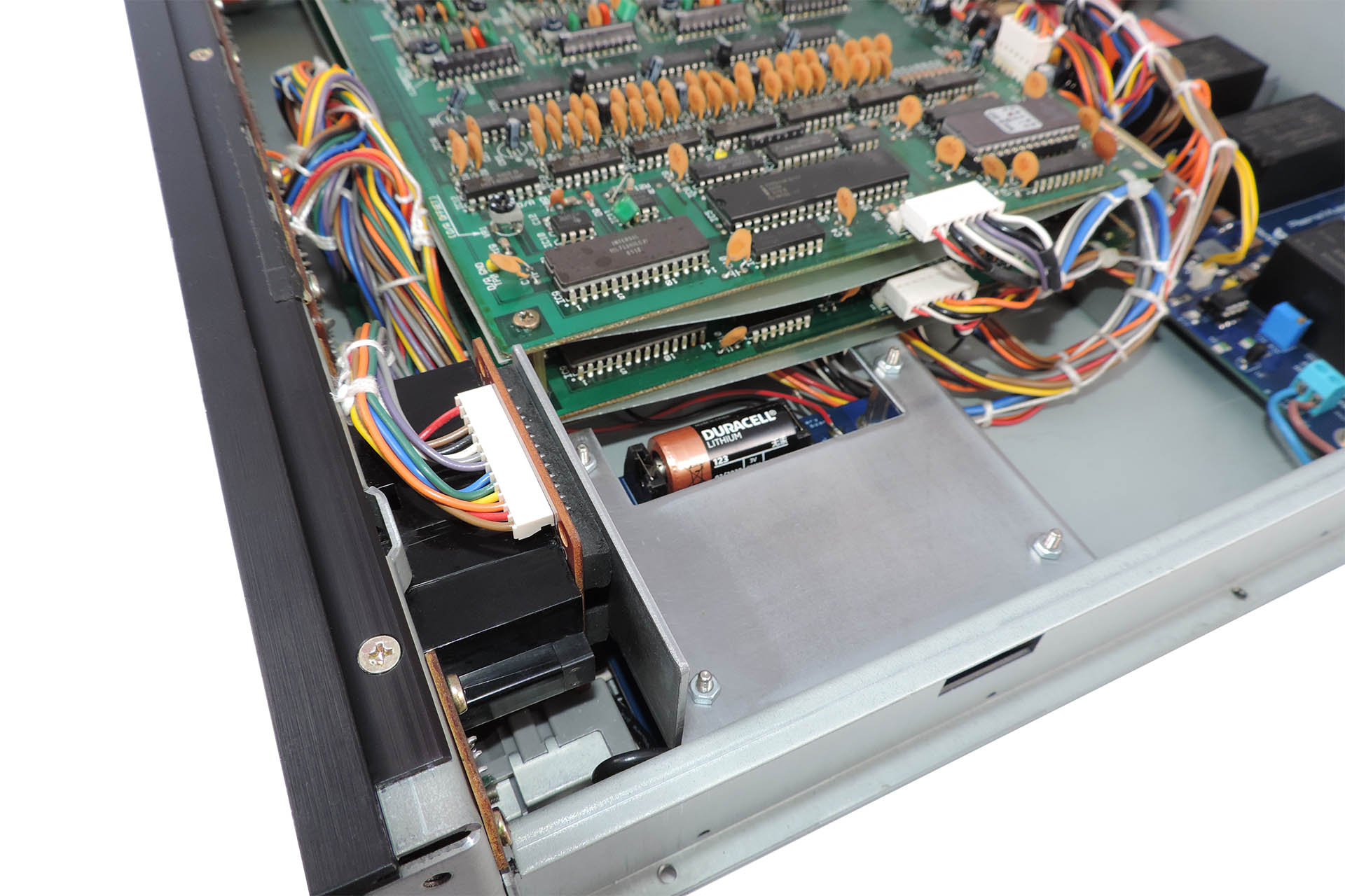
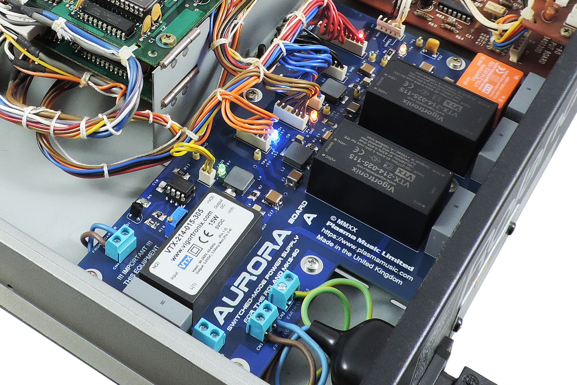
A close-up of Aurora Board A up 'n' running in Jay's MKS-80 Rev. 5.
I love the Roland MKS-80 and know it really well. So if you have one that's in need of repair or perhaps you're even considering one of the upgrades mentioned here, please don't hesitate to get in touch.
In the meantime, you can read about Aurora here and my RE-MKS-80 rack-ears here. Visit my shop to check out prices for my Live-Forever battery mod and installation of Guy Wilkinson's OLED module.
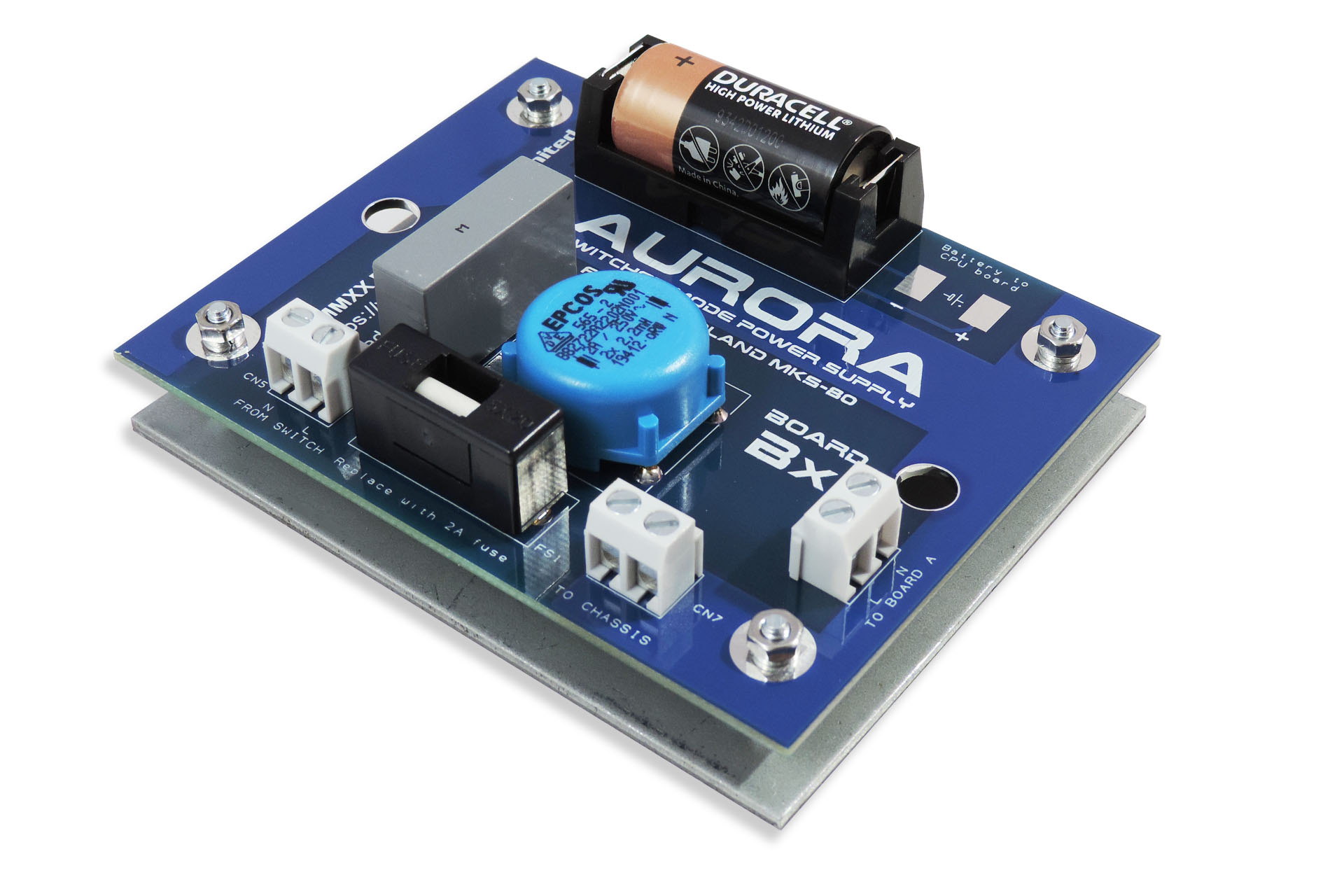
Aurora - the world's first replacement switched-mode power supply for the Roland MKS-80, shown here with the original Board B which was soon upgraded to Board Bx with on-board Live-Forever back-up battery mod.
The Roland MKS-80 is an amazing piece of equipment and a lovely sounding machine. As one of the last all-analogue-voiced synthesisers, I am hopeful that Aurora, a replacement power supply for the Roland MKS-80 will keep all of those gorgeous modules still left on the planet, working just a little longer.
Anyone who has a Roland MKS-80 with a power transformer that’s not native to their region, now has the option to upgrade the power supply in their machine and plug it straight into their mains supply, without the need of going through an external transformer.
If your Roland MKS-80 has a bad power supply or broken transformer, you now have the option to potentially bring it back to life. Also bear in mind that the old FR2 PCBs are now very brittle and prone to dry joints and even cracking.
At the time of writing, some Roland MKS-80s have been operating for thirty-six years! While designed extremely well, the power supplies are stressed systems (as in any machine) and the last thing any MKS-80 owner wants is for the power supply in their machine to go south. IC1 on the original PSU for example, is a M5218L. It's a crucial part of the +5V supply and the 10V reference circuit. If this packs up, the +5V rail could rise to values that could seriously damage your MKS-80 and even make it unrepairable. As time goes on, the likelihood of this happening, only increases. The +/-15V supplies which drive the voice boards, are a little more robustly designed.
Electronics in general doesn’t like heat. Aurora runs much cooler than the equivalent linear power supply.
Over time, your MKS-80 may develop transformer born hum. This can't be 'filtered' out and you're kinda stuck unless you can acquire a replacement transformer. Hey, you're in luck 'cos Aurora doesn't produce any hum!
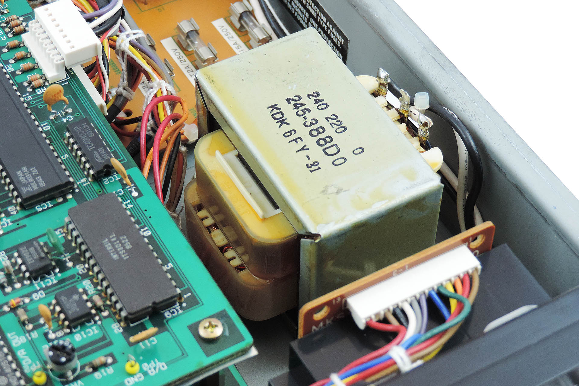
Here's the transformer in a Roland MKS-80. After a couple of decades, they can develop hum.
Originally, Aurora was going to copy the footprint of the original MKS-80 power supply. A single L-shaped board however, would have meant a lot of wastage and potentially necessitate the removal of the front panel to replace the original mains wiring which would have been too short to reach the single PCB.
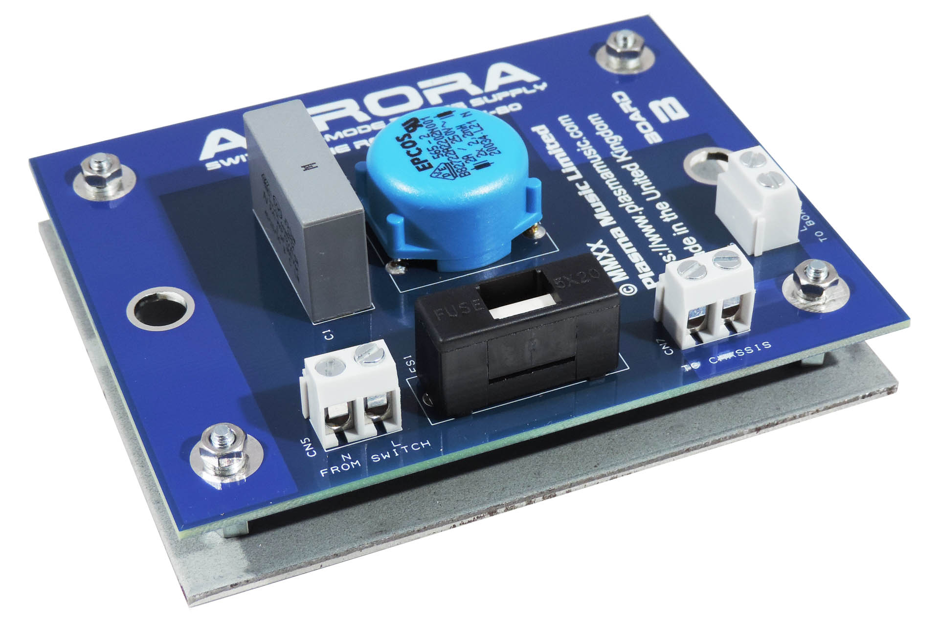
The solution was to split Aurora into two PCBs; Board A being the main part of the power supply and Board B taking care of mains protection and filtering.
Aurora Board B sits my V01 mounting bracket. This occupies the space previously taken by the transformer.
I made use of the reinforcing plate that's underneath the original transformer. The size of board B is the same size as this plate. I simply added four M3 mounting holes and christened it V01, LOL. Whatever, this all provides for a very tidy and cost-effective solution that requires minimal reworking of existing wires, etc.
Aurora's 10V reference source started out as a precision circuit using tight tolerance components and a high-grade op-amp. The results were impressive but later, I changed the design and incorporated a multi-turn trimmer so as to allow for adjustment of the reference which may result from component drift over time.
Adjustment of Aurora's 10V reference, allows for compensation of component drift over time.
Each supply has it's own status LED. I thought this would be a nice addition and in keeping with the original design although unlike the original, Aurora has a different coloured LED for each supply, including the 10V reference.
Also note the test points allowing for easy checking of all voltages.
Aurora has individual power rail status indicators (LEDs) and conveniently placed test points.
So I was going to teach myself Arabic or Mandarin during lock-down 2020 but instead, I kind of decided to design this. It just seemed like a really cool thing to do! 😀 😎
You can read about the development of Aurora Replacement Power Supply for the Roland MKS-80here.
INSTALLING AURORA
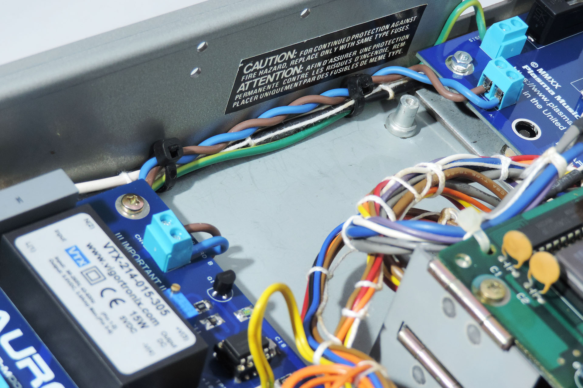
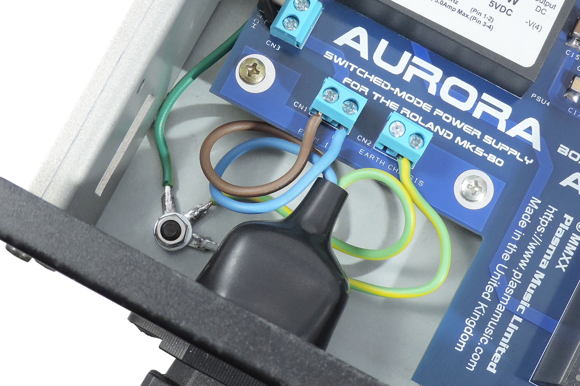
Keep cabling neat and tidy.
Installing the Aurora boards requires a certain degree of knowledge, experience and skill. I therefore insist that the installation be performed by a suitably qualified technician. Aurora is a power supply that converts mains voltage to several DC voltages that your machine requires. Safety is paramount and although fully tested prior to shipping, I strongly recommend that you test Aurora outside of your machine prior to installation. Since there is mains voltage on both boards, care should be taken that the boards are lifted clear of any work surface during such testing, using for example, PCB stand-offs (spacers).
Removing the original power supply including the transformer also requires a certain degree of knowledge, experience and skill. Remember that these machines are over thirty years to over thirty-five years old.
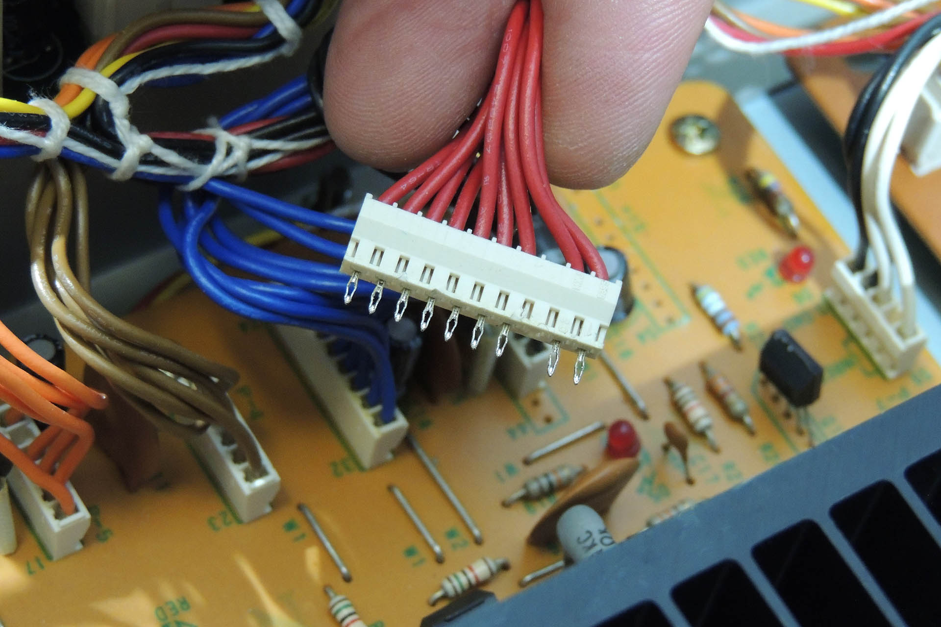
The voltage distribution headers for example, are soldered to the board. The pins on the headers are not conventional straight pins. They're arrowheads and have a tight fit. Once you're confident that you've removed all of the solder, gently prize them off the board (GENTLY). I suggest that you wiggle the connector from the component side while observing the underneath so as to ensure that all pins are indeed free.
+15 V header on MKS-80 power supply showing hollow 'arrowhead' pins.
Don't simply cut the wires to the transformer and the terminals on the original power supply board. Instead, try to unwrap so as to preserve the original length of wire. You may trim some of these later but you don't want to be left short!
Require tools and equipment are as follows:
Temperature controlled soldering station (e.g. Weller WE1010)
Temperature controlled de-soldering station (e.g. Duratool D00672)
Small wire cutters
Small pointed pliers
Adjustable cable strippers
Set of cross-head screwdrivers
Small flat-head screwdriver
Set of box-spanners (metric)
Tweezers
Digital multi-meter (DMM)
PLEASE don't use a plumber's or electrician's soldering iron and please don't use a manual solder pump. You'll just wreck things. In fact, if you're thinking of using that kind of equipment, you shouldn't be operating on your MKS-80, let alone installing Aurora!
Finally Aurora is up and running... beautifully.
A few hints on workflow:
Do NOTrush it! Take your time.
Check and double check your work after each stage.
Do not rely on the status LEDs as indicators of required voltages. Use the test points to measure the voltages with a DMM.
When removing screws and nuts from your MKS-80, use a 'gently, gently' approach. You really don't want studs to loosen or threading to shear.
Do NOTover-tighten screws and nuts. You're dropping a replacement power supply into a vintage synth module and not building a spaceship that's destined for the outer planets!
The 10V reference has been set by me using a regularly calibrated DMM. Please do not mess with it!!!!!
Note the orientation of the headers before you remove them. It's actually not too important other than to keep things tidy except... for P7. Unlike the other headers which each carry a single supply, P7 carries the 9V supply and a digital ground, to the programmer (MPG-80) port via the output board. It's VERY important that this connector's original orientation is maintained.
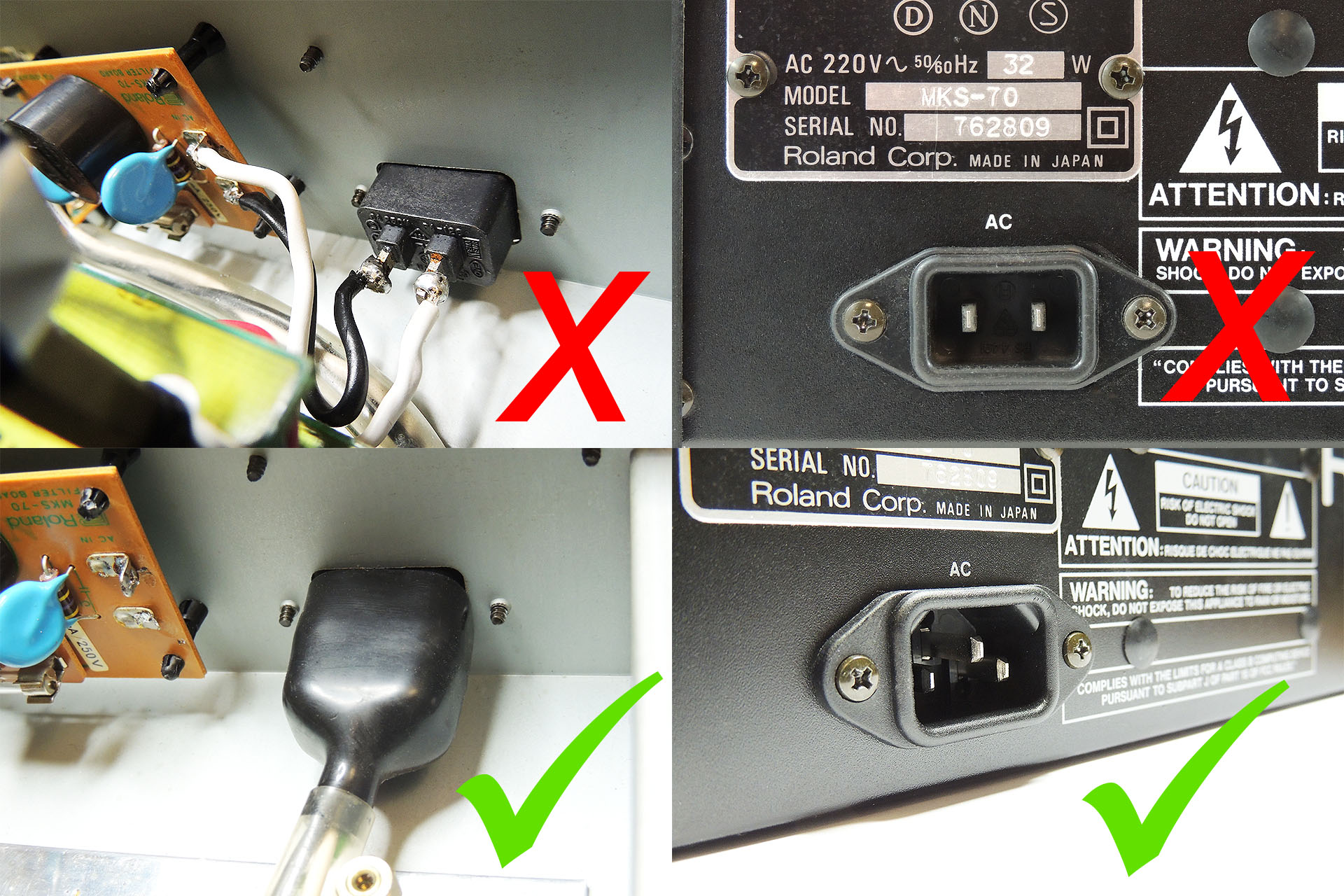
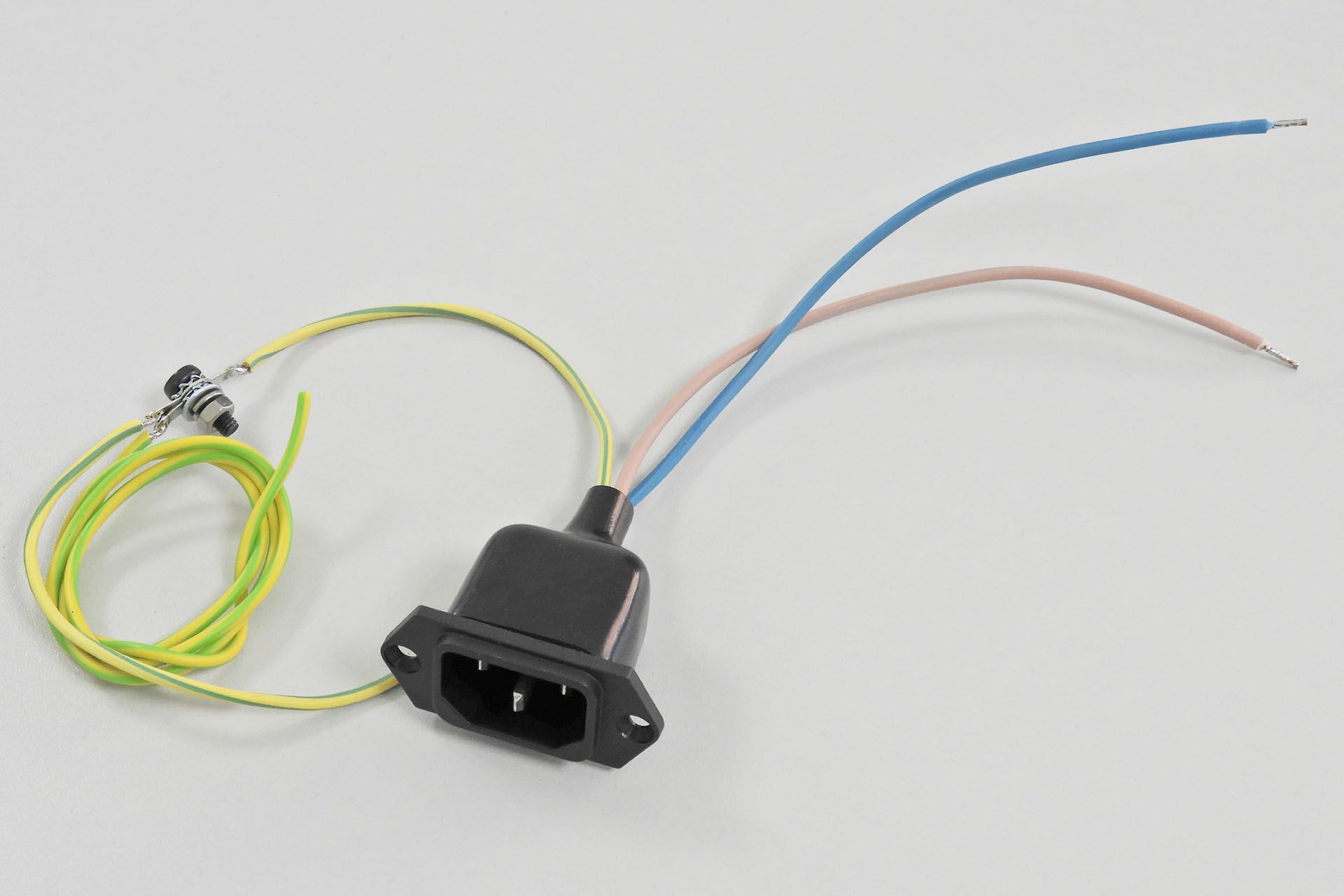
Your MKS-80 MUST BE EARTHED. If you have a 2-pin IEC C10 mains socket, you must replace it with a 3-pin IEC C14 socket. The earth pin should be connected to the MKS-80 chassis. There's a hole in the lower case in between the mains socket and the side of the MKS-80 chassis which will take a M4 screw. DO IT!!!! Aurora board B must also be connected to this point.
It is paramount that if fitted, a 2-pin IEC C10 mains socket be replaced with a 3-pin IEC C14 mains socket and that the chassis and the P0004 are connected to earth.
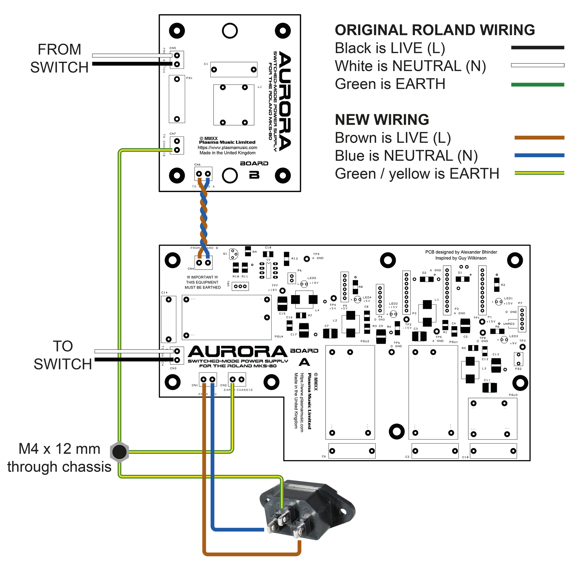
Here's a wiring diagram showing how the two Aurora boards are connected to each other, the mains input, the switch and earth / chassis. Also illustrated is the use of existing (original) wiring as well as some new wiring.
It's really quite straight-forward. You just need to take your time and remember that you're working on a vintage synth module.If your MKS-80 has a 2-pin IEC C10 mains input socket, then you MUST replace it with a 3-pin (C14) IEC socket and connect earths as shown. Also note the insulation boot over the C14 connector.The earth bonding kit for the MKS-80 includes everything you need to safely connect Aurora and your MKS-80 to the mains.
Aurora worked out perfectly. With overrated Vigortronix converters, there's a lot of headroom for the MKS-80 and on top of that, things don't get hot. The carefully designed filters on the back of each converter ensure that Aurora is dead quiet. These are important and you simply won't find them in a commercially available off-the-shelf power supply. Aurora retains a vintage feel with it's through-hole LEDs and fits perfectly into the space left after the original transformer and power supply re removed. No hum, no worries about collapsing supplies, a much lighter MKS-80 and everything's running nice 'n' cool. 😎
It's a common misconception that filters on switched-mode power supplies are there to prevent noise going into the host. The filters actually inhibit noise from the host going into the power and thus, being redistributed.
UPDATE - 7th October 2020
Since August's flood, I've had to move ops back home, temporarily. It's very cramped, things are taking longer (it took me two days to find my oscilloscope) but Julie my wife, is amazingly patient and understanding and a big support during this challenging time.
I currently have three MKS-80s in for Aurora and OLED module upgrades. Two of them have already been done but the fourth (a Rev 4 at the back), has a dead voice which I need to fix before I do anything else.
MKS-80 heaven; two Rev 5s and a Rev 4 (ex Trevor Horn), in for Aurora and OLED upgrades.
UPDATE - 2nd December 2020
So the past few months has seen more than a few Aurora sales and installations. Many customers whose units I've had in, have asked if I could also install my Live Forever memory back-up battery mod and it got me thinking.
Aurora has two boards. Board B comprises mains protection and filtering so, not a lot. With a little nudging, I was able to fit a CR123a battery holder on to the PCB and so Aurora Bx Board was born! Read more about it here.
Aurora Board Bx with on-board back-up battery mod, is now available.
UPDATE - 24th December 2020
Aurora installation instructions are now available in German.
Die Installationsanleitung für Aurora ist jetzt in deutscher Sprache verfügbar.
UPDATE - 24th April 2021
Aurora is now offered with the optional V06 data cartridge re-enforcement bracket. Such a cool solution to a problem that many Roland MKS-80 owners will be familiar with, the V06 basically strengthens an undamaged cartridge slot and reinforces a broken one by putting 2mm of solid steel behind it!
V06 bracket for Roland MKS-80 broken data cartridge slot assembly.
Existing Aurora customers take note; once your Roland MKS-80 is open, V06 can be installed in a few minutes, with just a M3 (5.5mm) nut-runner.
Here are a few pictures of customers' own installations.
I'm deeply concerned about the environment and the exploitation of labour and so I always use local manufacturers in preference to the Far East, with the following in mind:
I can be confident that workers are treated fairly and earn a proper wage.
I can be confident of the standard of quality of each item that is delivered to me.
Communication is important and using local manufacturers, all correspondence is quick and understandable.
I believe in supporting the local economy.
I can be confident that the disposal of manufacturing waste is managed properly and in accordance with national and EU law.
Using local manufacturers isn’t the cheapest option but the above points are important to me. I hope that they’re important to you too.
Please don't hesitate to contact me if you have any questions regarding the Aurora Replacement Power Supply for the Roland MKS-80 or, if you want to buy Aurora or book in your MKS-80 to have it fitted, please check out my store.
Inspired by the great work of Guy Wilkinson from supersynthprojects.com on his P0004 switched-mode power supply upgrade for the Roland Super-JX, I decided to have a go at designing a similar Roland MKS-80 power supply upgrade. As it turned out, Guy helped a lot. After all, he's done this kind of thing before!
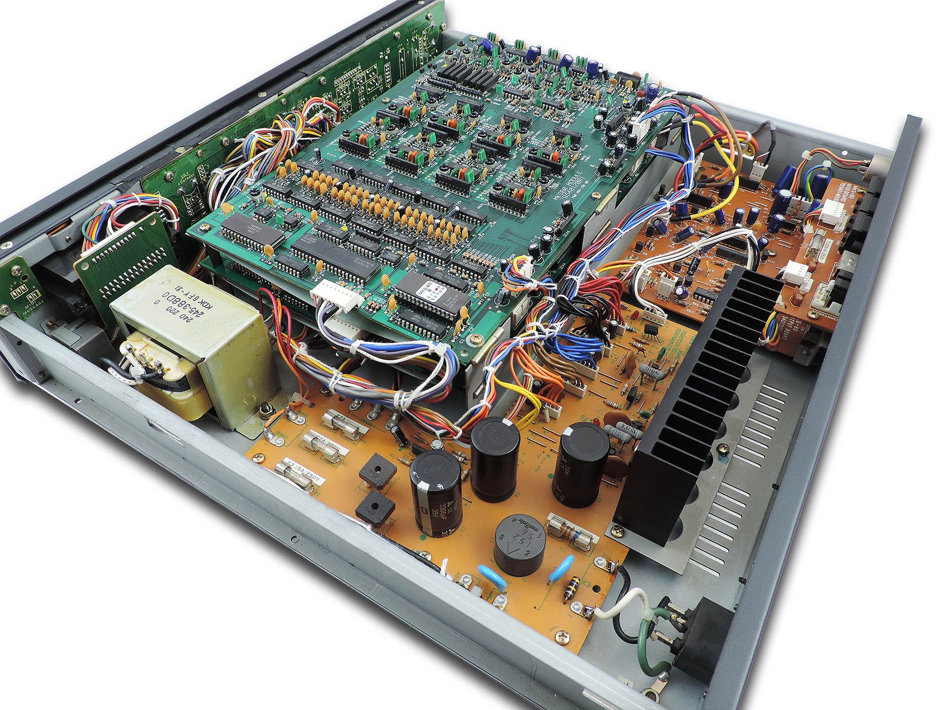
Inside the Roland MKS-80. This was truly amazing technology for the time.
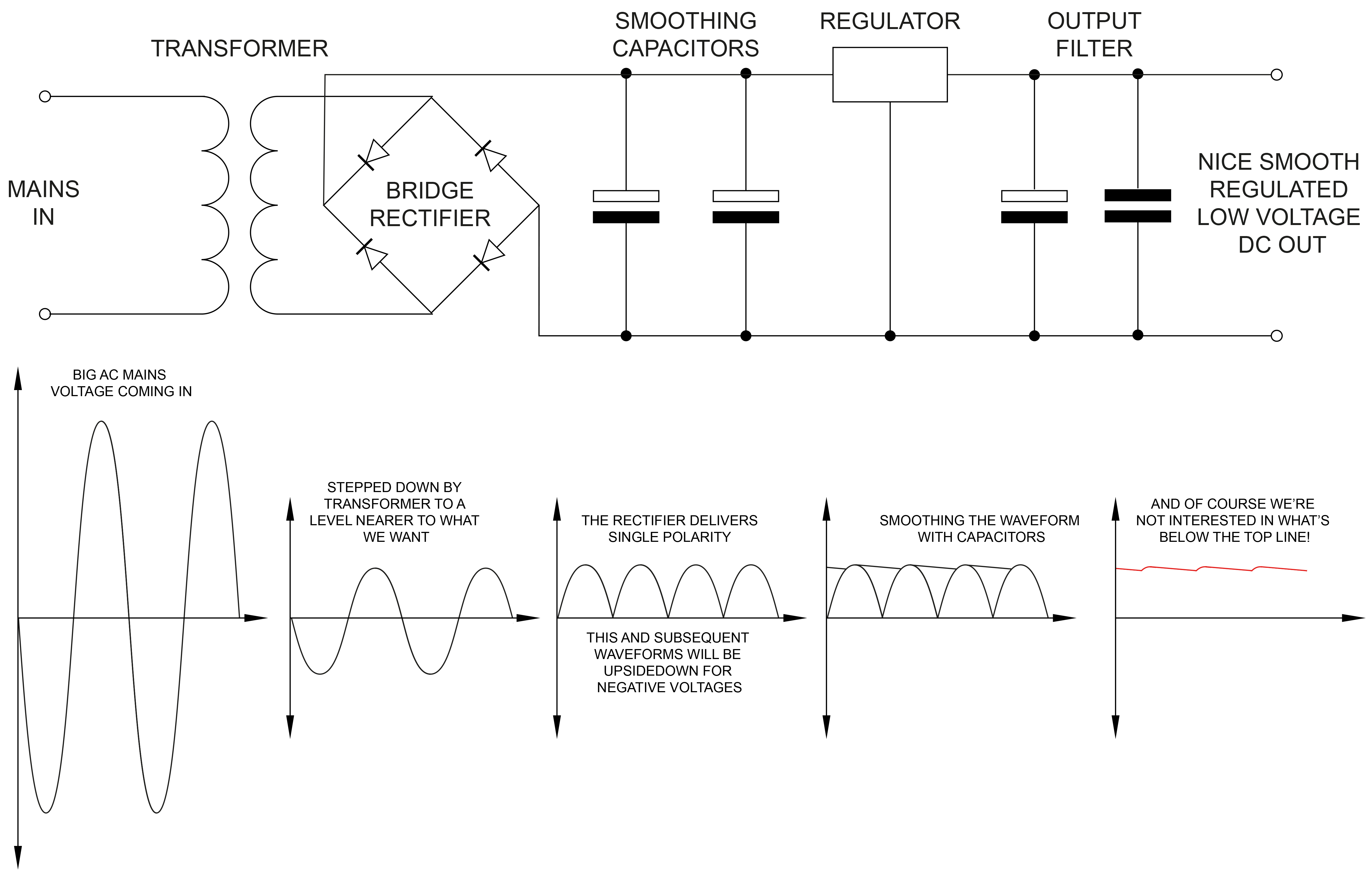
So give me a little space here and allow me to explain the fundamentals of just how a conventional style 'linear' power supplies works...
Firstly, what is a power supply? A power supply is a collection of components assembled to convert a domestic high voltage AC supply to one or several low voltage DC supplies suitable for powering electronic components.
Mains voltage goes into the unit. Although always AC (alternating current in the form of a sine wave), the value of the voltage varies across the world from 240 V in the UK and Australia for example, to 220V in Europe, 115V in USA , Canada and other regions and 100 V in some other places. A transformer is used to ‘step down’ the mains voltage, to something close to what is needed to power the internal electronics. A transformer will often have a couple of 'secondary' windings which produce two or more independent low-voltage supplies.
Here's the transformer in a Roland MKS-80.
In the MKS-80, you're aiming to get a few more volts than +/-15 V for the analogue electronics and +5 V for the digital. Then you might need a little something for say, a remote programmer. In older synths, you’ll also need a reference voltage for the VCOs, for example. In the MKS-80, this is 10 V and needs to be very accurate. It was also quite common to generate other voltages, sometimes complimentary. In the MKS-70 for example, +/-5.6 V are produced on the CPU-board and in the MKS-80, each voice-board has a small circuit which produces +/-7.3 V. These voltages were derived from main supply lines such as +/-15 V from the power supply.
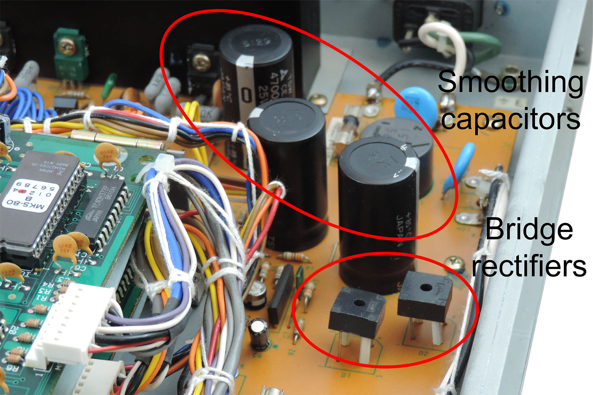
After the transformer, the voltages are still AC meaning that they’re still in a sinusoidal form swinging between positive and negative at either 50 or 60 Hertz (again, depending on where you are in the world). You need to ‘rectify’ these AC voltages which is the first stage to approximating towards DC voltages of a single polarity (plus or minus) and then you need to smooth out the result, with big capacitors.
Finally, you need to ‘regulate’ the voltages. The regulator stage performs two jobs; the first is to deliver the actual voltage required. The input voltage to the regulator will be a few volts more than what comes out from the other end. The regulator 'absorbs' the difference between the input and the output voltages and dissipates this as heat. The second job of the regulator is to maintain the required voltage as the demand for current varies.
So, you normally have one big transformer with perhaps a couple of secondary windings to bring things down. After the transformer, you'll have a couple of rectifiers and then one regulator (and associated filter circuitry) for each supply.
Linear power supply basics
It doesn't stop there. You may have noticed that some power supplies are 'larger' than others. Obtaining the desired voltages is one thing but electronics needs current. The product of DC voltage and DC current is 'power'. So more powerful power supplies are... well, bigger!
Still with me? Good!
Modern switched-mode power supplies do exactly the same job but work quite differently and probably the main physical difference is the absence of a transformer. This omission is generally a big space-saver. When however, you’re requiring several independent voltages in the same box and you basically need one AC/DC conversion stage per voltage, things can get a little crowded.
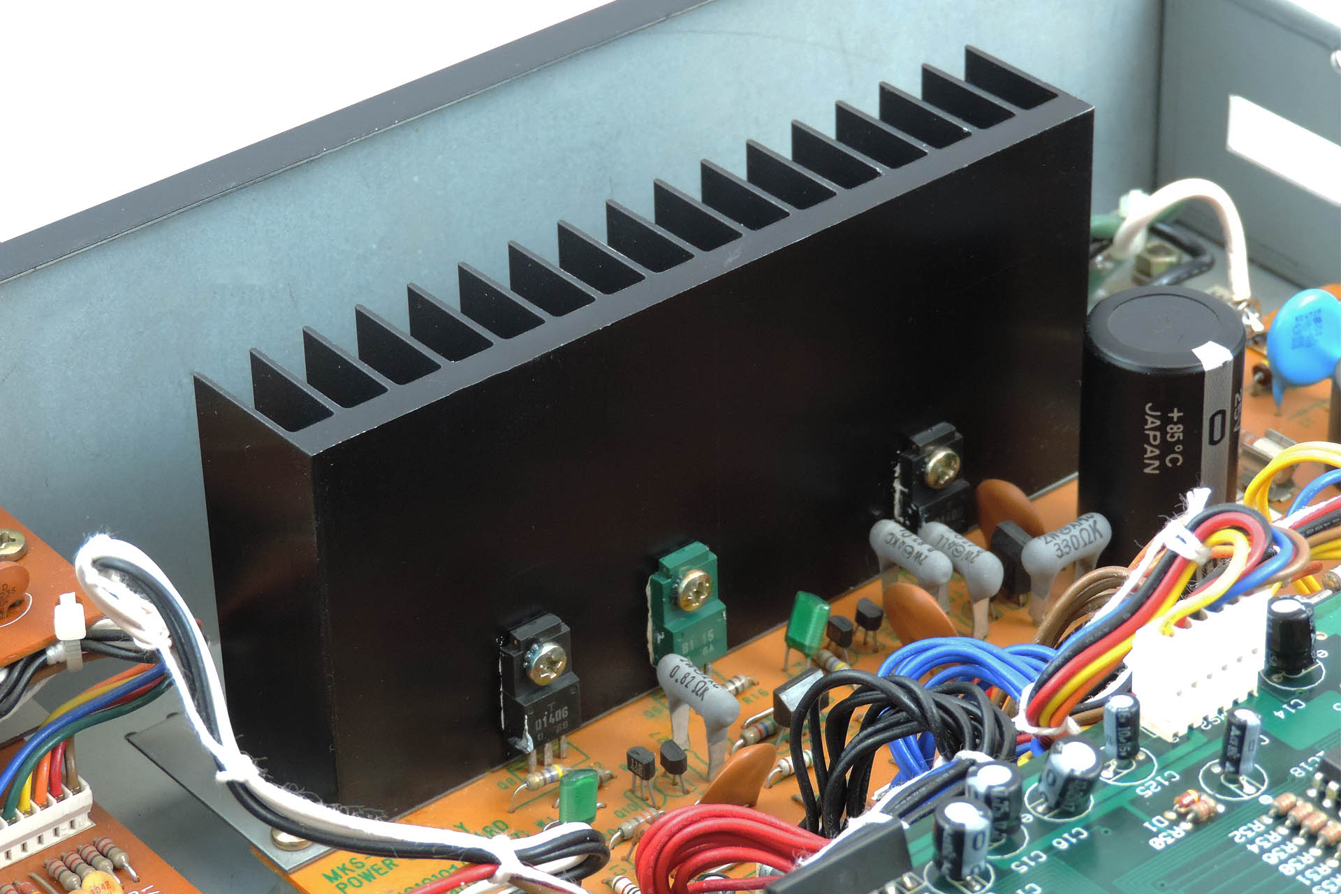
Switched-mode power supplies are considerably more efficient than their equivalent ‘linear’ cousins so generally they don’t get too hot. Some will be familiar with the sometimes, huge amount of heat-sinking present on linear power supplies and the case venting that used to go with them.
And here's the big heat-sink in a Roland MKS-80. Those little devices at the bottom are transistors that form part of the individual regulator circuits and they get particularly hot.
Due to the way they work, switched-mode power supplies can be plugged into virtually any mains supply unlike linear supplies which will require the ‘taps’ on input side of the transformer to be changed… if you’re lucky. Some older equipment would require the whole transformer to be replaced, when changing mains voltage! Oh, those were the days. Since that's virtually impossible all these years later, users of equipment that would have required a transformer change to operate in their region, can only opt for using an 'external' transformer which steps the mains voltage up or down from their region to that which the respective equipment was originally manufactured to operate in. What a drag.
So, if you have a MKS-80 that you acquired from another region and you use an external transformer, fitting an Aurora module into it, will allow you to plug your machine directly into your mains supply. 😎
So truth be known, both linear and switched-mode power supplies have their respective challenges and if not designed properly, can cause undesired side-effects, compromised performance or reduced life expectancy.
In a linear power supply, initial conversion of AC to (a type of) DC is performed by rectifiers, the output of which is 'smoothed' by large capacitors. If not chosen carefully, smoothing might be compromised thereby producing hum. Large capacitors are expensive and take up precious space and over time, the dielectric material inside them deteriorates, thereby reducing their effectiveness. Discrete or comprised linear regulators are very inefficient and can require considerable heatsinking, again increasing cost and demanding even more space. Apart from being a considerable lump of iron and wound copper, transformers generate electromagnetic fields which are seriously not wanted in audio equipment.
Switched-mode power supplies also have their issues. If designed like Aurora which comprises discrete AC / DC converters, issues such as switching noise are greatly reduced. Due to the nature of operation, there is no hum. Neither are there large capacitors that will over time, deteriorate. On the backend of Aurora’s AC / DC converters are additional filers to virtually remove further noise. And of course as has been previously mentioned, the efficiency of switched-mode supplies means that there is no requirement for huge heatsinking.
A bit of Aurora board A in early design. Careful attention has to be given to the physical layout of the filter components in a switched-mode power supply.
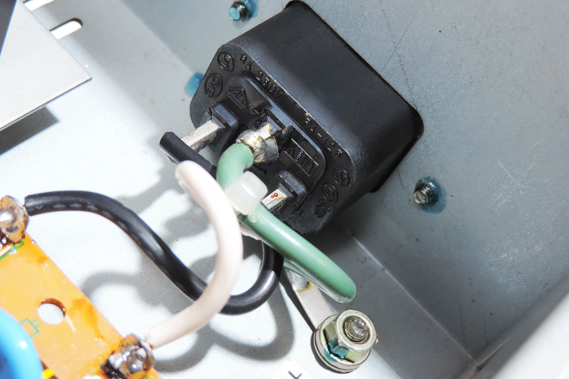
Since Roland launched the MKS-80 in 1984, electrical safety standards have changed considerably and it's important that anything designed today, which is to be made available to the general public, complies with modern regulations. In fact, the decision to make something like Aurora, which potentially can be fitted by 'anyone' was the hardest. On the other hand, there are disclaimers! Follow the rules and everyone should be just fine.
You just couldn't get away with this now-a-days (thank goodness).
EARTHING ISN'T JUST ABOUT SAFETY!!!!
Back in the day, a lot of Roland equipment was shipped with 2-pin IEC C10 power input sockets. Due to the way in which switched-mode power supplies work, specifically the filters, it's important that your MKS-80 is properly earthed. If your MKS-80 has a 2-pin IEC C10 power socket, then you will need to replace it with a 3-pin IEC C14 socket. This item comes as part of my earth bonding kit and can be purchased when you buy Aurora.
A CHANGING WORLD
It’s Spring 2020 and the world has been hit with COVID-19. Countries try to protect their citizens by declaring lock-downs. It’s a depressing time and hundreds of thousands die across the world while many are left alone with the stress of isolation. 2020 is turning into a time for reflection and the global community begins to realise that things might never be the same again, at least for the foreseeable future.
I was lucky, very lucky. I was at home with my lovely wife and one of my daughters who had come back from university, just before the lock-down was announced here in the UK. After a few days, I set up my laptop on the dining room table and came up with a couple of projects, simply to pass the time. One of them was 'Aurora'; a Roland MKS-80 power supply upgrade. I won't bore you with the other ideas.
A QUICK STEP BACK
Just before the lock-down, I had a couple of Roland MKS-70s come in for repair. Having one of these gorgeous synth modules myself, during the repair process, I got quite into the world of Super-JX upgrades. You can read more about that here. Having got to know Guy Wilkinson and also being the proud owner of a Roland MKS-80, one thing led to another.
The first two or three weeks were spent making physical measurements. I needed a board size! Since the massive heat sink would be redundant, I planned to take advantage of that space. Measuring, re-measuring and measuring again... many of the spaces between the mounting studs didn't seem to be exact integers, hence there was always a glimmer of doubt in the back of my head.
The design started off with the idea of using the same board dimensions as the original MKS-80 power supply. I just extended it to take up the area that was occupied by the heat-sink. As things progressed however, it was obvious that this would be an expensive approach and any consideration of commercial supply would be ridiculous. The PCB would require a panel measuring a massive 280mm x 210mm. The board is L-shaped and so, after cutting, that would mean a wastage of over 35%. The board would have been way too expensive to have been viable so annoyingly and after several design revisions, I decided to completely change my approach to using two boards; one, a regular rectangular shape, which would occupy the main area of the original board and heat sink and which is known as Board A and a second board which would accommodate the front-end high-voltage components and which would mount where the original transformer was, known as (you guessed it) Board B.
Checking board size and more importantly, mounting hole alignment, took a long time. I think the paper model pictured, is version 17! Notice that even at this stage, I wasn't confident enough to disconnect the original power supply in my own MKS-80!!!
I must confess that despite having spent the past thirty-five years servicing studio equipment and having been Roland UK's Group Service Manager in the late eighties, I was still very apprehensive about operating on my own lovely MKS-80, which I bought from Roland as a staff purchase and which is in beautiful condition.
Unlike the MKS-70, the headers that distribute power to the CPU-board, voice-boards and output-board in the MKS-80, are grouped by voltage as opposed to destination. This means that all the +15V supplies are on one header, all the -15V supplies on another and so on. Also unlike the MKS-70, the MKS-80 PSU headers are soldered at the power supply end, to the PCB. Another consideration was the classic Roland nice 'n' tidy wiring loom. Ideally I wouldn't want to mess with that so I figured on trying to preserve the relative positions of the header connectors as best as I could.
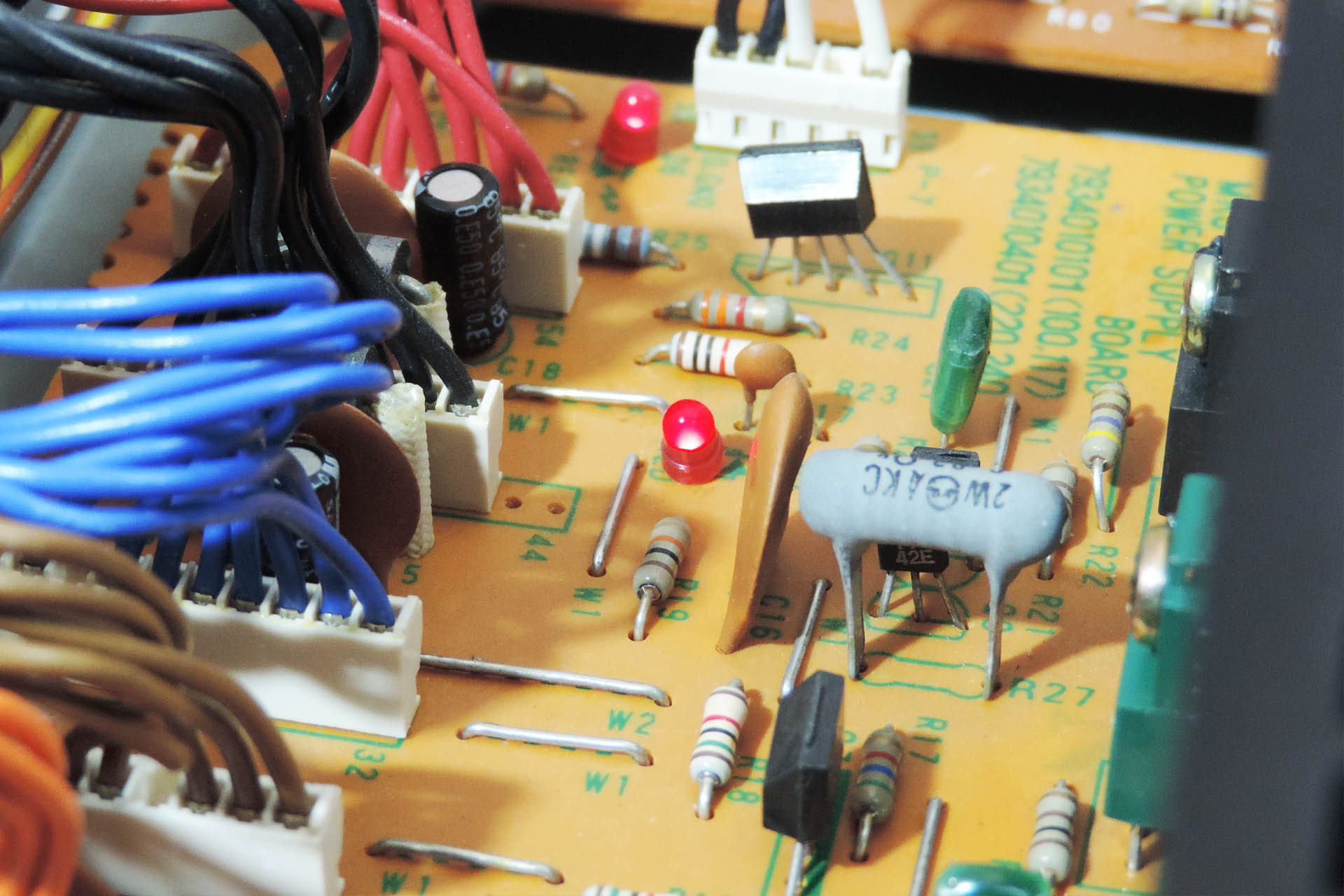
There are two other marked differences between the MKS-80 and MKS-70 power supplies; the MKS-80 has a precision 10V reference source, used for the VCOs. It also has cute little status LEDs which indicate power on the various voltage output lines!
Check out the cute LEDs but also note the soldered power (bus) headers.
Anyway, after some time, I felt as though I'd done enough measuring and so the next stage was to work out the current demand on each line. The unregulated supply wouldn't want too much as it's used to power a MPG-80 programmer / editor, when connected. According to the Roland service notes, the power consumption of the MPG-80 is 0.9W. With on-board 5V regulators, that means that the current drawn is about 180mA.
The 10 V reference source is just that, a reference and so current requirement isn't an issue. That means we're left with +/-15V for the voice boards and +5V for the CPU board.
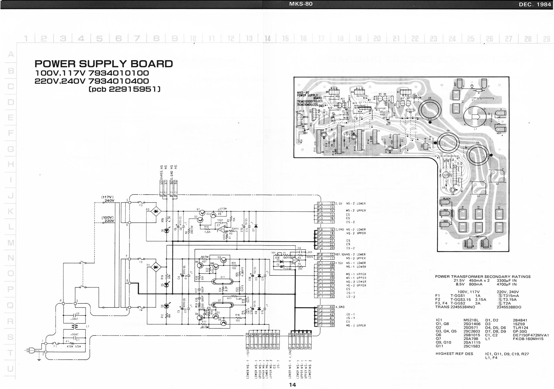
Page 14 from the Roland MKS-80 service notes (second edition, 1985) detailing the power supply.
I so didn't want to start messing around with my MKS-80, lifting components and possibly even cutting tracks, so I decided to try to work out current requirements from the schematics in the Roland service notes. I also used Guy's results from his P0004 MKS-70 power supply project, as the two machines are kind of similar.
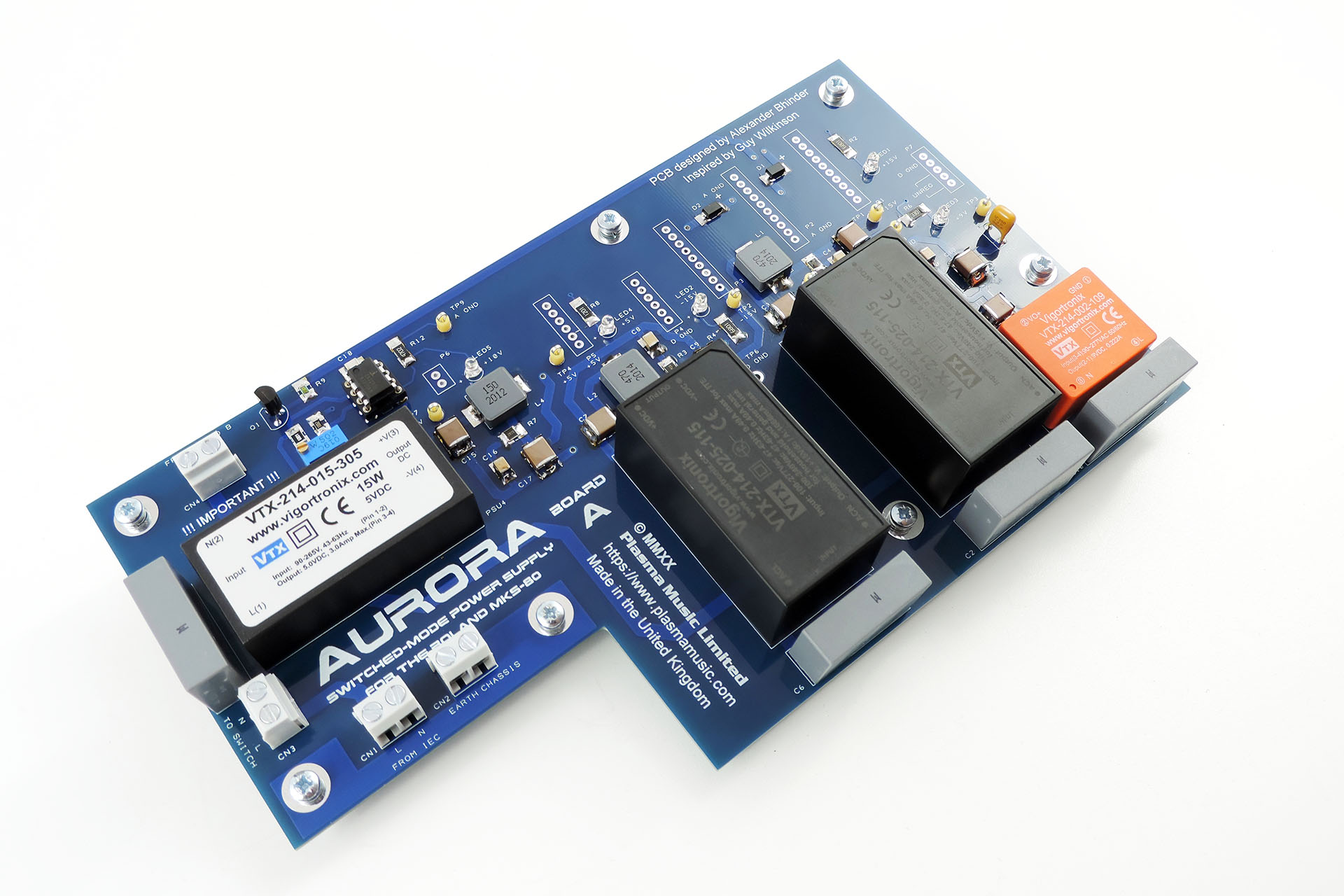
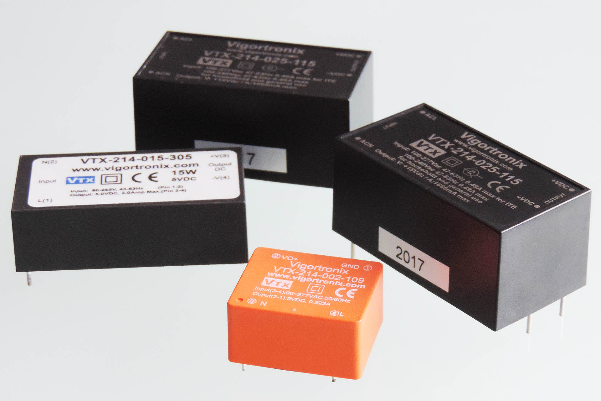
Although more expensive, I went for Vigortronix AC/DC converters. Vigortronix is just down the road from me and I've been using their transformers for many years. Technically, the specifications of the Vigortronix converters seemed much better than the Mean Wells with for example, less leakage.
After having taken my best shot at estimating current requirements, I chose 25W converters for the +/-15V rails and a 15W converter for +5V rail. The power ratings of the converters would theoretically mean that Aurora would run quite cool. For the 'unregulated' supply to the programmer port, I chose the Vigortronix 9V version of the 2W converter which will deliver 222mA.
Vigortronix AC/DC converters, much higher specification than cheaper equivalents and made in the UK.
The 9V supply is being sent outside of the MKS-80, so Roland decided to protect it with a 125mA fuse which resides on the MIDI board. I've gone a step further and dropped in a resettable fuse in line with this supply.
I decided to use through-hole T-1 3 mm LEDs instead of the surface-mount devices that Guy used on his P0004. I figured it would introduce a little retro into something that's so hi-tec in comparison to the original PSU. Back in 1984, I don't remember seeing anything other than red LEDs. This time around, I decided to give each supply, a different colour. Yeah, what the hell? And don't forget the 10 V reference source. Originally I had no intention of putting a LED on this circuit but I eventually caved in. 😎
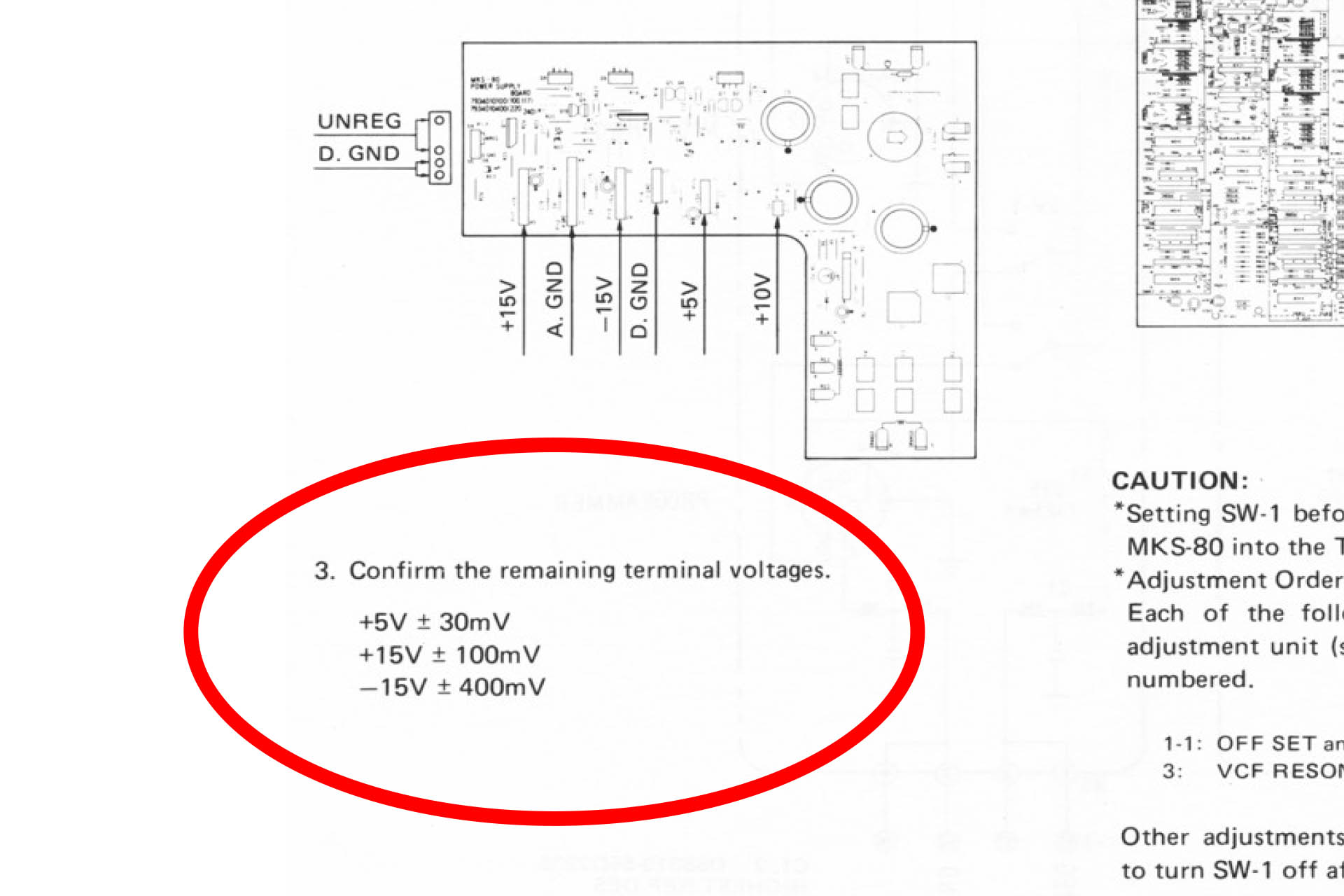
As I worked on the PCB design, I still had some concerns regarding the circuit design. Check out the tolerances of the supplies as specified on page 22 of the original Roland service notes:
Two of those figures are tight, with about 0.6% tolerance on the +5V and +15V lines. Although not impossible to achieve with the type of power supply that's being discussed here, it's not easy and such tight tolerances could be a problem. Typically, AC/DC converters have an accuracy of between 1% and 3% and of course there's a small voltage drop across each all-important filter.
Out of interest, I measured the voltages on my own MKS-80. Here's what I found:
+5V line measured in at +5.01V (10mV ∼ 0.2%.)
+15V line measured in at +15.08V (80mV ∼ 0.53%).
-15V line measured in at -15.10V (100mV ∼ 0.67%).
WOW!!!!! And that's after over thirty-five years! Roland sure could build power supplies.
Well, this realisation was kind of depressing and potentially the whole project could now be in jeopardy and might even end up being a complete and utter waste of time. 🙁
Incidentally, the Roland Jupiter 6 power supply is very similar and has exactly the same tight tolerances.
I carried on carefully studying the service notes. I looked over the schematics many, many times. I just couldn't find any reason for the high level of accuracy specified for the +5V and +15V rails and yet the accuracy for the -15V line was pretty average. The CPU-board should work fine on a little less than (bang-on) 5V. In fact slightly lower would be better. Although the critical 10V reference voltage is initially derived from the +15V rail, the fact that it's adjustable means that not even this would require such a tight tolerance on that supply.
So despite the fact that the thought of blowing up my MKS-80 if I was wrong, was constantly at the back of my mind, I decided to carry on.
The circuit for the Aurora was actually quite simple, to be honest. The PCB layout however, was not. Guy and I communicated almost every day while I was designing the PCB. In fact I only hope I wasn't too much of a pain for him! His extensive knowledge and experience of power supply filter design however, proved invaluable and we both shared a mutual attention to detail. Quite honestly, I couldn't have delivered this project without his help and so I'm actually considering the Aurora, a co-design effort. Thanks, Guy!
UPDATE - 5th SEPTEMBER 2020
Finally Aurora has landed and it's running beautifully.
Ordering prototype PCBs is a slightly nerve-wrecking experience and by the beginning of August, having made several tweaks to the PCB layout, I was waiting for the fourth and final version to be delivered. Then, on 12th August and after a major storm, my studio got seriously flooded. The experience was devastating. You can read about it here. Sod's law; the day after the flood, my final version PCBs arrived. In fact, that week was supposed to be the week that I officially launched Aurora but it all went kinda wrong due to the flood.
Once all my gear was safe and I had a plan in mind on how to move forward, I built a couple of Aurora boards and (somehow amidst all the chaos and my profound feeling of utter devastation) found the courage to drop a set into my own MKS-80 amidst the chaos and devastation of the flood aftermath. What was I thinking?!?!?
Anyway, I couldn't believe it. A bit of good luck for a change. WOW!!!! It all worked. Measuring the supply voltages, everything looked just perfect with +15.00V, -15.07V, +4.97V and +9.01V using the sample converters that Vigortronix sent me. There was no hum on the audio and it was remarkably quite, too. After an hour of being on, the converters were only slightly warm. This was great news.
Over the next few days, I put Aurora through its paces. Like many switched-mode power supplies, Aurora doesn't like being switched on and off in quick succession. That's probably not a good thing to do to your precious MKS-80, anyway. It's not a light-bulb!
Aurora worked out perfectly. With overrated Vigortronix converters, there's a lot of headroom for the MKS-80 and on top of that, things don't get hot. The carefully designed filters on the back of each converter ensure that Aurora is dead quiet. These are important and you simply won't find them in a commercially available off-the-shelf power supply. Aurora retains a vintage feel with it's through-hole LEDs and fits perfectly into the space left after the original transformer and power supply re removed. No hum, no worries about collapsing supplies, a much lighter MKS-80 and everything's running nice 'n' cool.
It's a common misconception that filters on switched-mode power supplies are there to prevent noise going into the host. The filters actually inhibit noise from the host going into the power and thus, being redistributed.
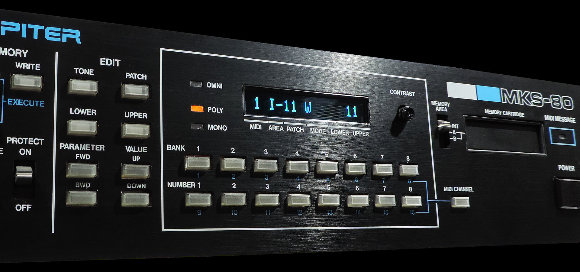
It's really difficult to convey the crisp, sharp and vibrant character of Guy Wilkinson's MKS-80 OLED modules, with a simple photograph.
Okay, so the display on the MKS-80 doesn't really tell you too much but the new OLEDs do look really cool. More importantly, you don't have to worry about the old LCD backlight packing up or the inverter starting to whine. In fact I pulled the coil and the transformer from the CPU board, as they're completely redundant, now. 😎
Anyway... designing Aurora was a challenge but thoroughly enjoyable and I learnt so much. A working modern power supply for the Roland MKS-80. Wow! 🙂 With Aurora now finally working and really well tested, please read my official post here or just buy it here: