 One afternoon in late September 2025, a customer turned up to collect his Marshall JCM-800 combo that I’d serviced. My customers mean everything to me and it’s not unusual for those who turn up at my door, to stay a while. 😊 Anyway, Iain and I really hit it off and after mentioning his software work, I told him about my Gary 7 MIDI kit selector for the Simmons SDS7 idea.
Gary 7 was going to be another one of my software-based ideas which would probably never see light of day but then Iain offered to pop over one afternoon to help get me started with coding for the Raspberry Pi. First, he gave me a short list of various bits ‘n’ pieces I should buy in advance of his visit.
Well, Iain stuck to his promise and sometime in November 2025, he came round to explain how Raspberry Pi stuff worked. We had a fantastic afternoon and I learnt so much. THANKS Iain! 😎
Unfortunately, it was also roundabout this time that my doctor told me that a recent routine blood test had come back with a high PSA level. As it turned out, I was eventually diagnosed with prostate cancer. As you can imagine, the news was quite devastating. On the other hand, life goes on and the only way I could focus on the future was by being with my family and working on stuff that I love… like Gary7.
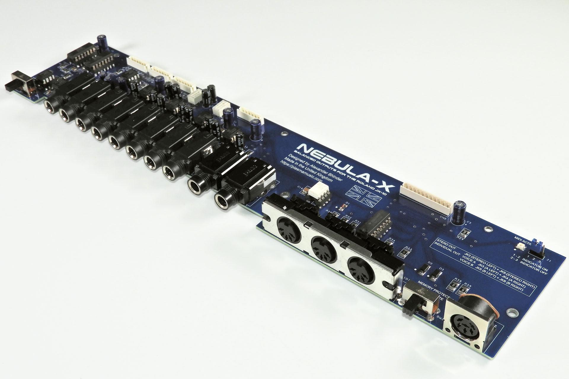
I also had another project that would help keep my mind off things. Nebula-X balanced outputs for the Roland JX-10 had been on my shelf for a couple of years. My third and last revision PCBs had been delivered and I was very keen to get this done too. Hence, my Nebula-X project took priority over Gary 7.
Iain introduced me to the whole Raspberry Pi thing and showed me stuff which, if I had to suss out on my own, would have taken me weeks if not months. More than that, his patience and general way was particularly inspiring. Iain’s a Java programmer specifically but showed me some Python code which kind of pointed towards what I wanted Gary 7 to do. Yes, I know that the firmware used for MIDI is either written in C or C++ but it wasn’t about the language or code. Iain had a way about him and well, gave me the confidence to make a start. It was a kind of Eureka moment, if you like.
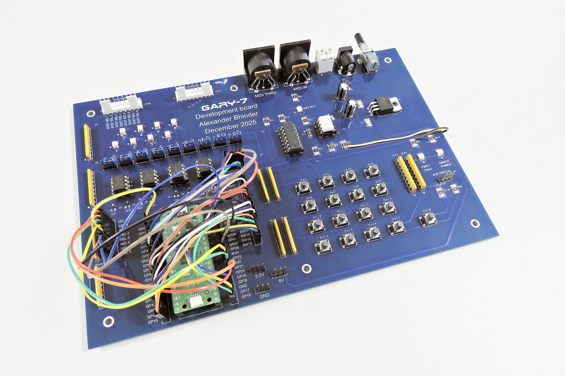
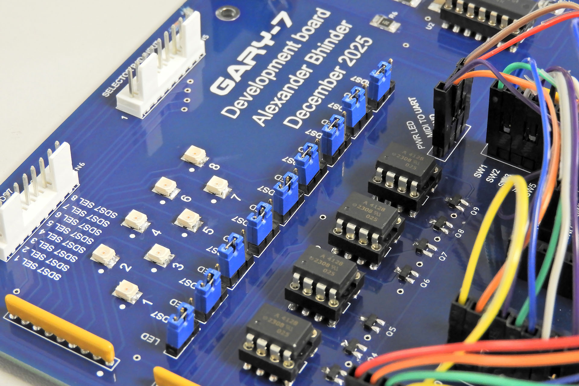
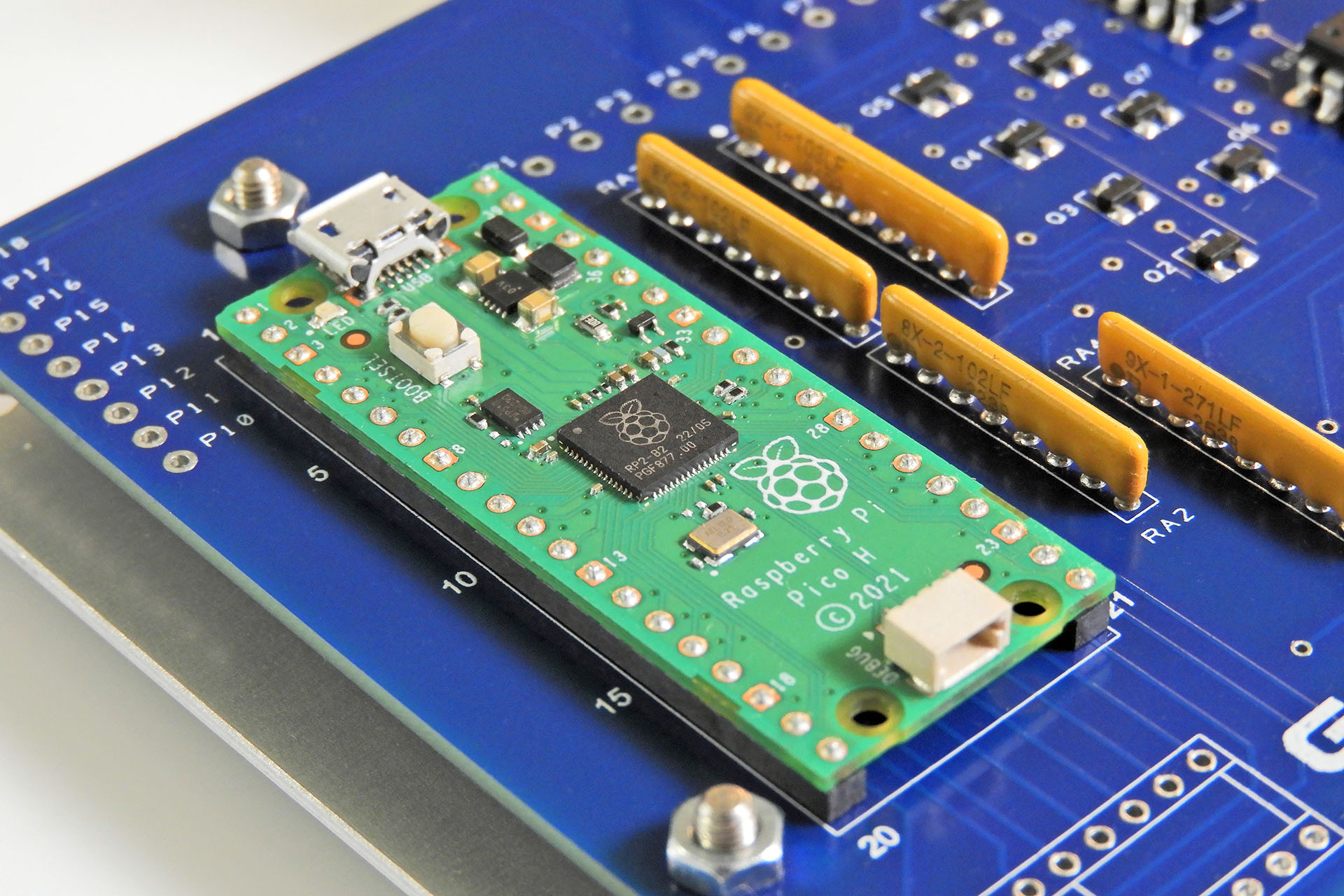
While I toiled with how I was going to approach this whole software thing, I began designing a development board for Gary 7. This was by no means a prototype but simply a board which had a lot of open connections and which would allow me to easily change things if necessary. I believe 'versatility' is the word I'm looking for.
Indeed, although the objectives of this project were quite straight-forward, there was one major aspect of my Gary 7 MIDI kit selector for the Simmons SDS7 in which I had no real experience and that was of course, software.
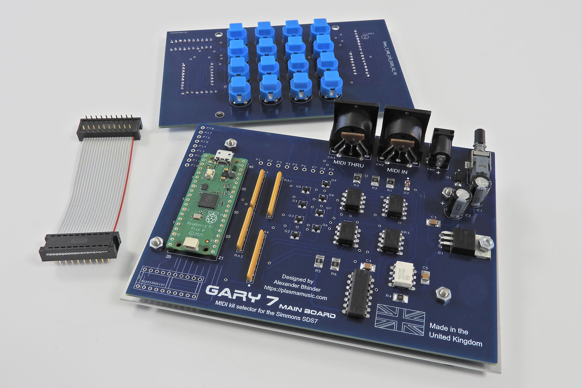
My Gary 7 development board happened quite quickly. Of course, I didn’t use a full Raspberry Pi but chose the much smaller Raspberry Pi Pico. I was soon talking to Iain and other friends about the best way to proceed.
On a side note, with a chunky 7805 regulator, Gary 7 can be powered from an external 9V - 12V DC power supply. 😎 I used a 12V PSU just to check that the 7805 could deal with the voltage drop across it while delivering the current that the board required.
I’ve always been quite critical of AI but this project seemed to be an ideal opportunity to ‘have a go’. It was round about this time that another new friend and I decided to meet up.
As soon as Mike Walden announced his newly designed main-board for the Simmons SDS6, I contacted the customer of a unit that had been brought in to me and subsequently bought the first of Mike's boards. That was almost a year ago. Since then Mike and I have hooked up several times on line but just before Christmas 2025 he kindly agreed to come over to my place to chat Simmons SDS6.
I mentioned Gary 7 to him and that I was considering using AI to develop the software. "Give it a go. See what happens" was his response. With a lot of initial help from Iain and a word of reassurance from Mike, I decided to start where everyone starts and that was with a prompt, a detailed and methodical description of my objectives and the means with which I intended to deliver them. That might sound simple but like most things in life, what you get out of AI is only as good as what you put in.
On a sidenote, if you're interested in Mike's replacement main-board for the Simmons SDS6, you can read more here.
December 2025 was a weird time for me and my family. Nebula-X and Gary 7 were much needed distractions and with the latter, I also immersed myself into the whole AI thing. It only took me two prompts to get something working but boy, did I learn a lot.
After getting the MIDI to SDS7 kit selector lines to work, I decided to push things. With sixteen switches to allow manual kit selection of the SDS7, I introduced a way of setting Gary 7’s MIDI channel with those switches, for example. Of course, it would have been kind of frustrating if Gary 7 didn’t remember the MIDI channel. Hence, the set MIDI channel had to be written to the Pi Pico’s memory. Then I came up with the idea of getting Gary 7 to remember the last kit selection prior to power-down. I referred to this as 'the last command'.
Early tests revealed unreliable memory retention so this had to be addressed and so the memory architecture and management of the Pi Pico were examples of what I learnt from the AI that I was using.
All versions of Gary 7 up to 1.6 were developed with the aid of AI so that was six prompts. I specified that all variables should be listed at the top of the code so tweaking the next three versions of the software was easy and something I could do myself.
By version 1.9, Gary 7 MIDI kit selector for the SDS7 was rocking!
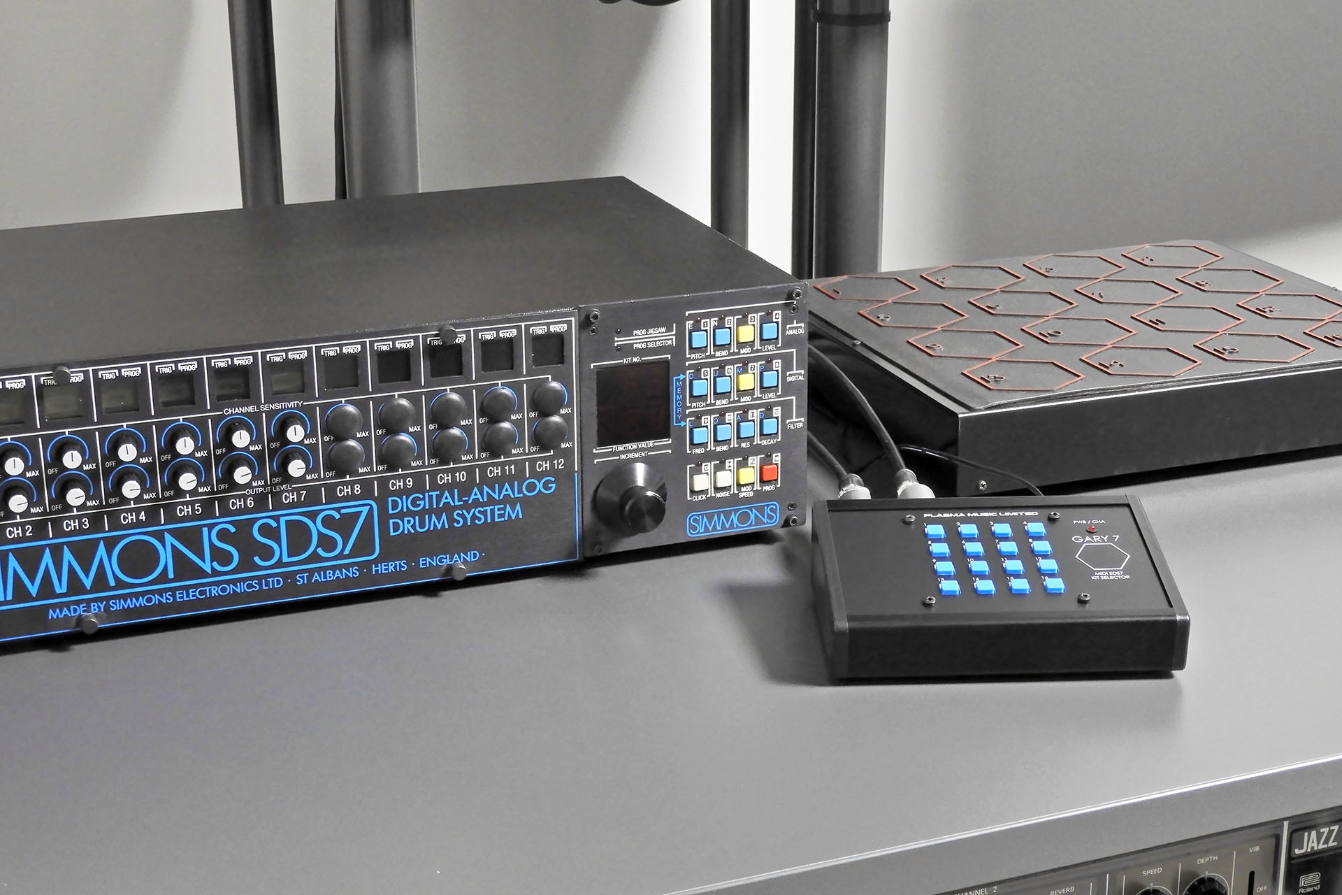
With my cancer prognosis constantly in the back of my mind, getting Gary 7 MIDI kit selector for the Simmons SDS7 working was just so exciting, I just had to record it all. The two videos below show my bench testing.
Before I continue, let's quickly consider the whole kit selector thing of the Simmons SDS7 and the hardware I chose to do this...
The mechanism behind the kit selector of the SDS7 is simple but ingenious. Four signals from the SDS7 are switched to four outputs in a rather clever combination so as to allow for sixteen options. Gary 7 uses optical relays, emulating the zones or ‘pads’ on the Simmons selector pad, thus switching the four signals in the combinations required, to the four outputs.
Now then, questions could be asked like…
“Why have the expense of the opto-isolated relays when I could have just got the Raspberry Pi Pico to generate four signals and switch them accordingly?”
Well, any SDS7 user will be aware that this ol’ girl can be a bit temperamental and I figured that yes, it’ll cost a bit more and yes, things will be slightly more complicated for me but I really wanted to keep SDS7 as isolated as possible. I also wanted to ensure that SDS7 sees exactly what it wants to see on the four returning lines.
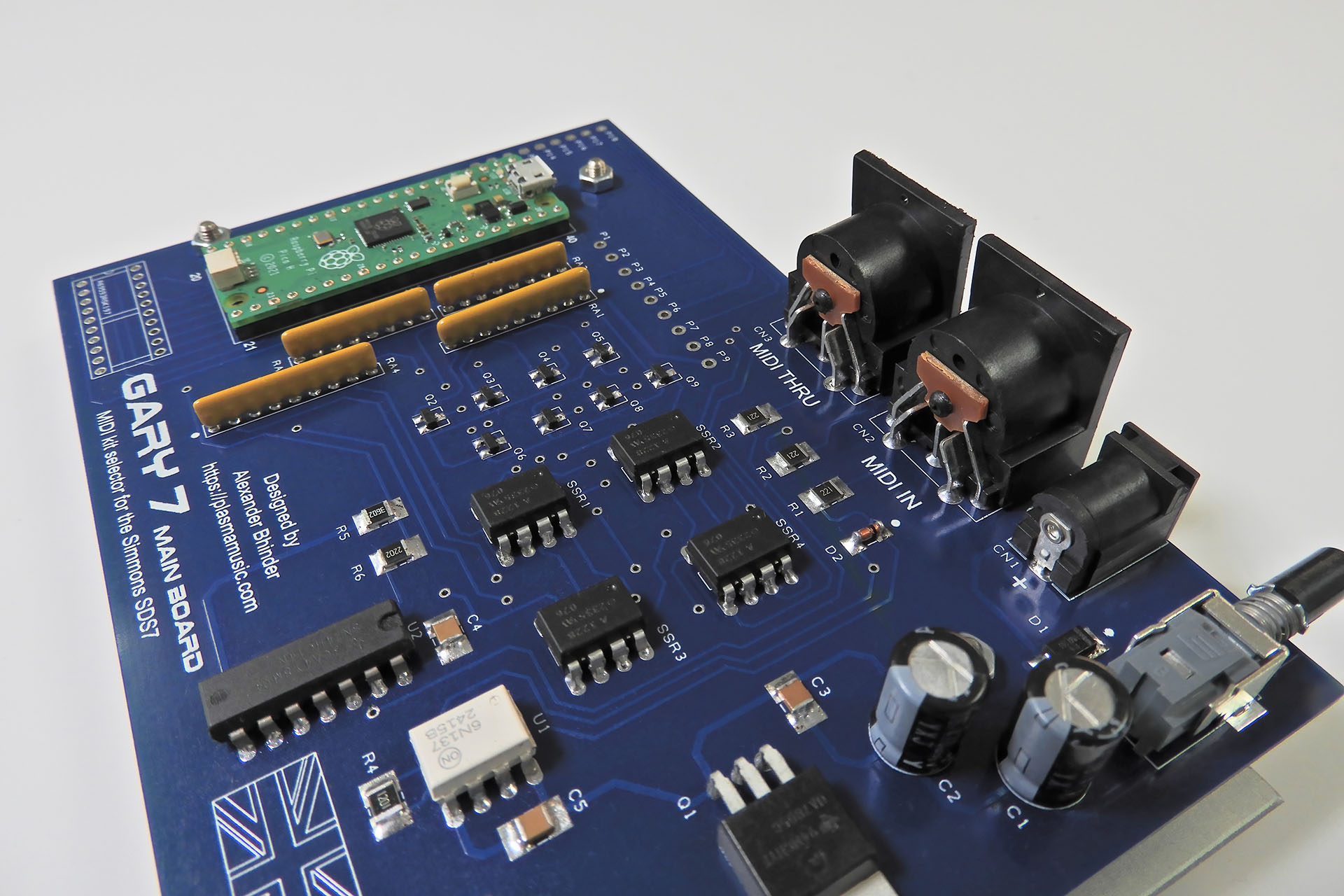
Electromechanical relays would have cost more, potentially drawn more current and perhaps more importantly, they would have been much slower than optical ‘solid state’ devices so the reason to go for SSRs was clear.
The next challenge was to find a suitable enclosure. There wasn’t much point to start designing PCBs if I didn’t know what they were going to go into. To be honest, I had a rough idea of the size of box required so I actually started looking for something back in November 2025, when I first had the idea of Gary.
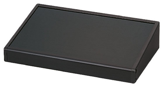 The Takachi CF series of cases, specifically the CF16-11BB consistently came back as my favourite and one of my suppliers seemed to have this in stock so I bought one for prototype purposes. Yes, it was more expensive than I’d have liked but it was small, made from aluminium and readily available.
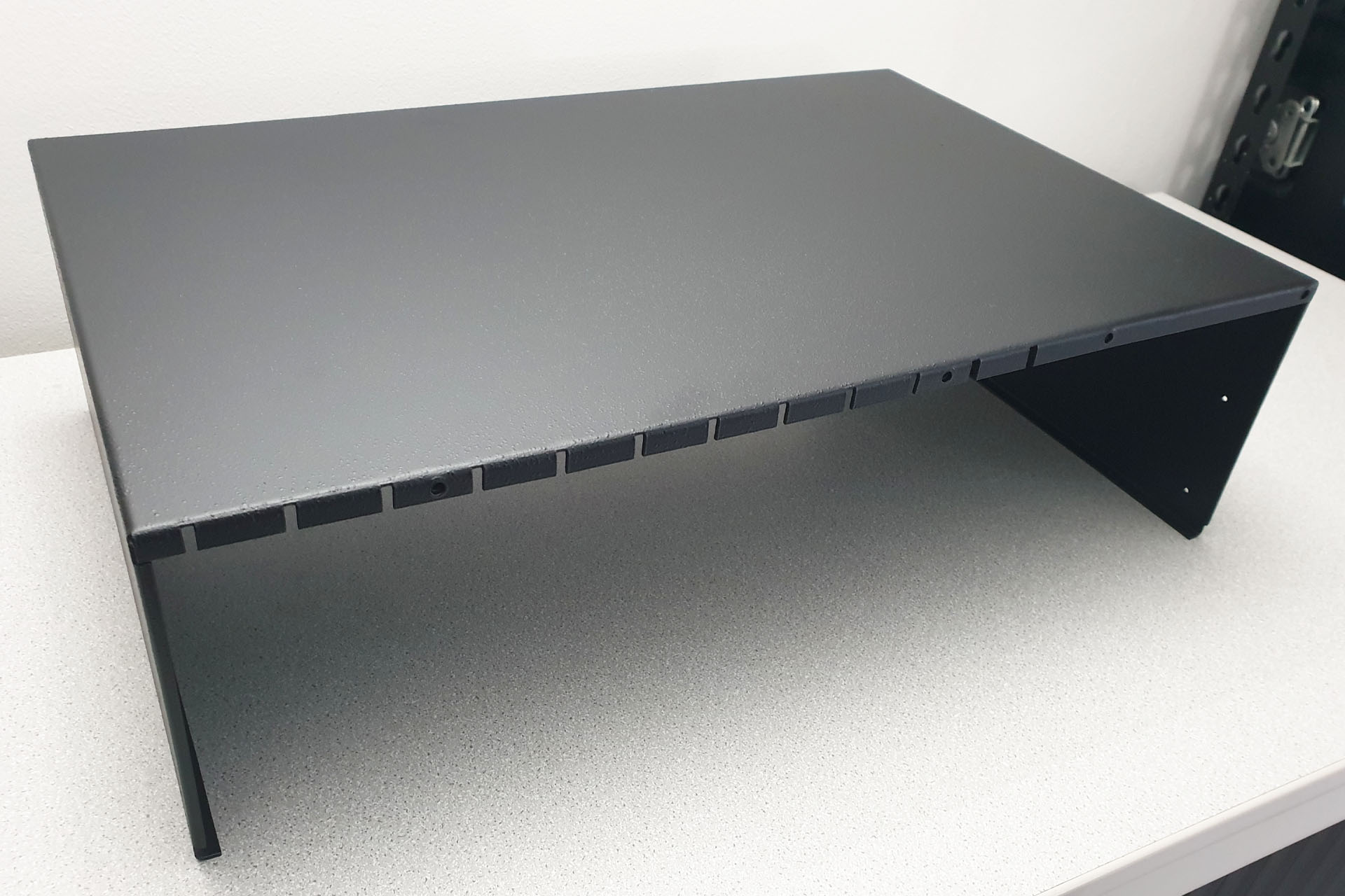
There was however, one very slight problem. The rear of the enclosure had a 10° slant from the vertical axis. To ensure that the rear sockets sat flush with the rear panel, I had to come up with a plan.
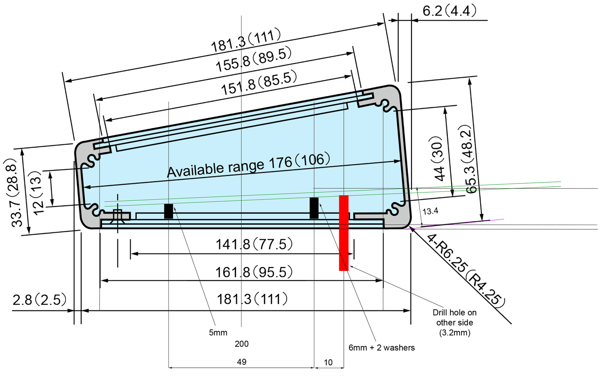
You'll notice in the image above, that my 'plan' was to use slightly higher PCB stand-offs at the rear and slightly lower stand-offs at the front.
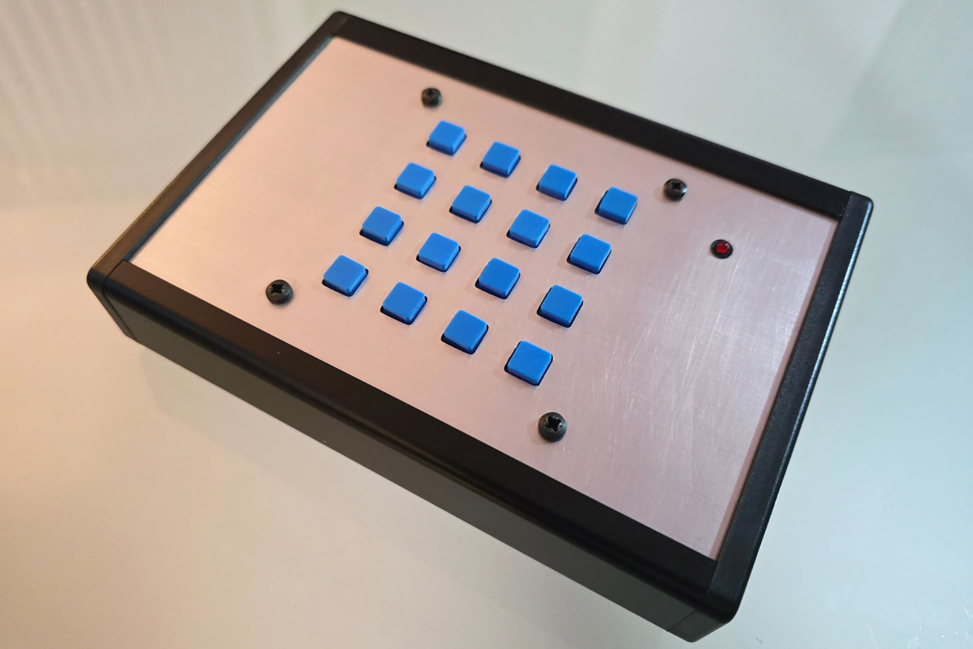
Despite lots of experience and all my best efforts, my first attempt at the Gary 7 enclosure had a couple of errors. The cut-outs for the switches were 1mm too big. I had to scrap the black anodised Takachi panel and get Lenton Engineering to make a new one from just plain aluminium.
The other issue I had was down to the big multi-pin connectors on the rear panel. Basically, they were set too high. You can't see this too well in the image below but on the rear of the chassis mounting sockets, the securing nut butted into the top channel used for the side-screws of the enclosure. Lenton Engineering cut the channel but this wasn't the way to go, long term.
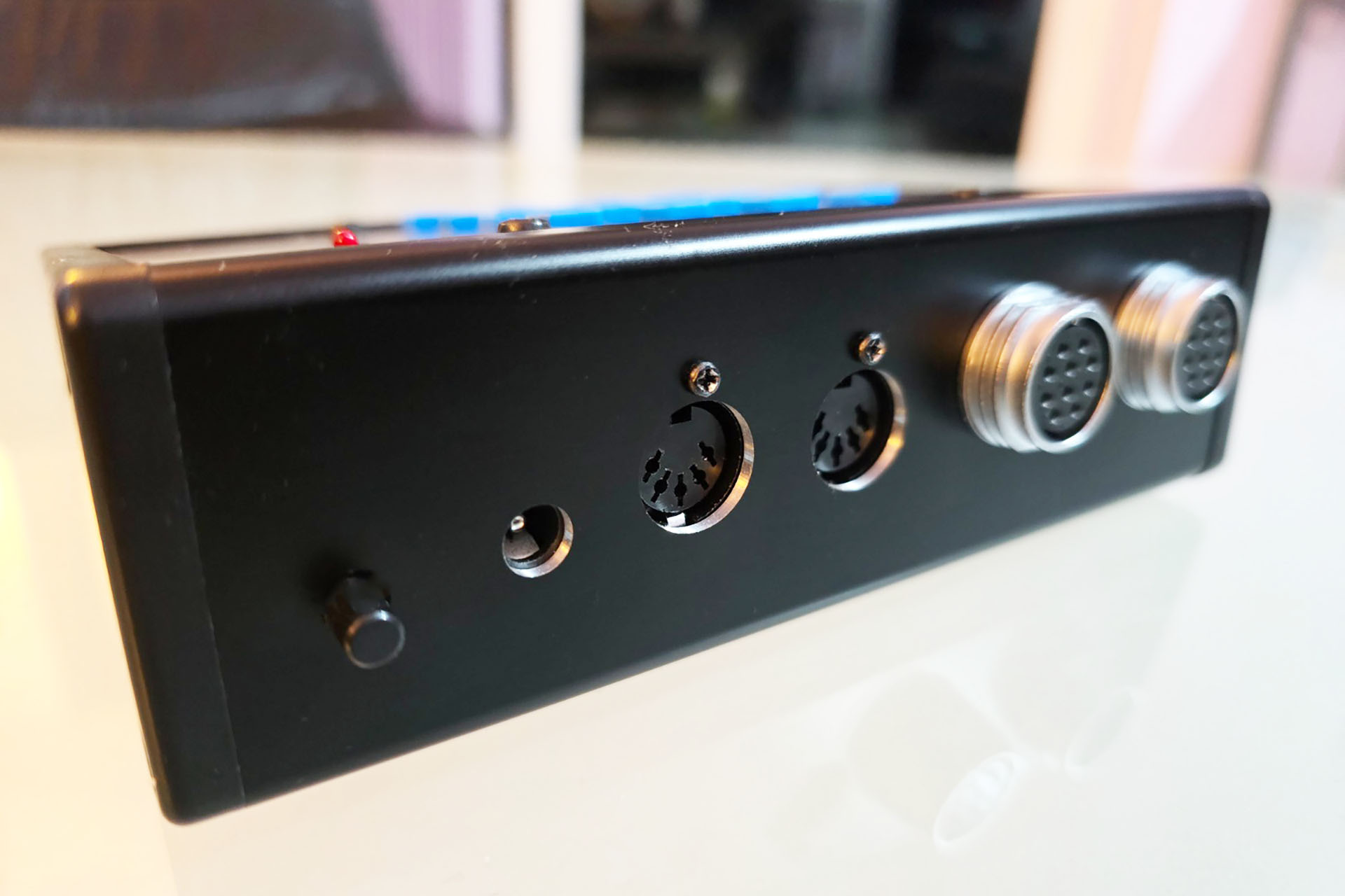
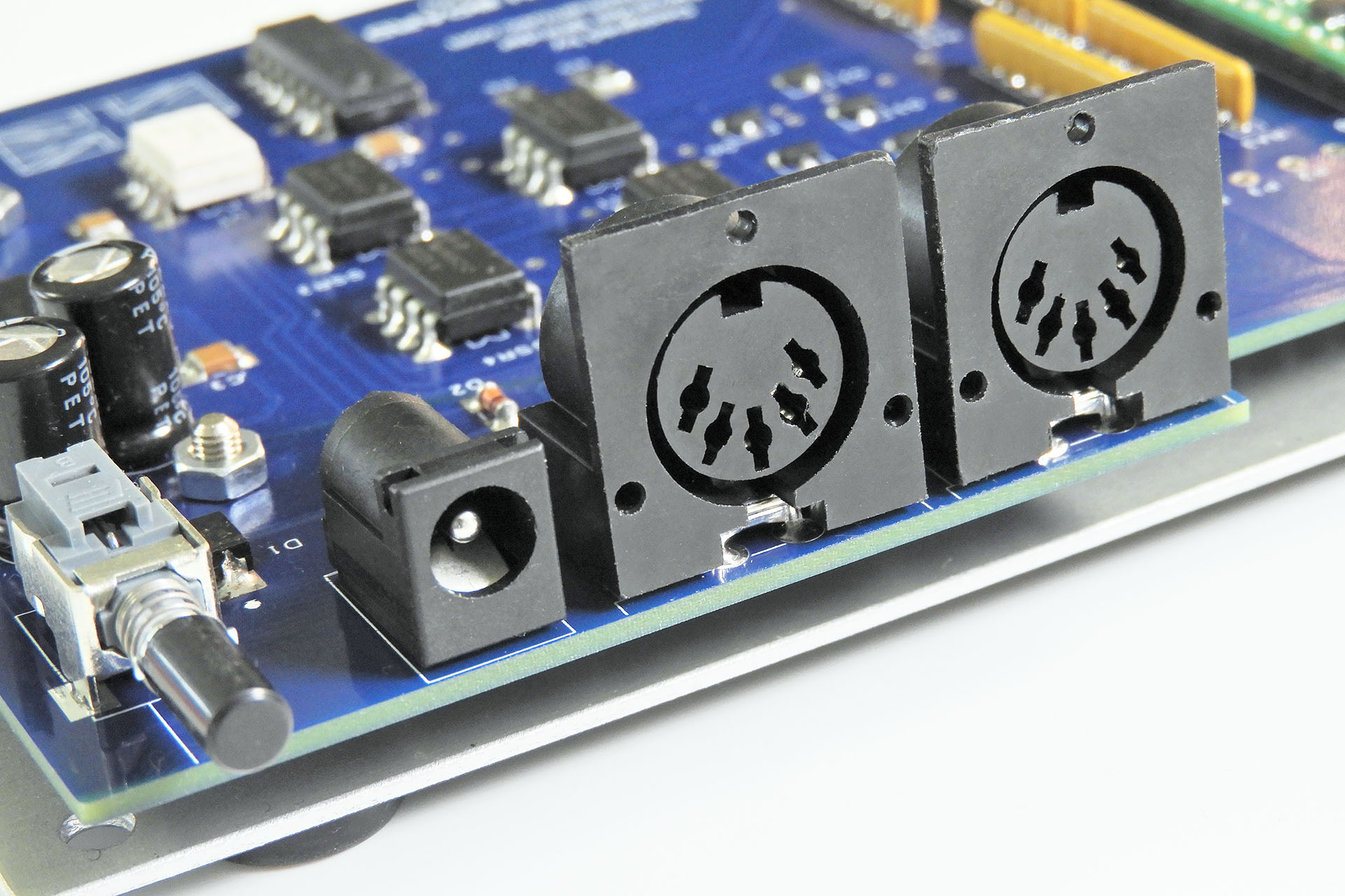
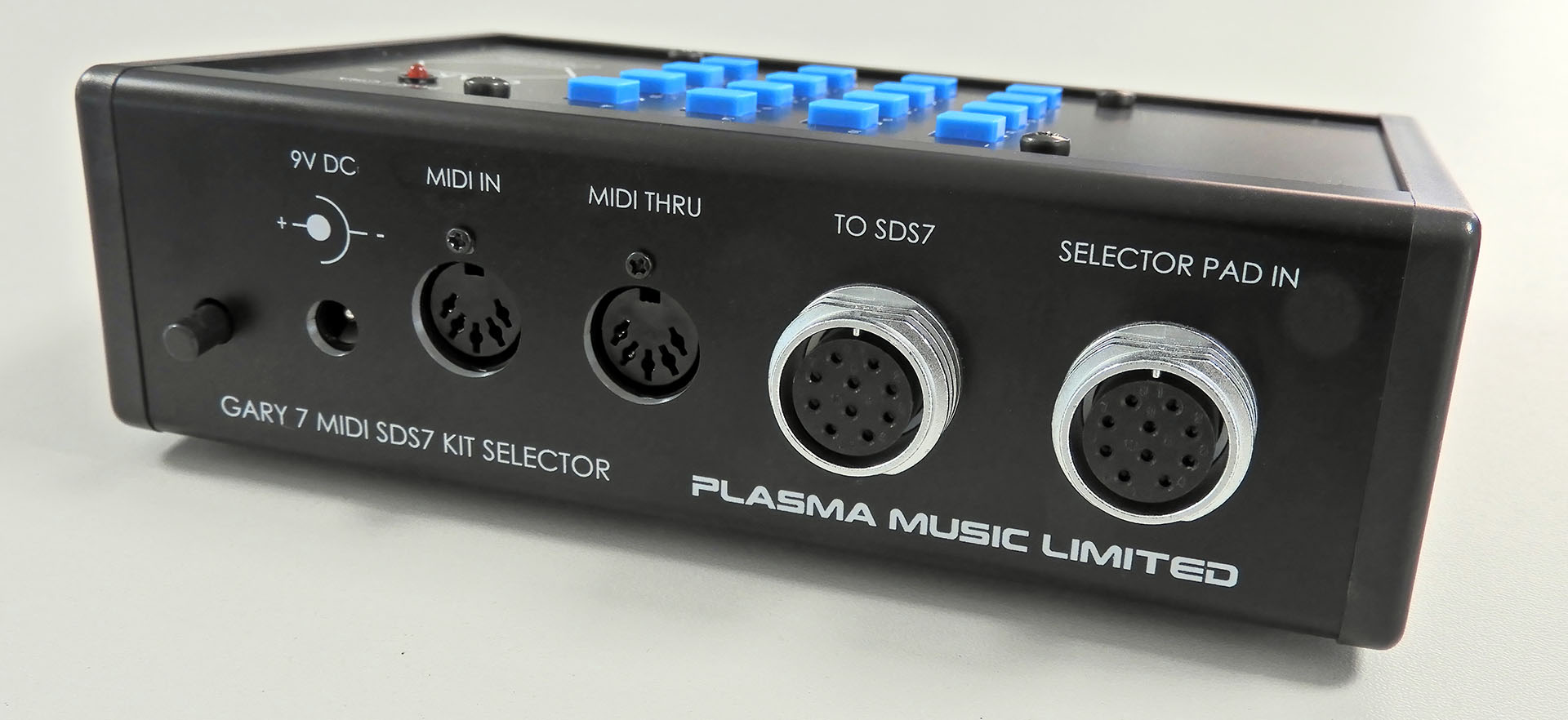
I got the switch-board right first time but the main-board had to be redesigned. I had to cut away a section of the PCB, specifically to the left of the MIDI sockets, so as to allow access to secure the chassis mounting multi-pin connectors.
Power ON / OFF, power input (+9V DC) and MIDI are all soldered to the main-board while the multi-pin connectors to the SDS7 and the selector pad (if you have one) are chassis mounted. You may notice that the DC input and MIDI sockets look slightly lifted as if they're tilted. This is to help alignment of these sockets with the sloped rear of the enclosure.
What a pain in the butt but anyway... When the second drilled case components came back from Lenton Engineering, I couldn’t wait to see how things would fit together. Indeed this time, everything lined up perfectly and WOW... this is starting to look cool.
5V MIDI
Yes, I'm quite aware that 'modern' MIDI gear runs on +3.3V so as to interface with modern processors like for example, the Raspberry Pi but... I'm a strong advocate of backward compatibility and ensuring that the MIDI gear I design will work with anything, is a big deal for me. Customers should expect my MIDI products to work, they should take it for granted!
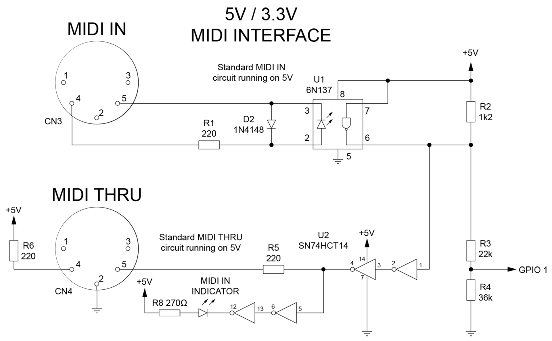
It really annoys me that many Internet gurus don't even acknowledge 5V MIDI. I'm the total opposite and to be honest, having 5V at the MIDI ports isn't a difficult thing to do anyway. As such, Gary 7 has a traditional (albeit much faster) MIDI circuit that's configured around 5v and which is fully backwardly compatible.
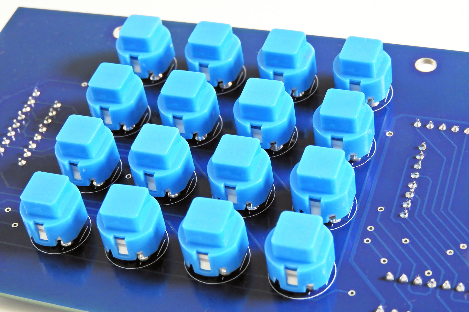
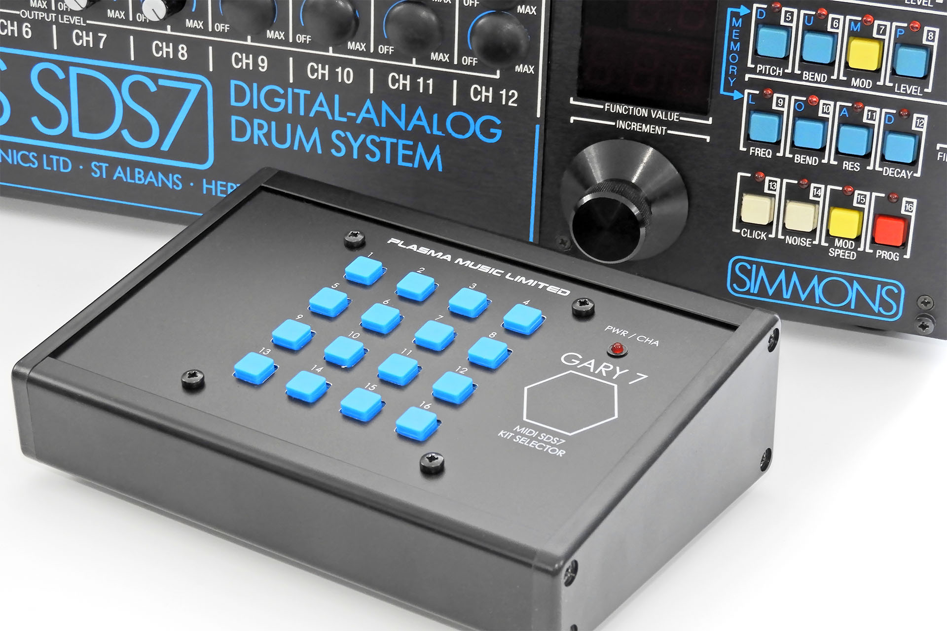
It's difficult to make a peripheral more than forty years after the original product was launched and keep a design connection with that product. I did try, though and having Simmons style switches was exactly the retro connection I was looking for.
With the PCB, multi-pin sockets and enclosure all fitting nicely, I sent a set of silk screen print files to my friend Ivor Mitchell. Ivor dropped round a couple of days later to pick up the case parts. It was only a few days later when Ivor returned with the job. I was delighted and rushed to get the electronics into the now very sexy looking case.
I had to buy another enclosure and recut the rear panel, lowering the multi-pin connector sockets by only 2mm.
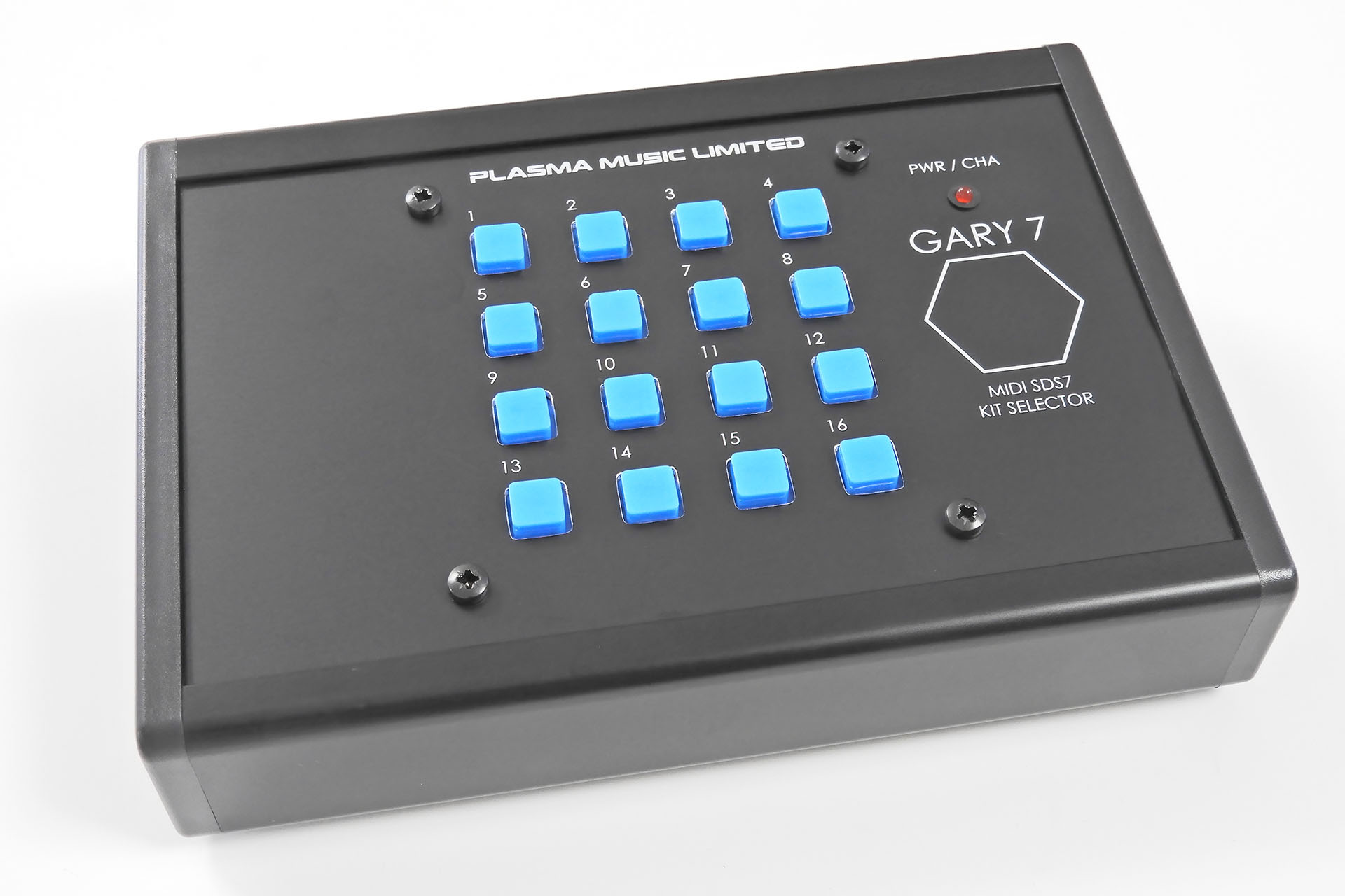
Gary 7 MIDI kit selector for the Simmons SDS7 ended up being a BIG little project. My first project involving software, my first for which I made a bespoke development board and the first time I'd used AI for anything, it was seriously fun!
Gary 7offers three ways to select kits on the SDS7:
- MIDI program change
- Manually via the sixteen on-board buttons
- An original Simmons kit selector pad
As well as being able to set the MIDI channel on Gary 7, the last MIDI program change or last button press on the front panel will be remembered and output to the connected SDS7 five seconds after the next power-up. The 'Last Command' feature will NOT remember the last pad hit on a connected Simmons kit selector pad. That's because the selector pad input and the connection to the SDS7 are simply paralleled. The pad input does not pass through the processor so any signals received from the selector pad, can't be written to memory.
THE DOWN-SIDE - GARY 7 IS EXPENSIVE! 😕
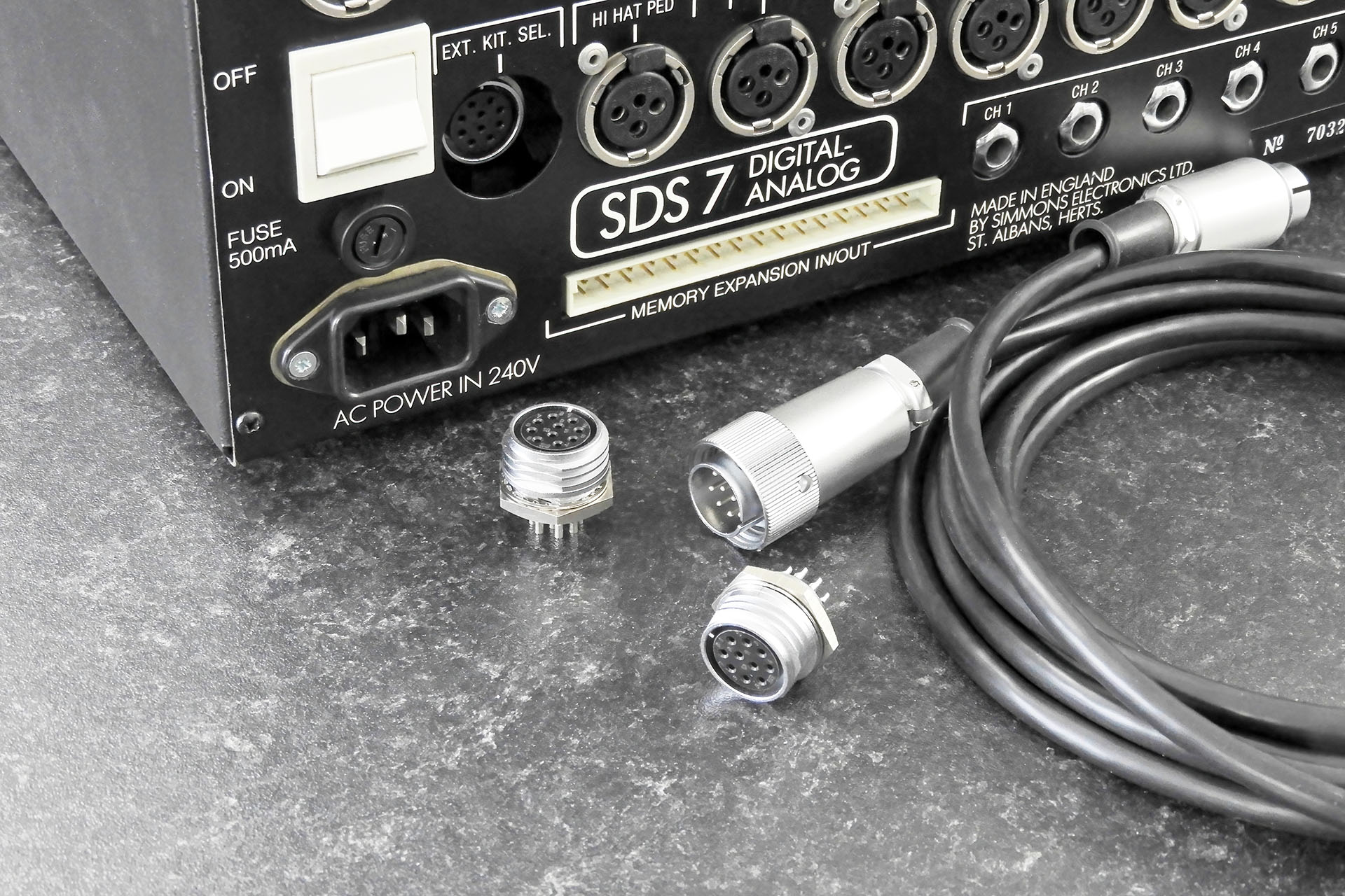
On the back of Gary 7 are a pair of female connectors, identical to the selector pad input that's on the back of the SDS7. One connects to the SDS7 and one is for connection of an original Simmons selector pad. There’s also a cable to connect Gary 7 to the SDS7. This cable has two male connectors, one at each end. At the time of writing, just those four connectors alone are over 72 GBP.
In contrast, the heart of the system, the Raspberry Pi Pico (with headers) retails in the UK for just under 5GBP!
Incidentally, in the image above that shows the connectors, take a closer look at the cable that connects Gary 7 to the SDS7. You'll notice that there's a ring around one of the connectors. This 'locking' ring is supplied by the manufacturer, with the connector. If you have a Simmons selector pad, you'll be aware that this ring is (blatantly) absent. That's because the socket on the SDS7 is recessed and unfortunately, Simmons didn't make the cut-out in the rear of the SDS7 big enough, thus making the locking ring almost impossible to comfortably access. 😕 This connector on Gary is mounted directly to the rear panel and therefore, NOT recessed. As such, I decided to include the locking ring to make things secure at the Gary 7 end of the connection. Trying to fit the connector with the locking ring to the SDS7, might be difficult!
Anyway, back to the expensive Gary 7... The Takachi CF16-11BB enclosure is pretty cool but at more than 30 GBP each, suddenly it's not so cool. Bear in mind that I have to get it drilled out and then silk-screened.
A WORD ON AI
The truth is that since this whole AI thing kicked off, I haven't exactly been keen. When I look back however, I was never a fan of having computers in the recording studio, LOL. Of course, it soon became obvious that computers in the studio was the way it was going back in the nineties and in contrast, AI is the way that everything's going now. NO! That's not quite true and there's a lot more to it than that.
I have a lot of test equipment in my lab. I have a couple of oscilloscopes, signal generators, logic analysers. I have over 2500 GBP worth of state-of the-art soldering equipment. And I've never argued that I shouldn't have any of that. All that gear helps me fix music technology and design and build some really cool stuff.
Similarly, I use two computers in my recording studio. Both computers run the most amazing software. The music that comes out of my studio however, is still mine. The computers just help me get it out.
My decision to use AI as an aid to develop the software for Gary 7 was based on the firm commitment that AI would be strictly used as just another tool. Like any other piece of equipment in my lab and like the computers in my studio, my intention from the outset was to use AI to help me develop something specific and not to get it done for me.
GIVING A LITTLE BACK
I've mentioned how Gary 7 kept me occupied and my  mind distracted while I dealt with my prostate cancer diagnosis. In the UK, one in eight men will develop the disease and while the treatment I received was quite simply amazing and the staff who looked after me were angels, I feel that more needs to be done. Wouldn't it be just perfect if I could help in some way?
I have therefore made the decision to DONATE ALL PROCEEDS from Gary 7 sales to prostate cancer research. Since I'm in the UK, the specific charity that I'm choosing to support is Prostate Cancer UK.
GARY 7 CREDITS
I repair and service a wide range of music technology from valve amps to analogue and digital synthesiser and signal processors. I also design and manufacture peripherals for a lot of this equipment. It can get a bit lonely. I don't mean that I feel 'alone', I mean that there's just no way I can know everything. Having people I can talk to is a big deal for me and as well as having the best customers in the world, I'm also very lucky to know some great techs and engineers. 😊
CONCEPT: Alexander Bhinder
INSPIRATION: Iain Melville, Mike Walden
HARDWARE DESIGN: Alexander Bhinder
PROMPTS: Alexander Bhinder
SOFTWARE: Microsoft Copilot
TESTING: Alexander Bhinder
ENCLOSURE DESIGN: Alexander Bhinder
ENCLOSURE CUTTING: Paul at Lenton Engineering
SILK SCREENING: Ivor Mitchell at S & S Quality Print
CHEERING ME ON: Ed Rose, Micha Buchner, Patrice Jacquot (my Simmons Vintage Technical Network buddies).
Gary 7 joins my other peripherals and upgrades for the Simmons SDS7 in the Simmons SDS7 Heaven category in my on-line store. Can't wait? You can buy Gary 7 here: