


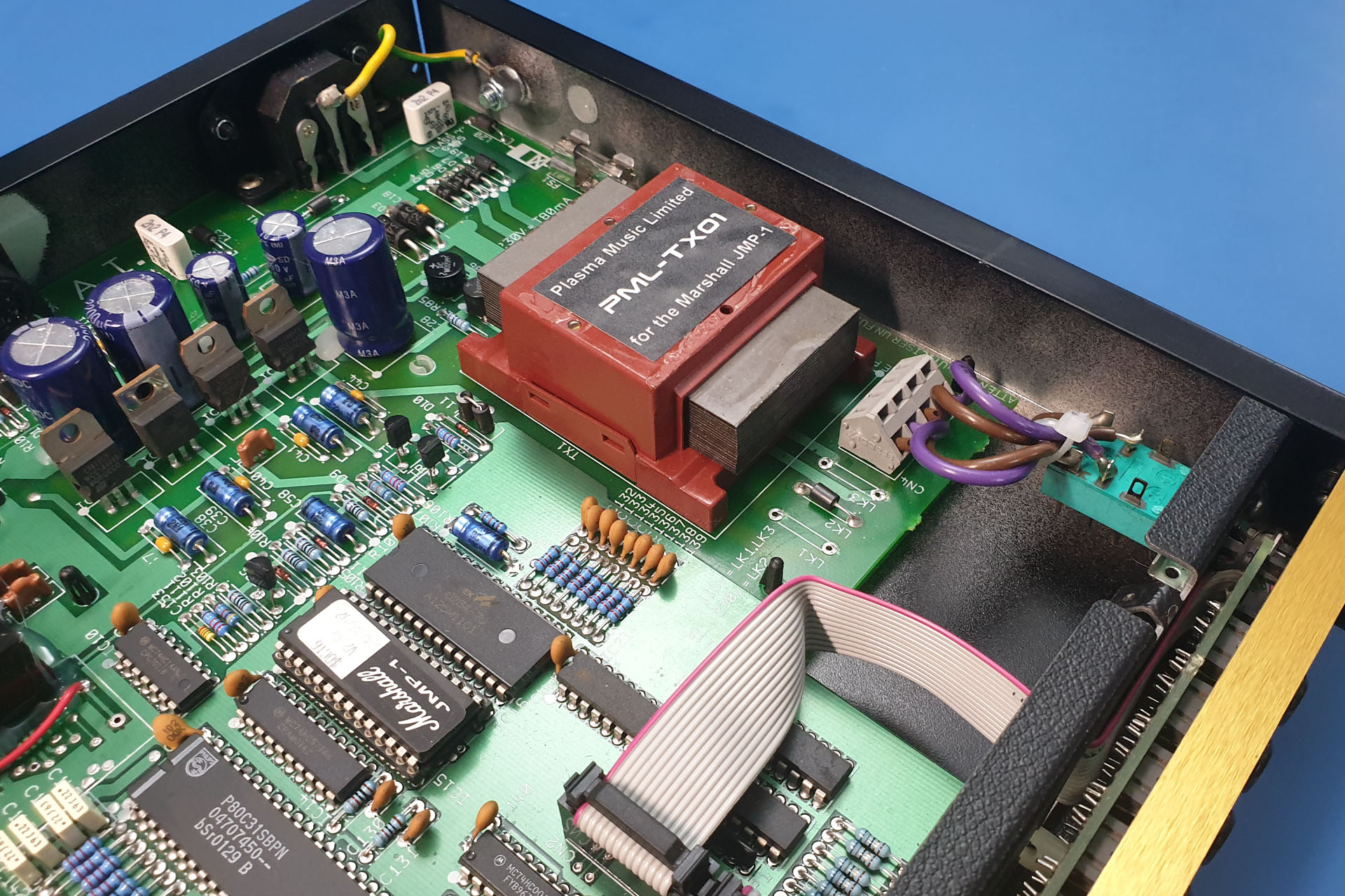
This project has taken months but after tracking down Graham Sopp, the guy who designed the original TXMA-00014 JMP-1 transformer, I'm delighted to announce that my PML-TX01 upgraded transformer for the Marshall JMP-1 is now available, featuring laminates made with a higher quality material.
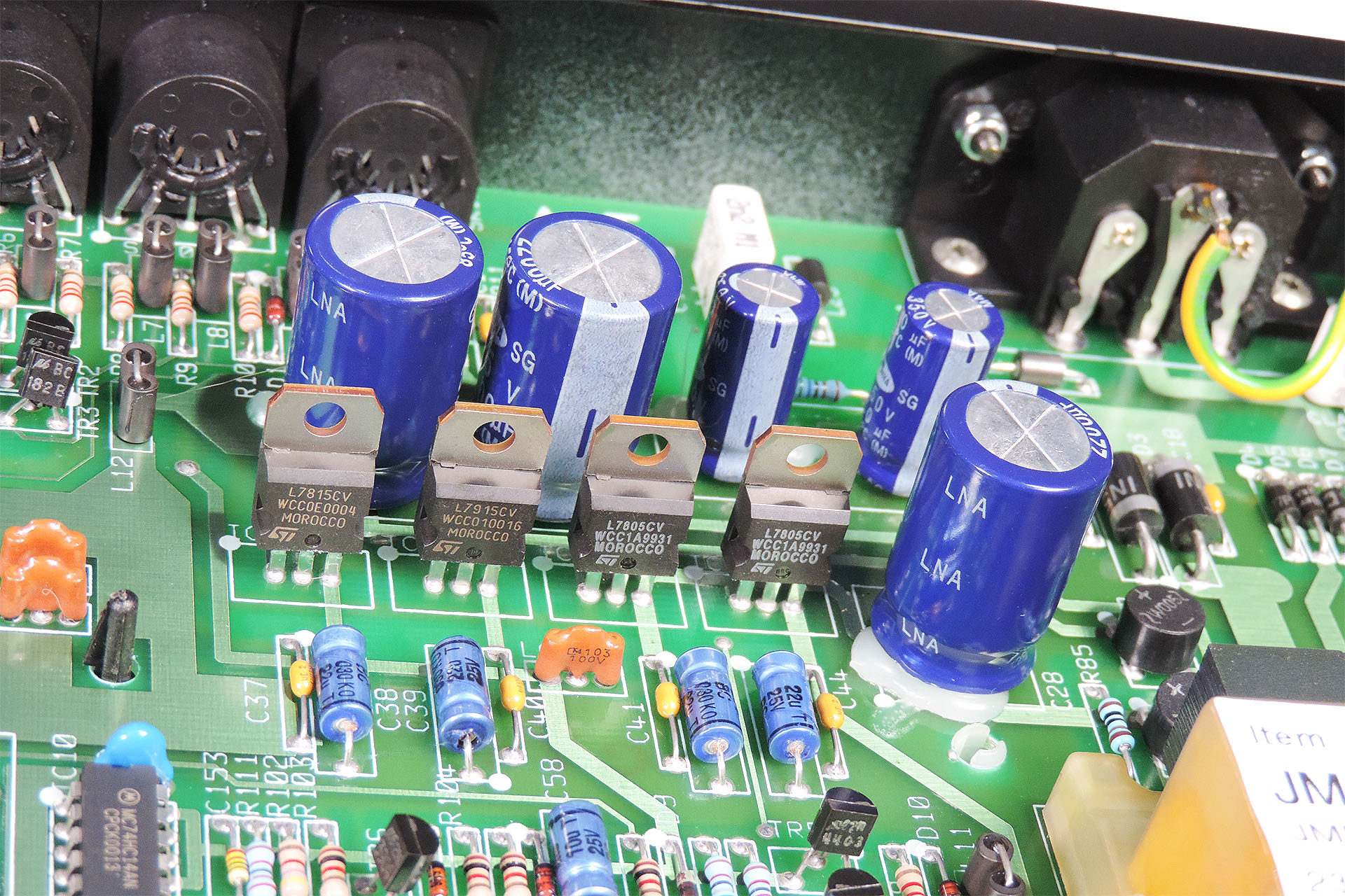
You don't need to be a rocket scientist to notice that the original transformer in the JMP-1 is not particularly stressed. Just take a peek at the regulators and you'll notice an obvious lack of heatsinks suggesting that the current draw from the supply lines is far from excessive. Measuring the input voltages to the regulators indicates that the voltage drop across them is not too much and of course we all know that the valves take very little current.
So why then, does the JMP-1 transformer get so hot?
Well, it's due to the fact that the transformer's laminates oscillate. That's right. They oscillate so much that apart from the hum, a considerable amount of heat is also produced.
WARNING - THERMAL MELTDOWN IMMINENT
I've heard of people putting rubber or foam between the top of the transformer and the inside of the JMP-1's lid, to reduce the the hum. DO NOT DO THIS!!! I've just mentioned that the oscillating laminates produce a huge amount of excess heat. Whilst the hum is annoying, with the top of the transformer in contact with the lid, any heat produced at least has a dissipation path. If you put anything on top of the transformer, it'll act like a blanket and you're just going to burn it out quicker. 🙁
Pictured below is an original TXMA-00014 that I removed from a faulty JMP-1. Displaying random behaviour and poor sound quality, when I opened her up, the results of thermal stress were quite obvious.
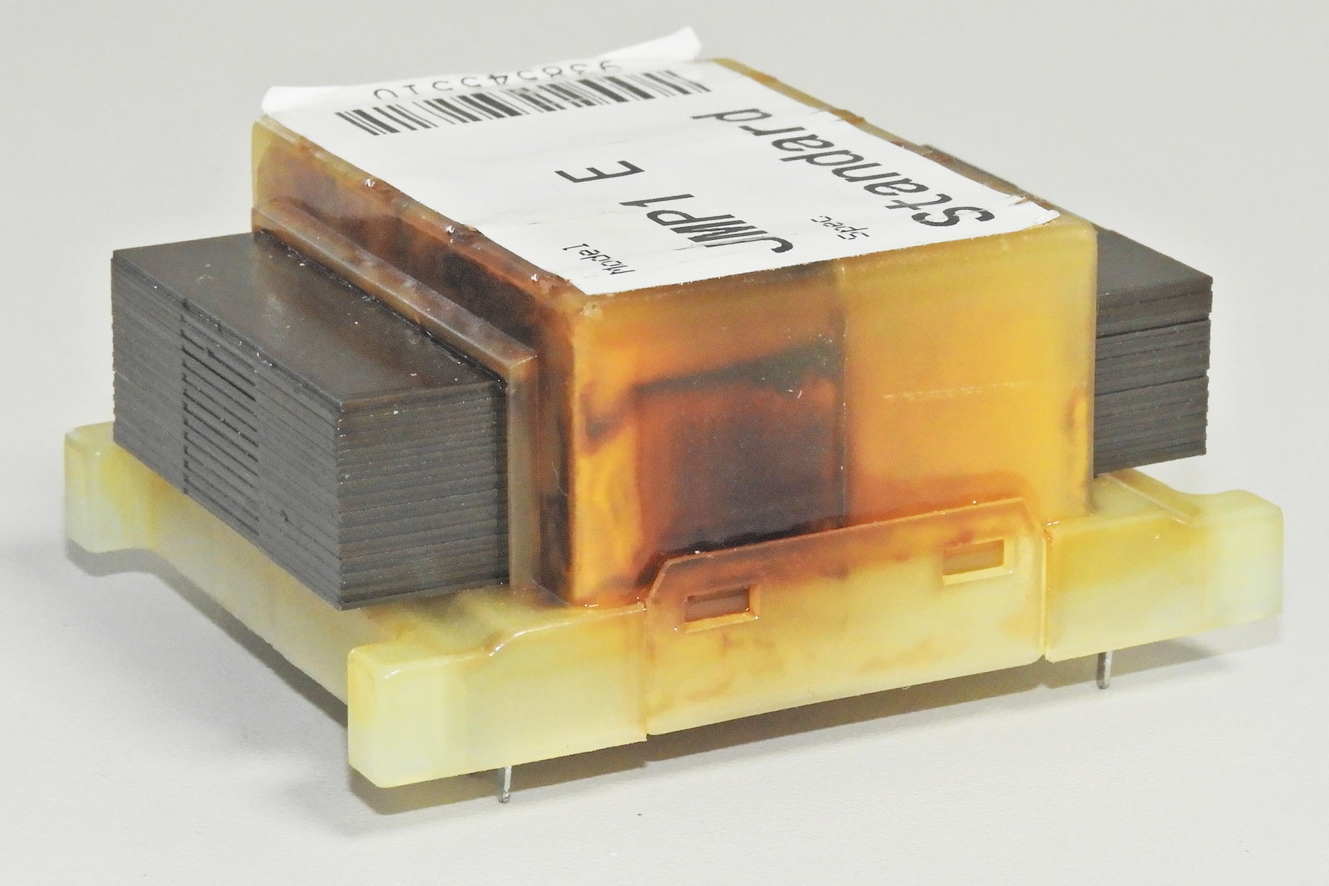
I spent a lot of time looking at the mystery of the Marshall JMP-1 humming transformer, refusing to acknowledge any issue with the laminates as I just didn't want to believe it. Once the penny dropped though, it all made sense.
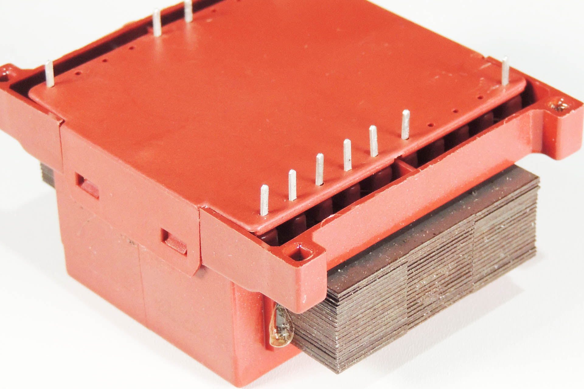
It took a while but my first batch of PML-TX01 transformers is now here. With considerably less hum and heat than the original Marshall TXMA-00014, I thoroughly recommend that you consider this upgrade.
MARSHALL JMP-1 VOLTAGE SELECTION
I regularly receive two questions from those interested in my PML-TX01:
- Is the PML-TX01 replacement transformer for the Marshall JMP-1, 240V or 120V?
- Are the voltage selector components diodes, ferrite beads or just fancy wire links?
The answer to the first question is, just like the original TXMA-00014, my PML-TX01 has two separate primary windings, each rated at 115V. So…
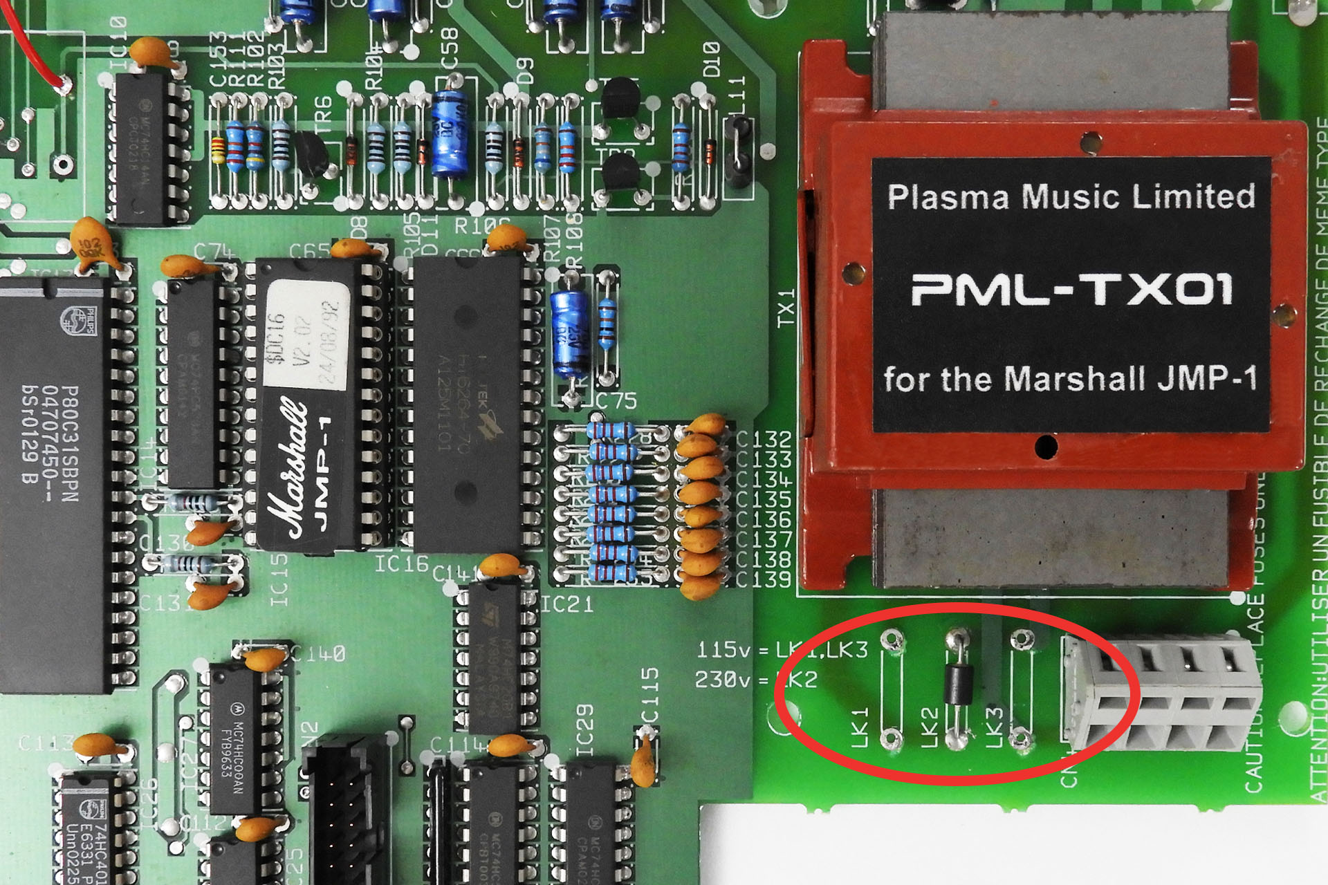
- EUOPEAN / UK VOLTAGE SELECTION. Wired in series, the primary becomes a single 230V winding which is suitable for 220V (Europe) and 240V (UK, Australia). To wire in series, connect ONLY LK2.
- USA / CANADA / JAPAN VOLTAGE SELECTION. Wired in parallel, the primary becomes a single 115V winding suitable for 120V (USA and Canada), 100V (Japan). To wire in parallel, connect LK1 and LK3.
It's quite easy to implement 240V to 120V conversion, or 120V to 240V, for example. Those eighties style wire links can make things look complicated but the original links were JUST WIRE LINKS and nothing else, so you can use wire.

It's important that the input voltage selection is chosen properly so below things are drawn that may be more representative of what you might actual see in your JMP-1.

SIDE NOTE
One might ask why the two individual primary windings are put in parallel for 115V. Why not just use one winding?
Well, a system uses a certain amount of power. Power is the product of voltage and current: P = V x I.
You can probably see now that if you half the voltage, you'll need twice the current to deliver the same amount of power. Placing the two primaries in parallel does just that, it doubles the current going into the system. 🙂
And lastly...
! ! ! DON'T FORGET TO CHECK THE FUSE RATING ! ! !
So as I've just intermated, the power requirement of a machine is the same whatever the supply voltage. Since power = current x voltage, if you're halving the voltage, you'll be doubling the current.
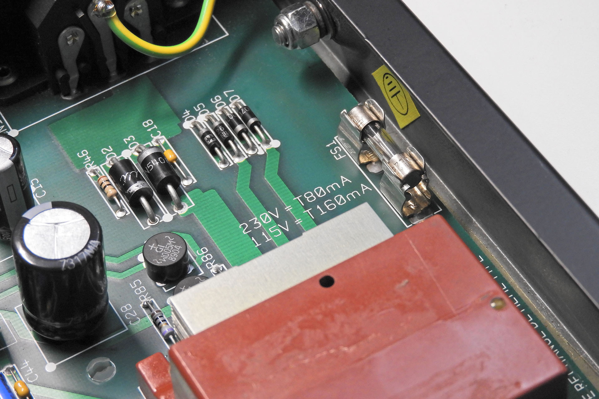
If running at 230V, the JMP-1 fuse should be 80mA (230V x 0.08A = 18.4W).
If running at 115V, the JMP-1 fuse should be 160mA (115V x 0.16A = 18.4W).
'T' stands for 'time delay' so use a time delay fuse.
A WORD OF CAUTION
The transformer is soldered to the now very old, double-sided main board in the JMP-1. Please take care when removing the original transformer. It's a relatively heavy device and the through-hole plating isn't exactly the best quality. The last thing you want to do is strip it!
IMPORTANT
My PML-TX01 upgraded transformer for the Marshall JMP-1 is a high specification drop-in replacement for the original TXMA-00014 only. It is NOT suitable for other pre-amps such as the Marshall 9001.
If you have any questions about my PML-TX01, please don't hesitate to contact me or you can just
This item regularly goes out of stock, I'm afraid but... I encourage customers to back-order. Unfortunately, the crappy e-commerce plug-in I use, only tells the links (like the one above) that the item is out of stock. What 's the bloody point of that?!?!?! So if you want this, then please just visit the PML-TX01 page on my e-store here.
UPDATE - 22nd July 2023
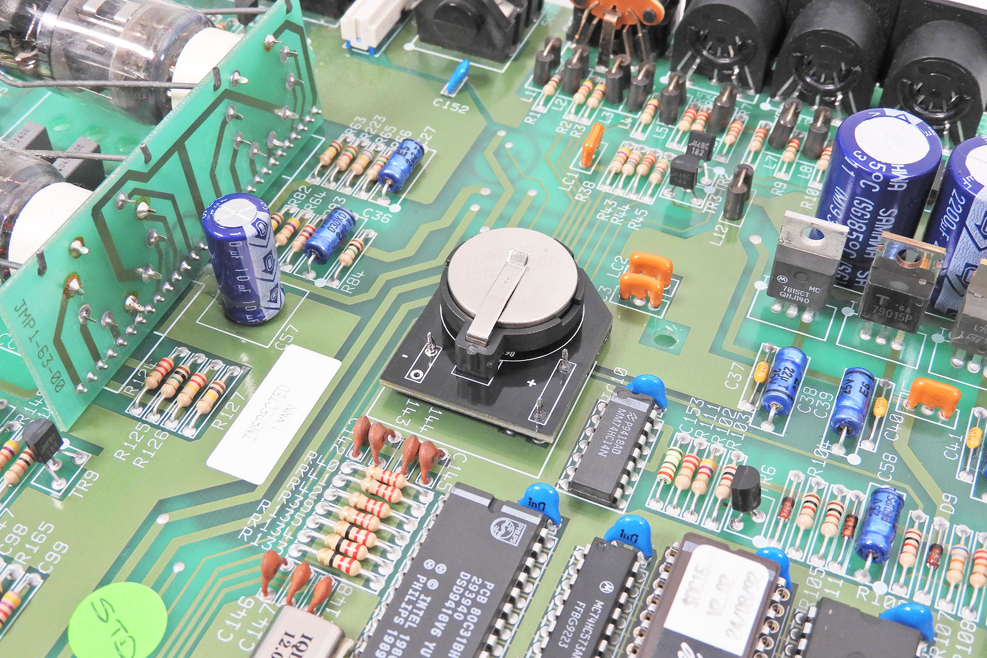
I often get asked about the memory back-up battery in the Marshall JMP-1 and with soldered batteries not really being in fashion anymore, replacements are difficult to get hold of. I therefore decided to knock up a small PCB that mounts into the original battery location but which has a CR2032 clip. This allows for easy battery changing with a standard (you guessed it) CR2032. Measuring the voltage on the battery is a little easier, too. 🙂
UPDATE - 9th February 2024

With so many bits 'n' pieces available for the JMP-1 and always thinking of new stuff to make for our favourite MIDI valve pre-map, I decided to make a category just for the Marshall JMP-1 in my on-line store. You can check it out here.
Marshall JMP-1 Service
Marshall JMP-1 Needs Attention
Eclipse Marshall JMP-1 Data Encoder Fix
Marshall JMP-1 Nuts, Knobs and Bezels
PML-TX01 replacement transformer for the Marshall JMP-1
CR2031 battery adapter for Marshall JMP-1
RE-JMP-1 replacement rack-ear reinforcement brackets
Screw Kit for the Marshall JMP-1
Oracle Battery Eliminator for the Marshall JMP-1