I do a lot of valve changes, re-capping, pot changes and re-biasing on vintage amps but I really do love a good ol' renovation. Giving an old amp a new lease of life is just so incredibly rewarding and over recent months, I've had the pleasure of working on not one but two vintage bass amp renovation projects.
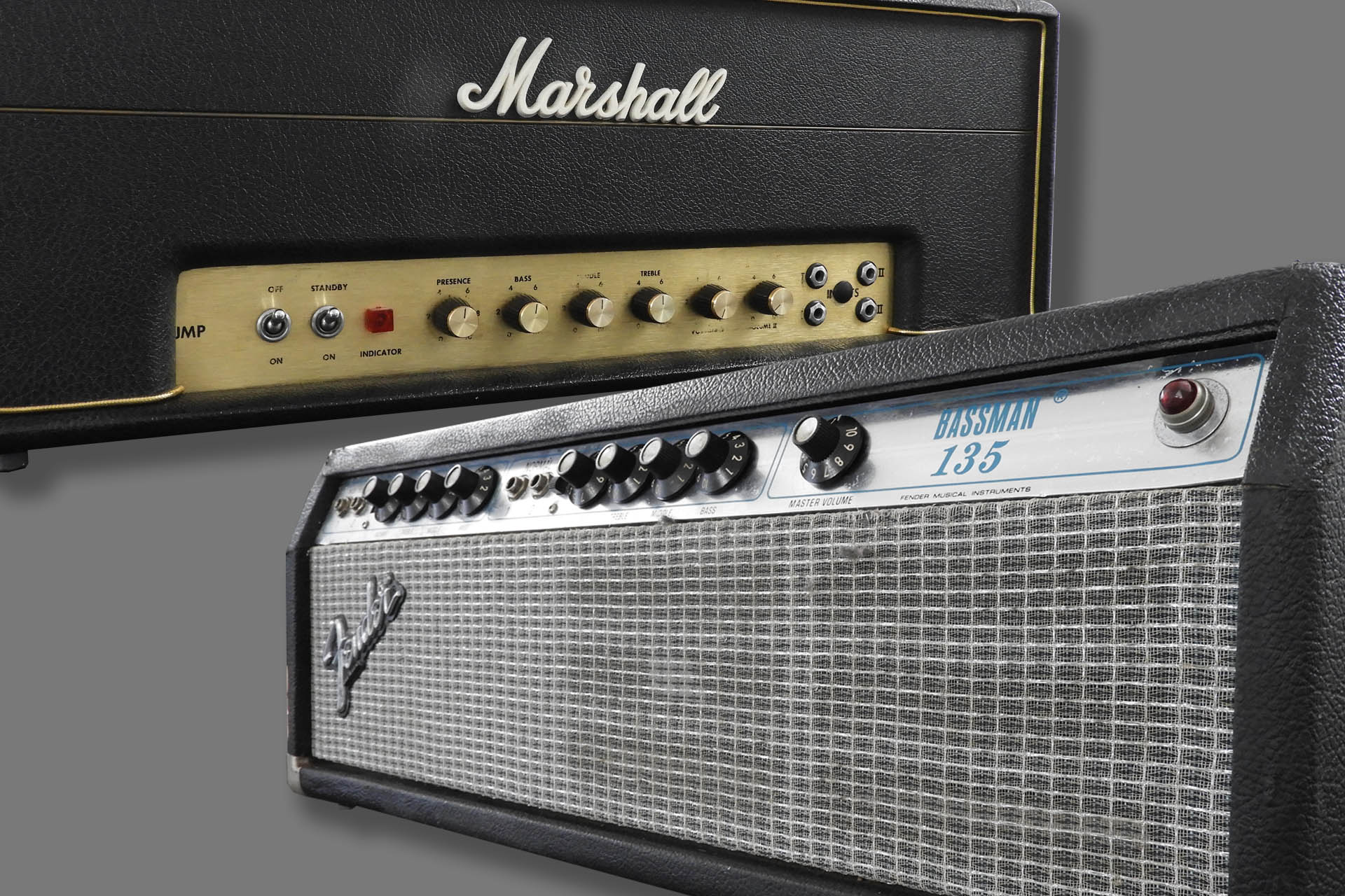
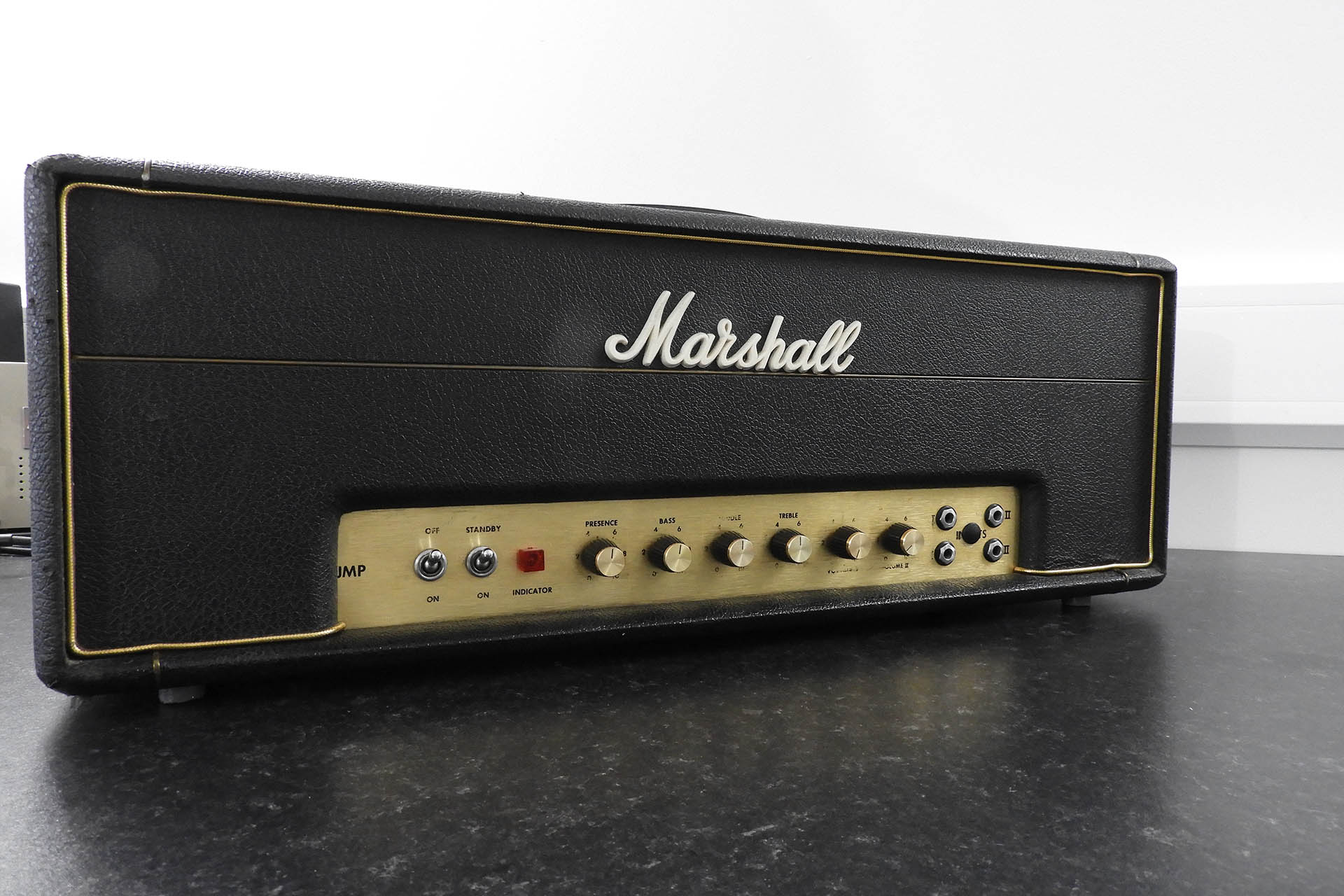
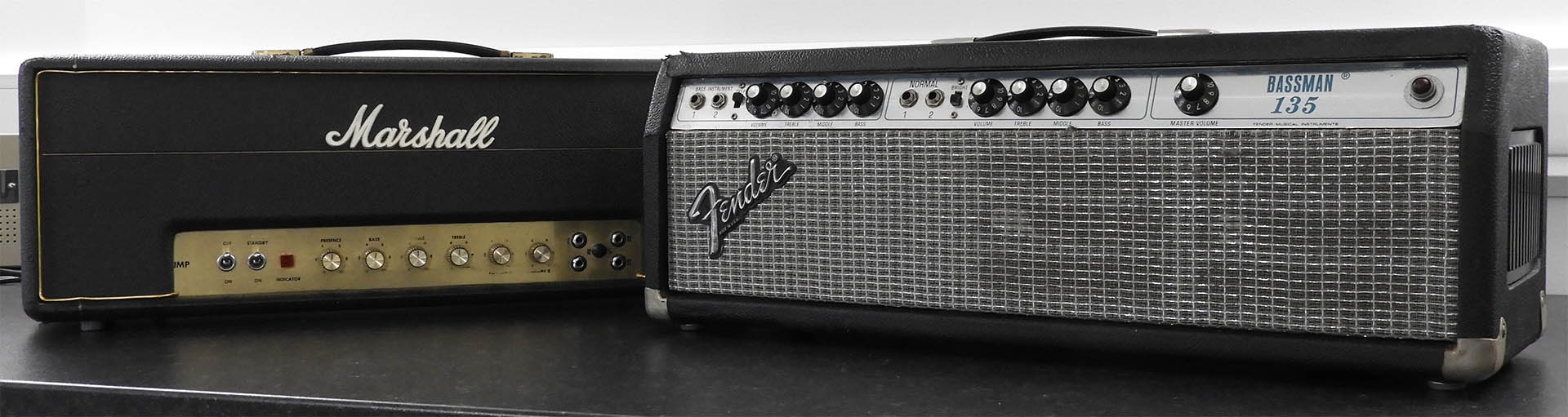
Regular readers may recall my post from April 2021 called Hiwatt Amps Found in Pyramid Hey, it was April Fools Day! 😀 Anyway, the post goes into some detail on a couple of guitar amp renovations and some weeks after the amps were returned to the customer, Adrian brought me a couple of old bass heads that were also in desperate need of attention. One was a Marshall 1986 JMP Super Bass 50W from 1969 and the other was a Fender Bassman from 1980.
Just like the Hiwatts, these amps had not just been neglected for decades but had also been modified. Such a shame when I see this but that's what people did, back in the day. Decades later, this kind of stuff now makes something like this twin vintage bass amp renovation, quite challenging. You see, you can't just rip out the obvious components that made up the mods. You have to check to see if other components were changed.
Another annoyance is that some mods involved adding potentiometers and / or sockets. All you can do is tidy up holes now left in the chassis, as best you can. It's all really quite upsetting. In the picture below, you can just make out a hole in the back of the Bassman which had an 'auxiliary' mains lead output. WTF?!?!?
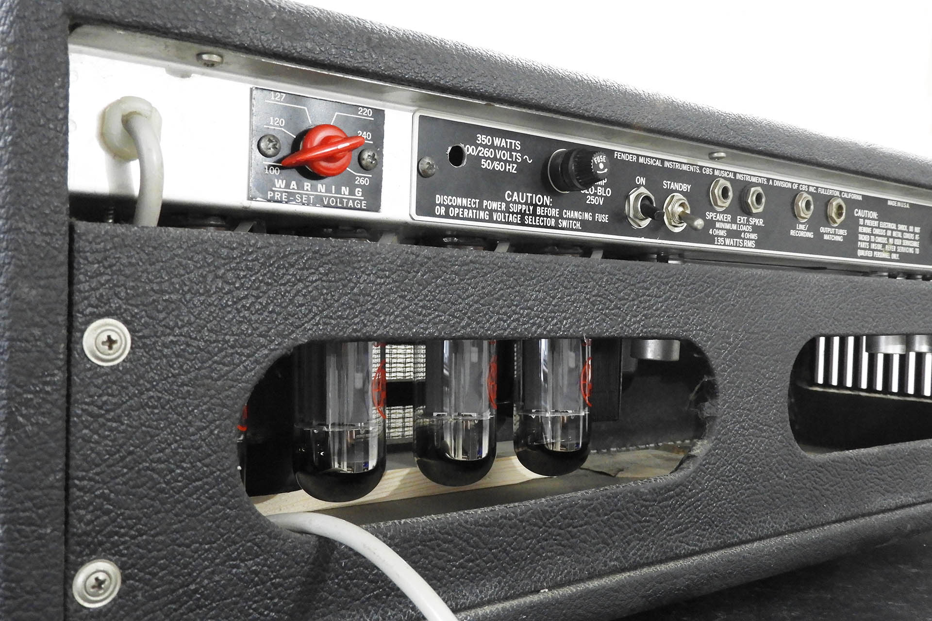
A nice new, properly biased quad of 6L6s in the back of this Fender Bassman 135 and it iiiiiis ROCKIN'.
In the middle of the four input sockets on the Marshall, there was a potentiometer. I managed to clean up the hole and insert a plastic cap.
Anyway, it took me months to sort out these babies and I have to say that they now look, sound and even smell very different to when they first came in.
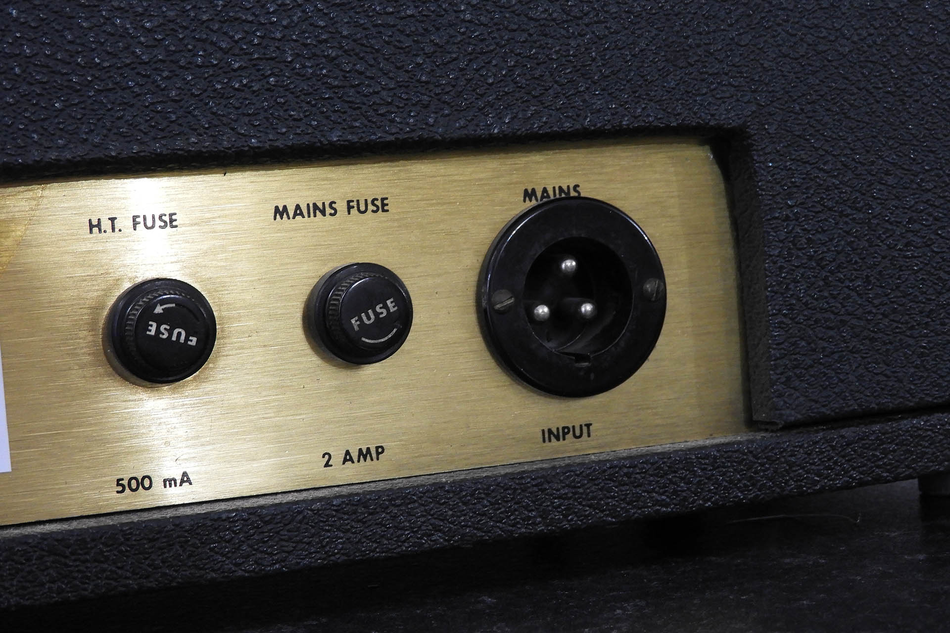
Taking stuff back to the Marshall factory is an obvious option but the Marshall service team is obliged to swap out the 3-pin Bulgin power inlet socket for an IEC C14. This involves mashing out the original circular cut-out to a rectangular receptacle that'll take the modern connector. While safe, it looks awful.
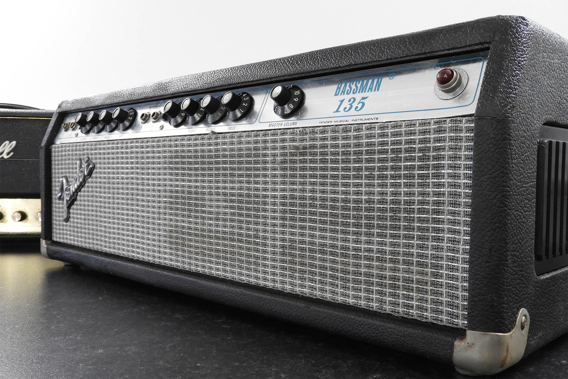
Back in the day, many guitarists used bass amps for their (obvious) depth. In fact, back in the eighties, my friend Leon Lawson who used to tech for Michael Schenker, put me on to this. Being a Marshall man myself however, I'd forgotten just how incredible some of the Fender bass amps sounded with guitar! This Bassman 135, now loaded with a properly biased quartet of 6L6s, had thee most beautiful, smooth overdrive ever. Really chunky and full bodied, the bottom end was well balanced and not at all muddy, while the high-mids and top end maintained fantastic definition, with just the right amount of sparkle. Don't forget, this amp has a normal (non-bass instrument) channel, too.
Glad I don't gig with this stuff anymore. The Fender Bassman 135 is seriously heavy but what an amp!
After putting the oh-so-heavy chassis back into the cabinet and final testing, I just couldn't stop playing this beast. The eq didn't sound as dramatic as that on the Marshall but you know what, I just left everything on 5 and played my heart out! Wow! What an amp.
PLEASE TAKE CARE IF YOU'RE CONSIDERING BUYING A VINTAGE AMP
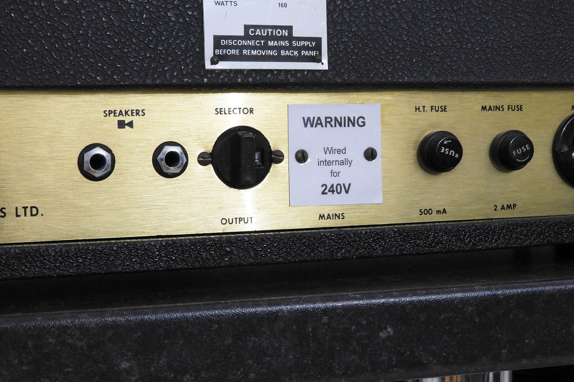
I've already mentioned the power input socket on the Marshall but the voltage selector on this generation of amp is really dodgy. In fact, the one on the Marshall was too loose to leave as it was. I contacted the customer and advised him that I should wire the amp internally for 240V operation and put a plaque over the voltage selector at the back of the amp. He agreed. If I come across a nice, tight selector, I'll contact Adrian and tell him that I can change it.
An indication of the safety mod I implemented but which can easily be put back to original, once I get a good replacement mains selector switch. Not ideal but the speaker impedance selector is good.
The speaker impedance selector is the same switch but of course, with different markings. For the health of the amp, it's equally paramount to ensure that this component also has a tight fit between the male and the female. If the male part of the selector accidentally falls off, the amp will go 'open circuit', a condition that'll blow the output transformer. They're expensive to buy and very time consuming to replace. On top of that, a modern replacement won't sound like an aged device.
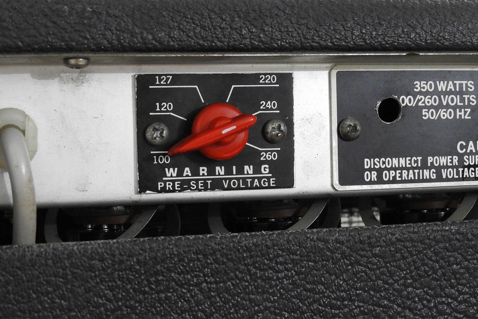
The Fender isn't much better, to be honest. While at least an enclosed switch which doesn't have two parts, the voltage selector on the back of the Bassman 135 is really quite loose and can easily be nudged by accident.
Almost as bad as the Marshall, the voltage selector switch can easily be nudged by accident and just where it's pointing, isn't always clear.
BOTTOM LINE: If you're thinking of buying a vintage amp, you simply MUST check the input voltage and speaker impedance selectors.
Vintage valve amp renovations often take weeks and sometimes longer. They're very involved but I love the challenges and the feeling when you get to the end is quite rewarding. At 60 GBP plus VAT per hour, there's no way I can charge for the actual time I spend on stuff like this. Inevitably I try to quote something which I feel balances out the time spent, the value of the item and provides a reasonable finite figure for the customer. It can be a hard call but to put things into perspective, I quoted Adrian about 2500 GBP including labour and parts for both amps. Within a couple of e-mails, we agreed on 2150 GBP. That's more than a 10% discount and is even further from the cost of the time I spent on these things. On the other hand, I'm happy that Adrian's happy and I'm even more happy that these amps may have another fifty or sixty years in front of them! 🙂
These amps are in quite a different condition to when they came in.
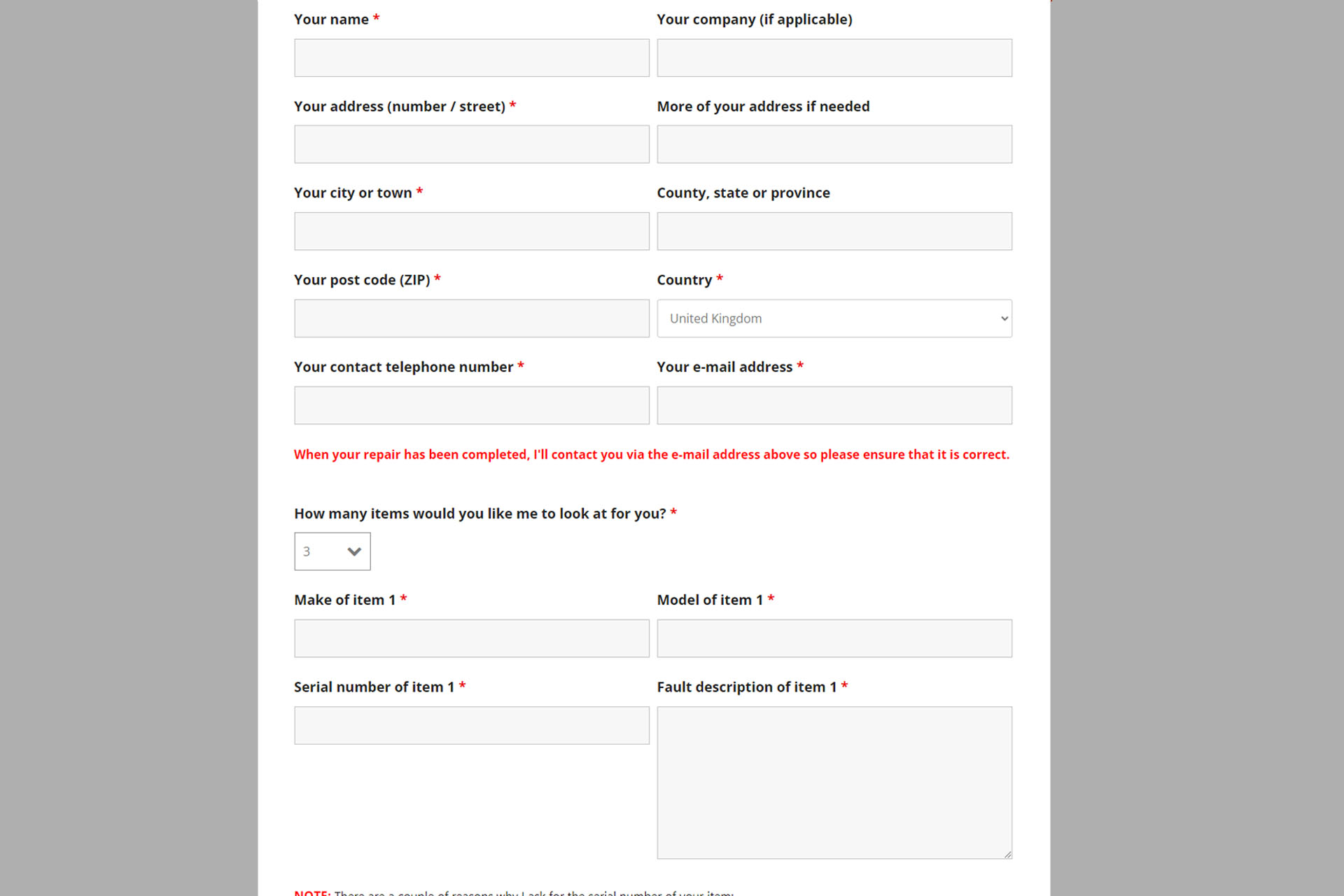
Over the past year, more and more customers are wanting to bring me several items at the same time which is great but I’ve felt embarrassed asking them to complete a copy of my Service & Repair Form for each item.
Well, last night, I redesigned my form and customers can now book in up to four repairs simultaneously. Details for each item need to be completed but customer contact details only need to be done once.
There’s a fine balance to be struck between keeping things simple and straight-forward but gathering relevant information at the same time. When things get busy, it’s important that I can easily keep track of what’s going on with all the customer units I have.
So, if you need to bring me a few items for repair, service or upgrade, please check out my NEW Service and Repair Form! 🙂
Today I received an e-mail with a rather interesting question; a MKS-70 owner, uses upper and lower voices as two separate instruments and suffers from crosstalk. He asked me if would Nebula reduce crosstalk. Such a good question.
Cross talk can be considered as a type of interference. Unlike noise high up in the electromagnetic spectrum such radio frequencies (RF) however, crosstalk specifically pertains to audio.
Fundamentally, crosstalk is a 'leakage' of signal between two (or more) audio channels and occurs when a signal flowing in one audio circuit is induced into the signal flowing in another audio circuit. This can occur for one of several reasons such as:
Signal sources are high impedance.
Signal destinations are low impedance.
Earth isn't absolute and actually carries a small voltage offset or even some audio.
Normally associated with the channels that make up a stereo configuration (left and right), in the MKS-70, we should also consider potential crosstalk between the outputs of each module-board (as per the question at the beginning of this post).
So let's have a look at some aspects of the MKS-70 which might produce crosstalk...
Firstly, the audio outputs of each module-board come straight out of a pair of M5218L op-amps and as we all know, op-amps have a very low output-impedance. Hence, the module-board outputs shouldn't contribute significantly to crosstalk. We can therefore cross reason 1 off our list.
Interestingly, there are no low-value resistors on the outputs of those M5218Ls, which you might normally expect. That's because Roland used series resistors later on in the chain (on the jack-board), to provide passive mixing for the headphone amp.
Coming off each MKS-70 module-board, there are four wires; left audio / left earth and right audio / right earth. There’s nothing connecting the two module-board audio paths at this point.
The two sets of connections (eight wires all together) go straight to the jack-board. Here, Roland implemented an ingenious passive switching / mixing system which automatically directs appropriate signals depending on which jack sockets are accessed.
On the original jack-board, the four audio signals are also combined passively, to provide a stereo headphone output and a mono output.
This passive mixing network would potentially present the outputs from the module-boards with a relatively low input impedance but... there's more to it than that; the headphone op-amp is in non-inverting mode and so each input is strapped to ground via a resistor. The resistor has a value of 100kΩ so in parallel with the very high input-impedance of the 5218P (about 5MΩ) the input-impedance of each channel is roughly the same; 100kΩ, which is pretty good. The value of this resistor is critical and requires a bit of a balancing act by the designer. Yes, you want it to be high but if it's too high, then noise will be introduced into the system and we definitely don't want that.
So with a high input-impedance, we can also cross reason 2 off our list.:)
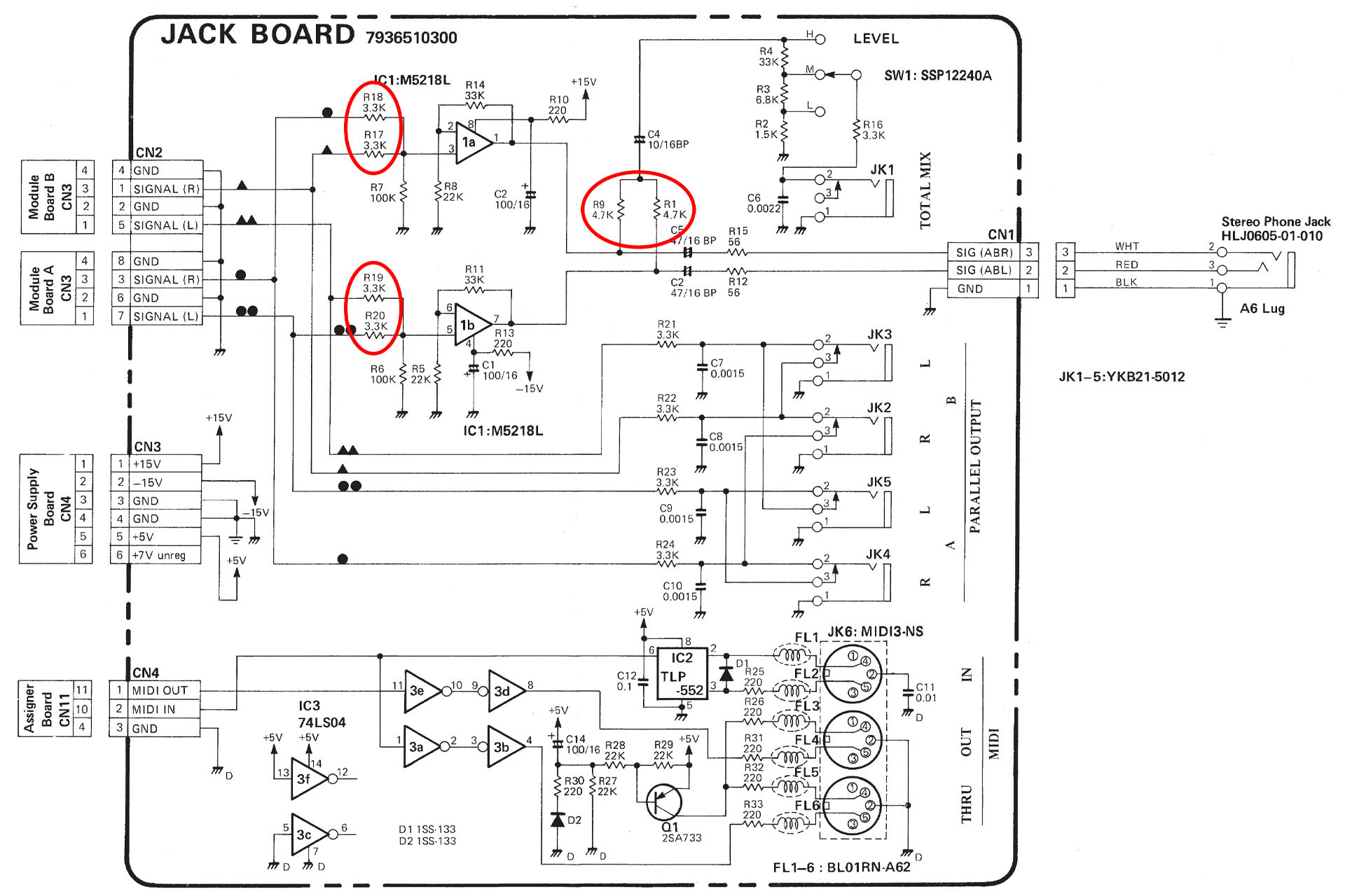
MKS-70 jack-board schematic highlighting in red, passive mixing of voice-board outputs to stereo for headphone output and mono for mono output.
SO WHY ARE THERE TWO EARTH WIRES COMING OFF THE NODULE-BOARD TO THE JACK-BOARD?
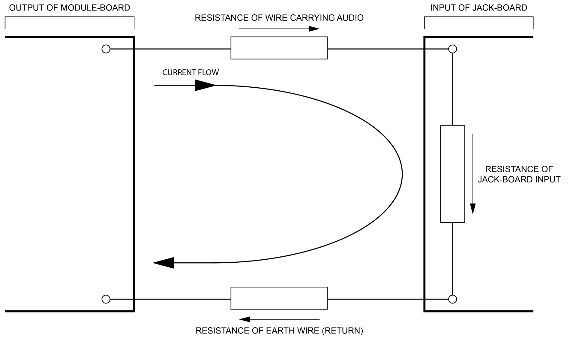
Consider a single audio connection between a module-board and the jack-board, as a kind of potential divider. The signal carrying conductor is one resistor, the input impedance of the jack-board is another resistor and the return path (earth) is a third resistor. Did you notice what I just did? We're treating the earth here as a conductor. Okay, so the voltage drop across each wire will be directly proportional to the input impedance of the jack-board, right? Hence, if the input-impedance of the jack-board is low, then the voltage drop across the wire carrying audio and the earth wire (return) will be proportionally higher than if the input-impedance of the jack-board was high.
Image shows a potential divider network between the output of a module-board and the input to the jack-board.
Now then, if the earth (return) path is shared between left and right outputs for example, crosstalk between those channels could (might) occur. Having separate earth connections (return paths) for each audio path, reduces the potential for that. That's why each audio channel in the Super-JX, has its own earth connection between the module-board and the jack-board.
In my humble opinion however, the potential for crosstalk as a result of using one earth connection between the module-board output and the jack-board input in the MKS-70, is minimal. The physical distance between the two points is only 25cm or so. The output-impedance of the module-board is low and the input-impedance of the original jack-board and indeed Nebula, is high.
With identical sound engines, digital control and similar operational functionality, the very obvious difference of internal layout, makes the JX-10 a very different animal. The physical distance between the module-board outputs and the jack-board inputs in the JX-10, is quite different than in the MKS-70. Running substantial distances, the cables that carry audio in the JX-10 are also strapped together with data and power carrying wires, giving the JX-10 much higher noise and crosstalk levels than its rack-mounted cousin. It's of no surprise then, that the audio cables in the JX-10 are, err... screened! Indeed audio destined for the outputs, has a tough time in the JX-10.
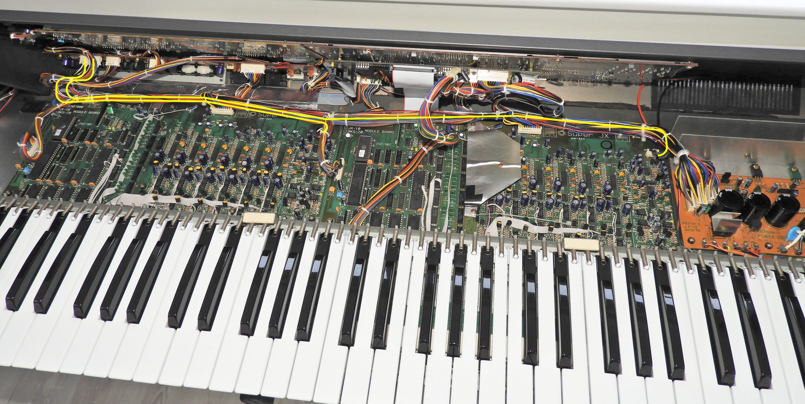
Highlighted in yellow, you can clearly see that the audio cables from the module-boards to the jack-board in the JX-10, are in the same long loom that carries power and digital signals. In contrast, the same cables in the MKS-70 are much shorter.
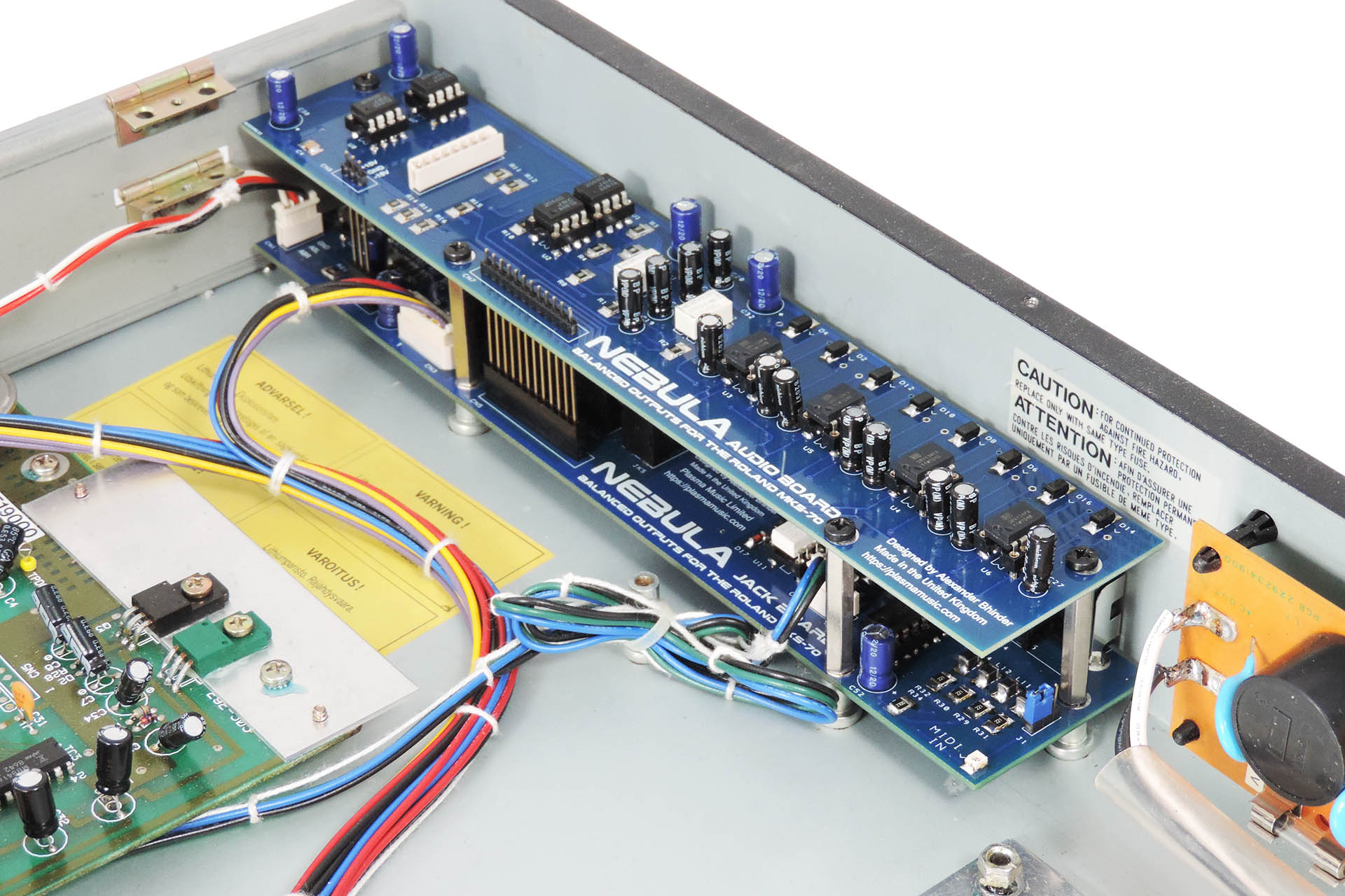
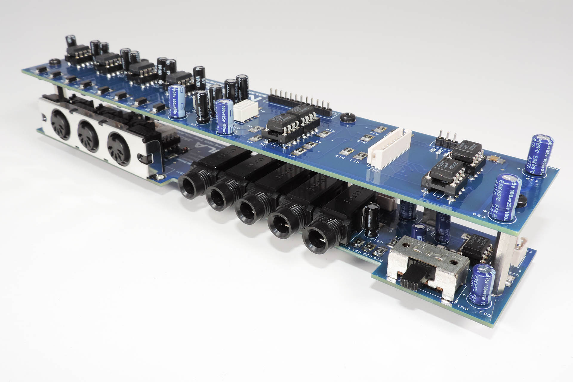
For balanced operation, the jack sockets on Nebula are of course, 3-pole and not 2-pole as per the original jack-board. I wasn't able to find 3-pole sockets with switching, that fitted next to each other and hence, lined up with the holes in the rear of the MKS-70. Neither could I therefore, emulate Roland’s rather ingenious automatic output selection system. Using active components and taking advantage of the original level-selector switch cut-out in the rear of the MKS-70 chassis, the outputs of Nebula are switched manually from stereo to individual operation.
On a side note, manual selection of Nebula's output configuration has another slight benefit; all four outputs from Nebula can permanently be left connected to a mixing desk. With the original jack-board, if you did that, your MKS-70 would only be able to output four independent channels and would be unable to go stereo.
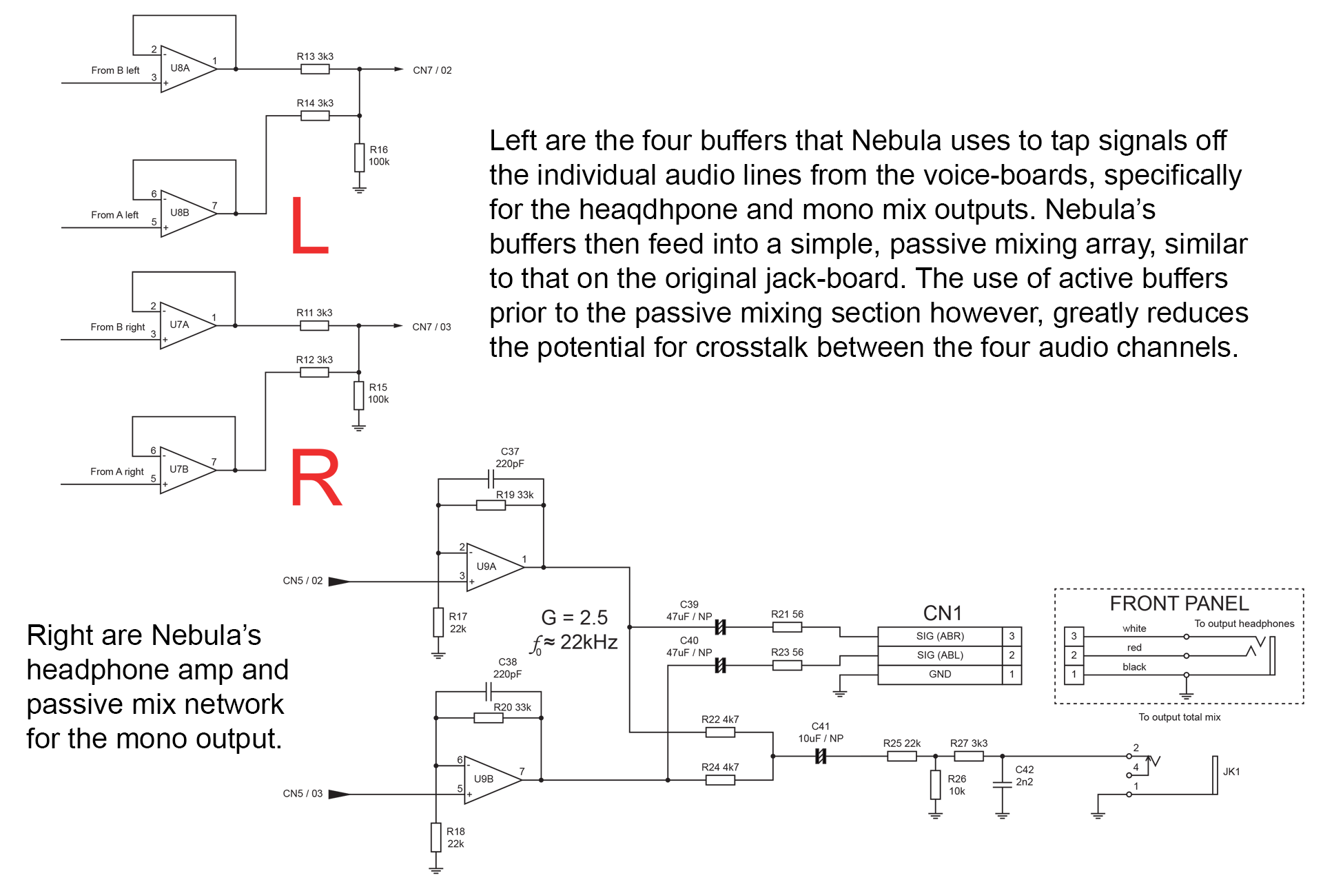
Instead of tapping and mixing the signals for the headphone output mix from the individual signals from each module-board via resistors (R17 - R20 in the diagram above), Nebula uses op-amps. It would have been quite tempting to design Nebula with very high input-impedance but I didn't want to introduce more noise and keeping things in perspective, the original 100kΩ was / is just fine.
I should mention that similar to the original Roland jack-board, Nebula's mono mix signal, is derived via passive mixing of left and right signals but only after Nebula's headphone amp. The headphone mix is tapped off the individual signals via active buffers. The inputs of these buffers are in parallel with Nebula's channel input buffers so the input-impedance of each channel remains at about 100kΩ. This arrangement significantly reduces the potential crosstalk.
Similar to the original jack-board, Nebula uses passive mixing to derive stereo and mono mixes specifically for the headphone and mono outputs. The mixing network however, is fully buffered from the channels that are sent to the four main outputs.
Before we consider earth integrity as a potential source of crosstalk, let's take a quick look at the potential for inter-board crosstalk (which after all, was the question at the beginning of this post).
The output-impedance of each module-board is of course, identical so again, we're not going to consider that to be an issue.
The earths (audio signal return paths) on each board are completely separate to each other so that's not going to be an issue, either, although if shared, I'm not convinced it'll make any difference.
The input-impedance of each channel on the original jack-board and Nebula is about 100kΩ so that's fine and not really an issue.
Another design feature of Nebula which reduces inter-board crosstalk considerably, is that left and right channels are processed through the same dual op-amp. The left and right outputs from one module-board are processed though one dual op-amp.
It's interesting to note that the audio connections from the module-boards on the MKS-70 terminate at the jack-board end, with a single 8-way Molex connector. Each module-board audio connection on the JX-10 however, has its own 4-way Molex connector on the JX-10 jack-board. It seems that Roland engineers were aware of potential issues on the JX-10 and went to some trouble in an attempt to address them.
So finally, we need to look at the earth on our Super-JXs.
As we know, many Roland instruments were made available with IEC 2-pin C9 power input sockets which means that they weren't directly connected to mains earth. Hmm.... So perhaps the reason we have crosstalk problems in the first place, is because some Super-JXs don't have a good earth.
Taking a few steps back and thinking about the JX-10 again, solid earth or not, the JX-10 is just not as heavily screened as the 100% steel enclosure of the MKS-70. That means that although Roland tried its best, by the nature of the beast, external EMF could mess things up for the keyboard version of the Super-JX.
Incidentally, if you're concerned about the earth status of your Super-JX, then don't be. You could always buy my IEC C14 earth bonding kit! 🙂
Each of Nebula's four main outputs, are driven by separate balanced line drivers. These devices are single-channel and other than power and earth, there's no other (common) connections between them. Hence, there won’t be any crosstalk introduced at that stage.
On the near right of the top (audio) board of Nebula are the four dual op-amps and on the far left are the four (independent) balanced line drivers.
One final, perhaps slightly controversial point to consider, is "how stereo is the stereo output from a Super-JX module-board?" That's another really good question. It's only the chorus effect that makes the left and right audio channels, different. WOW!!!!
So to answer the original question; "would Nebula reduce crosstalk when using upper and lower voices on the MKS-70 as two separate instruments?" YES, most definitely.
Nebula doesn't introduce any potential for crosstalk but with no passive channel switching / mixing, it definitely has better crosstalk performance than the original jack-board.
Service notes for the Roland MKS-70 can be obtained here: https://www.synthxl.com/mks-70/ (PLEASE don't forget to leave a donation).
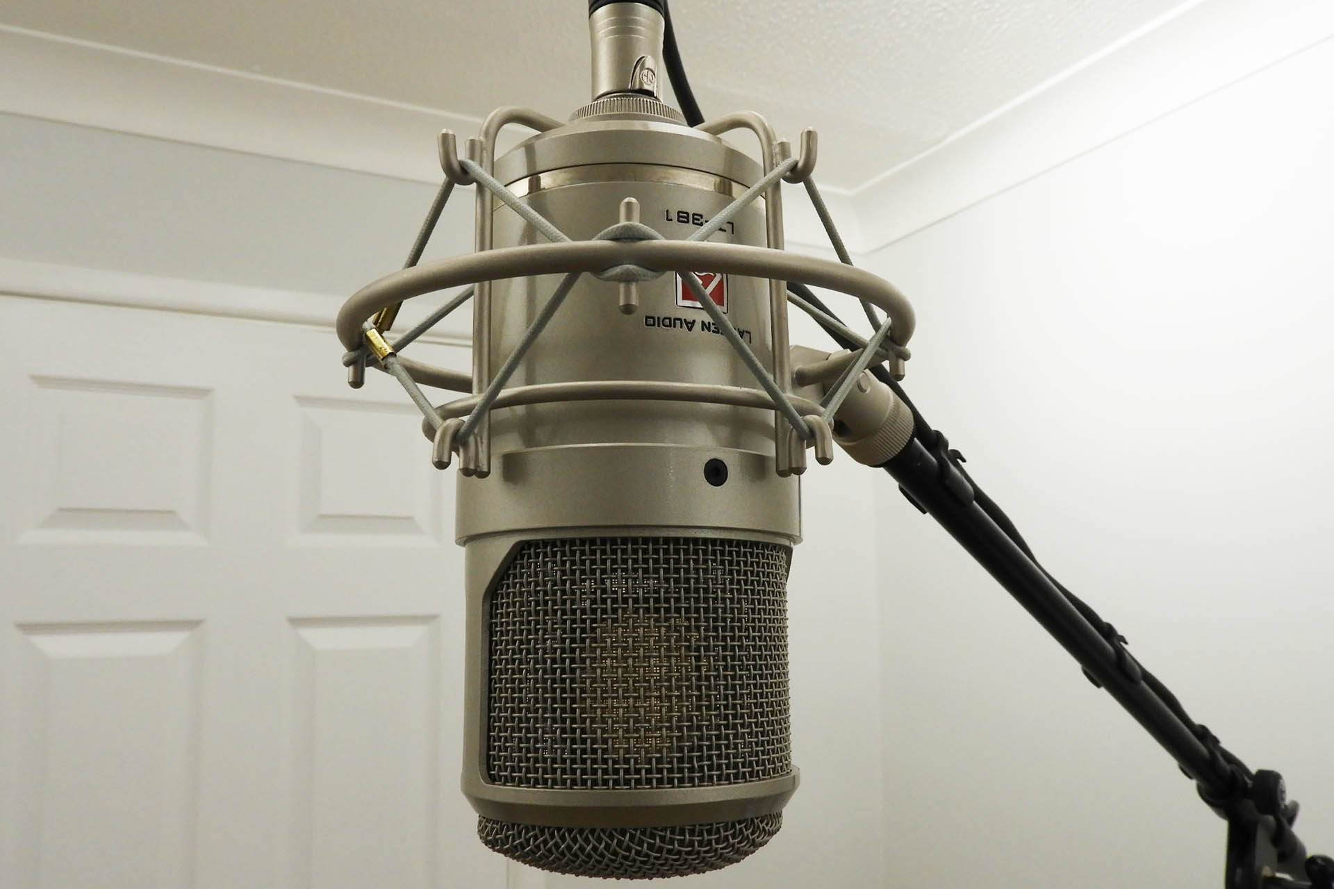
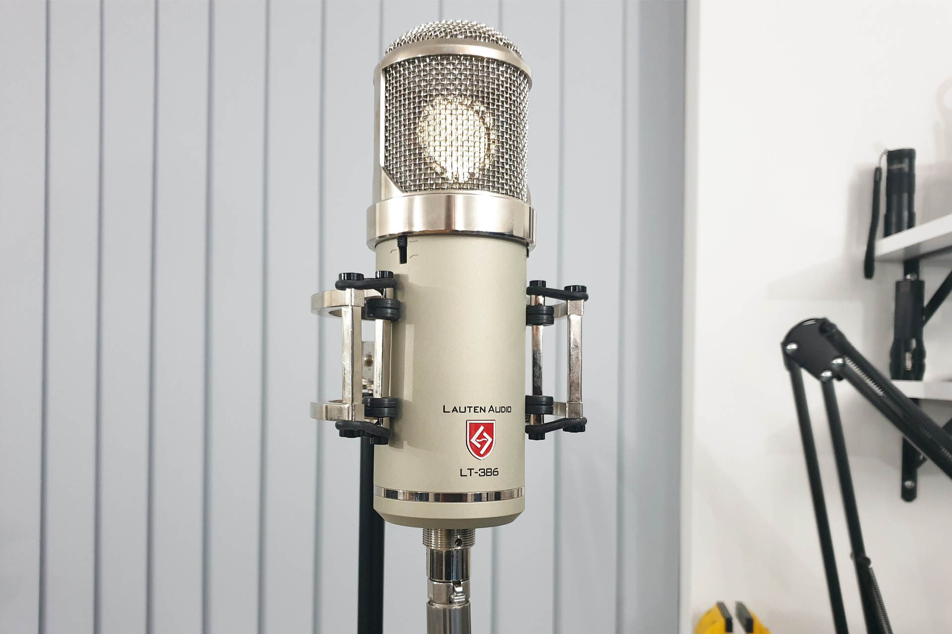
Here's my own Lauten Oceanus LT-381, my main vocal recording mic.
Occasionally, even the best large diaphragm studio condenser microphones might start playing up and with so little in these transducers that are at the very heart of our music, you may be puzzled as to why this happens. Well if you think about, you shouldn't be! Despite best efforts such as use and storage in a smoke, pet and dust free environment and the use of pop shields, being exposed to what comes out of people's mouths (!), what's behind that grill, inevitably gets dirty and so microphone capsule cleaning is required.
Anything electronic generates noise but the noise generated by microphones obviously should be a bare minimum. If however, you start to notice an increase in background noise, random pops, crackles, whistles or even explosions, if the sound of your microphone has changed and perhaps you're experiencing a loss of sensitivity and if you've checked all your connections and pre-amps and perhaps even changed the valve in your microphone if applicable, then there's a good chance that your capsule needs some attention.
Here's a recording I made of the Lauten LT-386 microphone I've got here today.
Dirty Capsule
Yes, I'm very quiet!
Apart from being littered with artefacts, some of which are quite dramatic, the microphone sounds dull. An acute loss of character and a compromised frequency response render this device quite unusable. 🙁
Before going anywhere near the capsule, I checked the electronics and changed the valve twice but there was no difference in the performance. The only option now was to look at the capsule, the component that actually captures pressure waves (sound) and converts them into an electric signal.
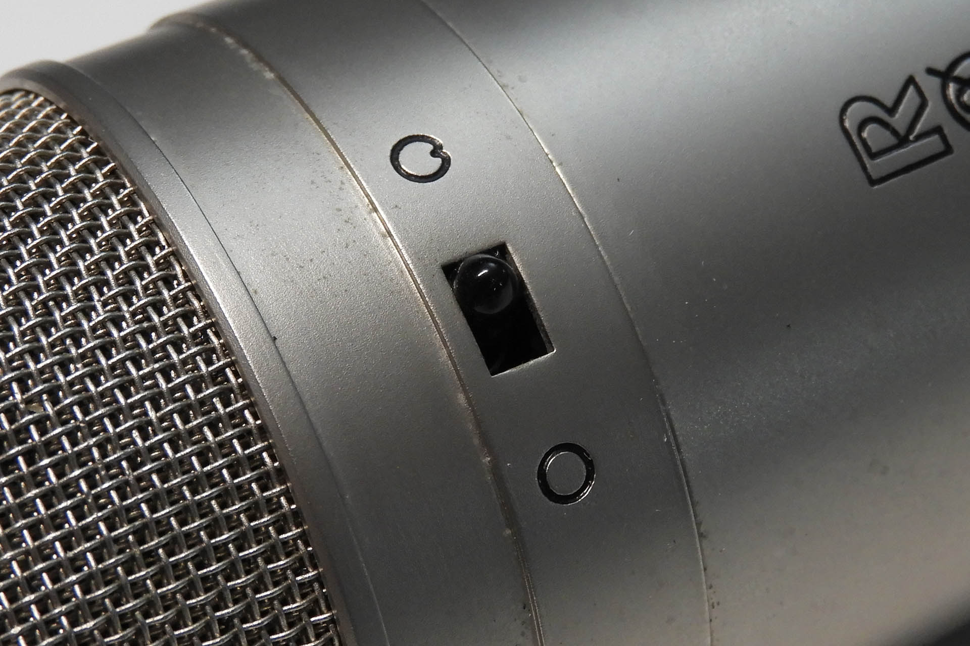
The first issue is getting to the capsule itself and some microphones are more difficult to dismantle than others. The well-known Rode NT2 (original version) for example, requires that the switches at the top of the microphone, be gently pushed in, so as to separate the internal top PCB from the top-grill, thereby exposing the capsule. I haven't found a way to avoid this and it's really a very worrying thing to do!
One of the switches on the Rode NT2 which needs to be pushed in to allow removal of the grill and access to the capsule. A popular nineties microphone but servicing the capsule isn't easy.
Thankfully, the capsule on today's microphone is much easier to access.
Once exposed, there should be either two or three wires coming off the the capsule which go into the microphone's on-board electronics. The capsule is normally secured in a cradle with a couple of screws, sometimes these screws are old-fashioned slot screws... yuk!!!! You really don't want to slip when removing them.
BUT WAIT!!!! It's not always necessary to remove the capsule. The objective here is to clean the capsule so on this occasion, it'll be staying in the cradle. YAY!!!
Microphone capsule cleaning is a daunting task, even for someone experienced like myself. It requires patience and great care. The surfaces of the capsule for example, shouldn't be touched although sometimes contact simply isn't avoidable. I'll elaborate later.
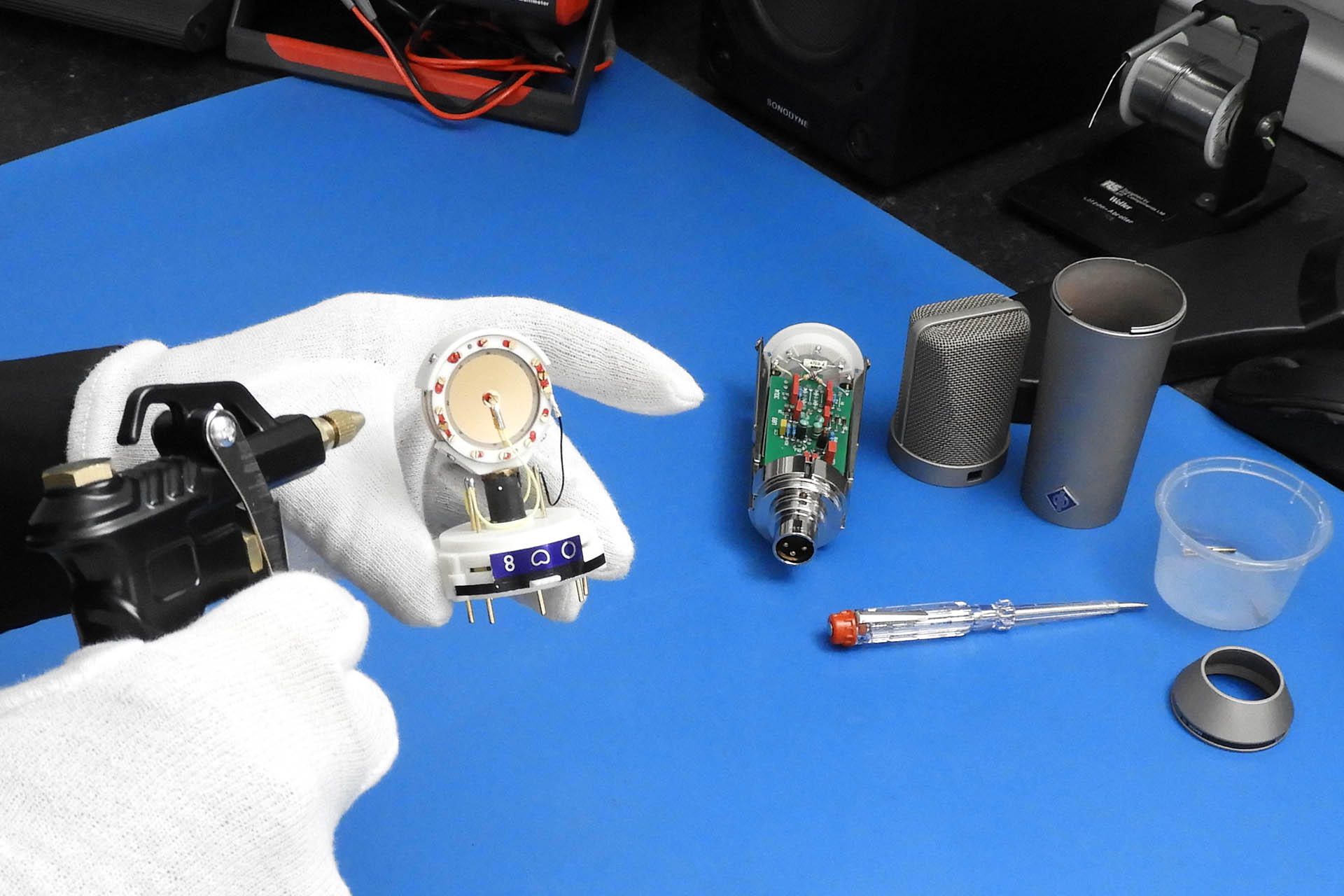
When handling delicate electronics, I always wear gloves, either lint-free antique document / photograph handling type gloves or rubber laboratory type gloves. I have to admit that I prefer the former when working with microphones.
These lint-free gloves are what I use for anything and everything that needs to be handled with care. They also prevent biological oil getting on to sensitive surfaces.
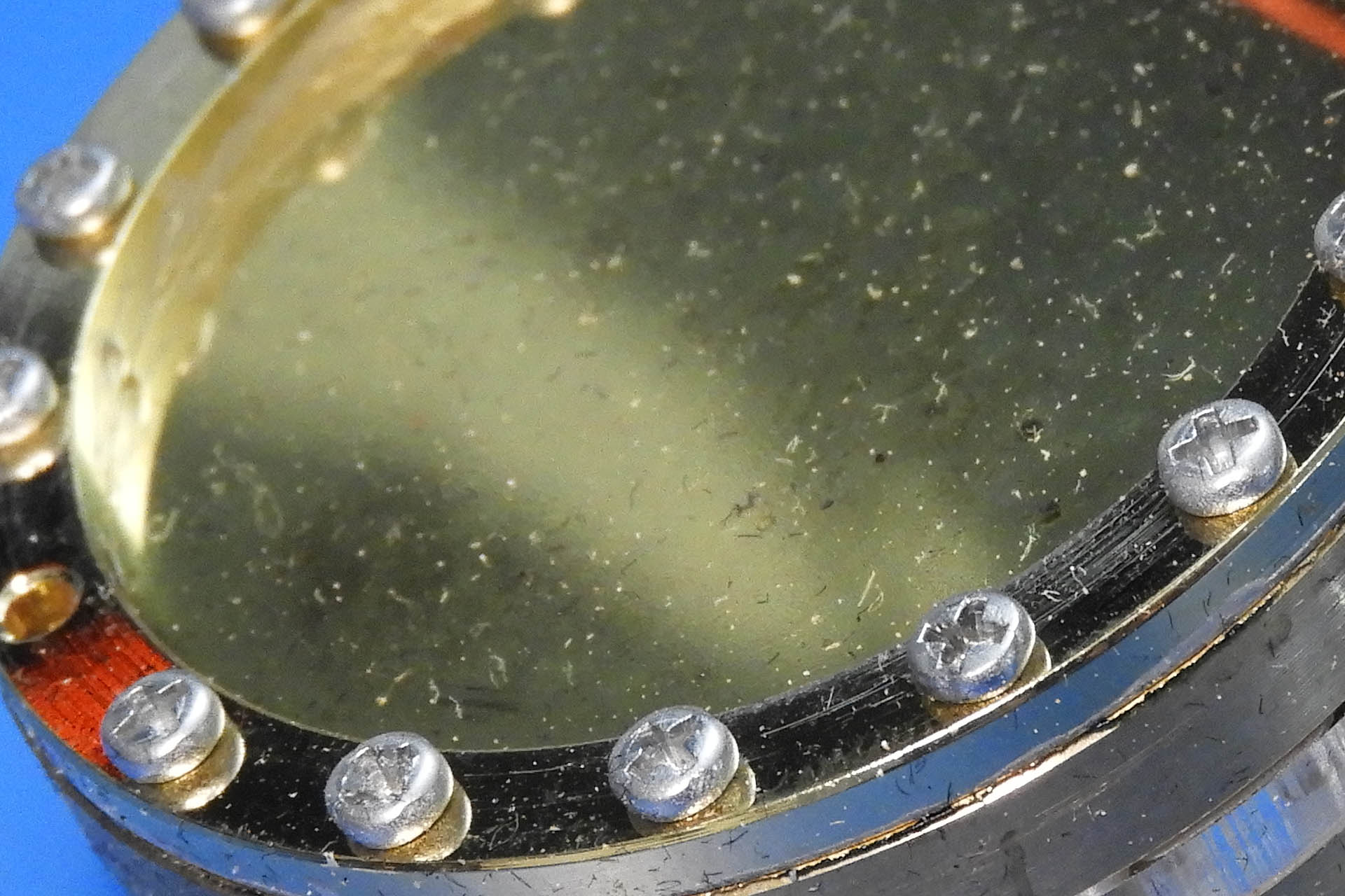
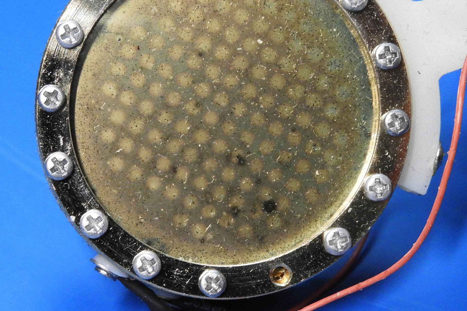
A close inspection of the gold sprayed diaphragms (both sides of the capsule), reveals a considerable amount of dust and other contaminants. Difficult to photograph, experience tells me that the surface isn't at all shiny as I'd expect and has a layer of 'greyness' over it.
Here's the capsule of the microphone I have in for repair, clearly showing a considerable amount of dust and dirt.
The other side of the capsule looks even worse, quite bad in fact. I hope those black marks aren't fungus! Yes, I've seen that one before. That shouldn't come as a surprise. As I said in the first paragraph, microphones are exposed to everything that comes out of our mouths. That includes bacteria and even viruses!!!!! 😷 😷 😷
Not at all sure what the black marks are on the other side of the capsule. Very worrying indeed.
Now I need to try blowing off that dust and dirt. NO, NOT WITH MY MOUTH!!!!! I use either a can of compressed air or my mini compressor which has a blowgun attachment. I prefer the latter as it delivers a consistent stream and is a little more controllable than a can. The air stream is directed at an angle as opposed to perpendicularly to the diaphragm.
So this time around, the compressed air got rid of most of the dust but I could still see dirt on both side of the capsule and those worrying black marks were still there. So now the tricky bit...
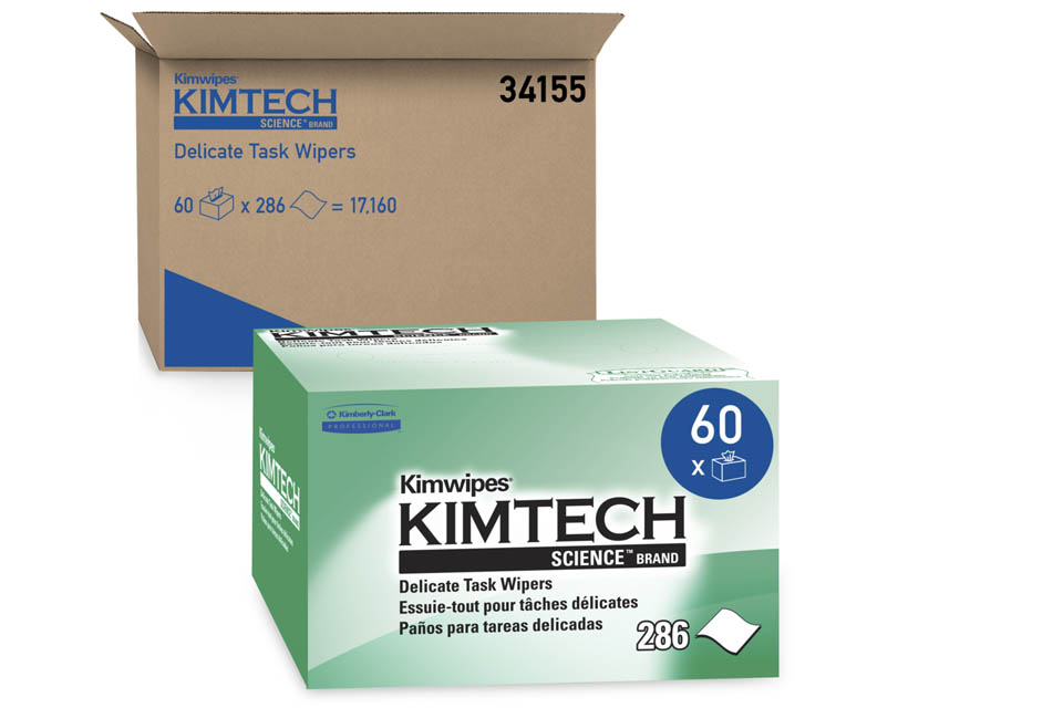
The next stage of the process requires that I make contact with the diaphragms and for this, I'll be using pharmaceutical wipes, Kimtech Kimwipes to be precise. A specific technique needs to be employed. The knack is to bunch up a corner of a wipe and stroke it gently and with minimal pressure, over each surface of the capsule. It's almost instinctive to put your finger behind the wipe as you would if you were polishing something but that's a seriously bad idea. Instead, I guess the technique is more akin to using it more like a cotton bud.
KimTech Kimwipes are ideal for this kind of job.
The Kimwipe clean had the desired effect and loosened up much of the debris allowing another gentle application of compressed air, to detach it from the capsule's surfaces.
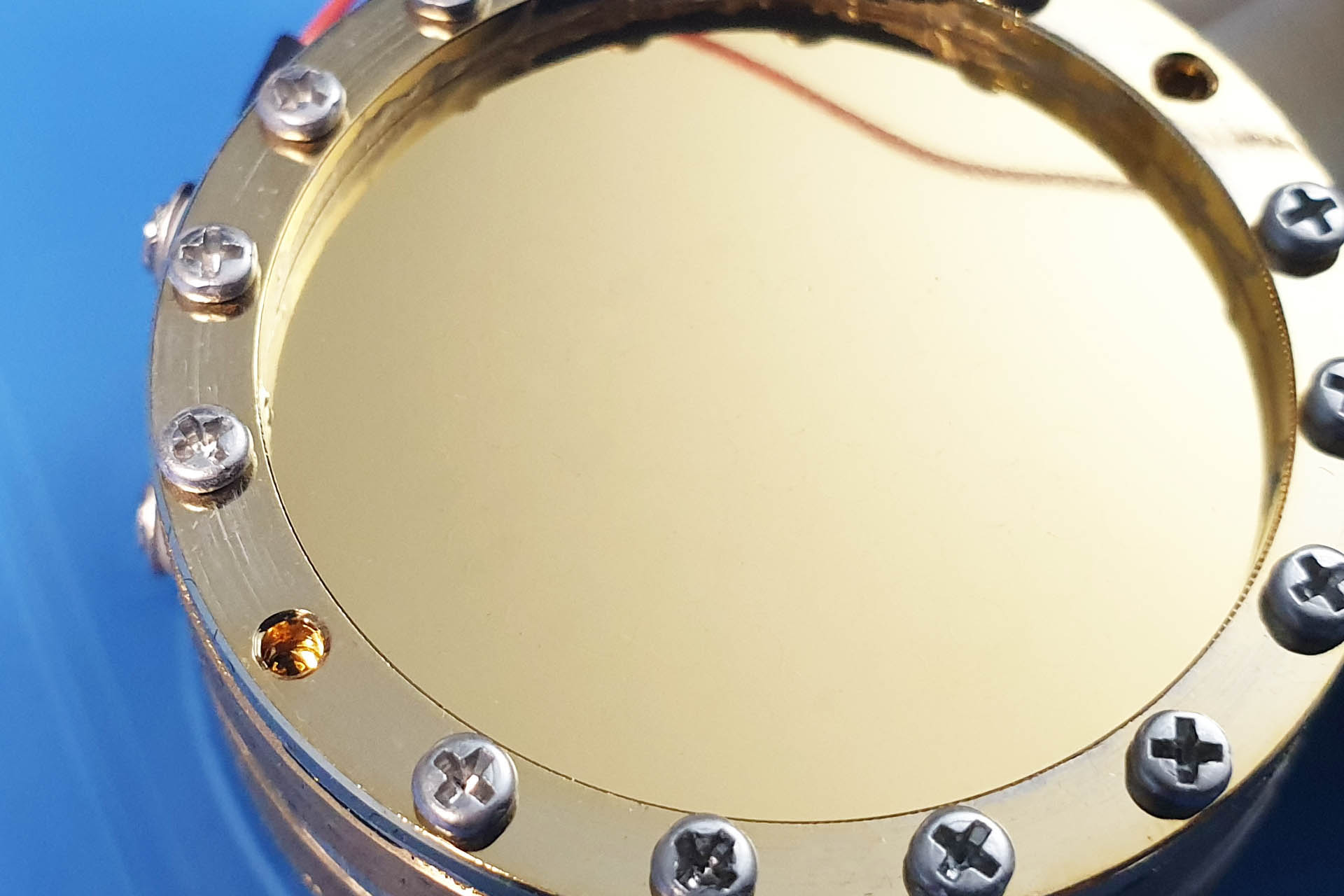
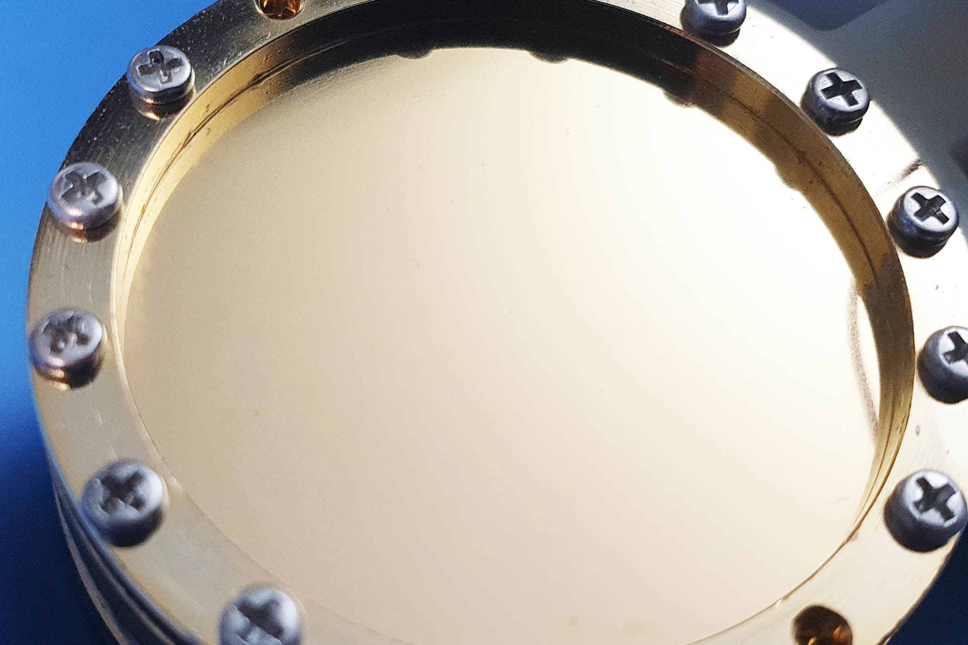
So here's what the capsule looks like after cleaning. It's so bright and smooth, it's actually making the screen on my laptop look bad!And here's the other side. As if by magic, those black marks have gone! The lines on both images are shadows of the capsule's wires.
Okay, so the capsule looks a lot better now, like A LOT better! You can actually make out the highly reflective gold layer. Now let's reassemble this mic' and check it out...
WOW!!!!! Not only have the pops, crackles, bangs, whistles and 'explosions' gone but the microphone actually sounds fantastic. It's amazingly more sensitive and there's so much more detail. Here's what the microphone sounds like now...
LT-386 Post Capsule Cleaning
Oh boy, doesn't that sound different?
I know you've been curious so now I'm going to tell you; the microphone I've been working on, is a customer's Lauten LT-386, an absolute stunner of a transducer. I have to admit that I really like the sound of Lauten microphones; sensitive, detailed, solid and crisp. Much of the character and nuance of any microphone is of course, subjective but the Lauten sound is right up my street! My own LT-381 goes into a SPL Gold Mike Mk II and with the 'Flair' function switched on, as well as cutting through, the results are just beautiful.
Despite the fact that this particular microphone has been stored well and used with respect by its current owner, the fact that it was purchased second-hand means that there's no guarantee of how it was used prior to entering the current owner's possession.
This Lauten LT-386 is now sounding like it should, smooth, rich, detailed and solid and doesn't it look cool.
Okay, now the give-away... I can't take all the credit for this one and many (MANY) thanks are due to Andy at Lauten Audio for his help. With Andy's words of advice and guidance, I'm delighted to have helped out one of my customers and particularly delighted to have given this beautiful microphone, a new lease of life. 😎
I hope I've got the message across by now; microphone capsule cleaning requires patience and care. The gold on the diaphragms is only a few microns thick and it's very easy to damage that so important layer. You definitely don't want to breathe directly on to the super-delicate diaphragms or touch them with your skin. Even putting the open microphone down on my workbench, needs to done mindfully. Basically, contact between the capsule and anything must be strictly avoided!
And finally... Lauten Audio has a reputation for appreciating its customers and is a very 'human' company to deal with. I've had long exchanges with Brian in the past and it's most reassuring to have such friendly, patient and helpful people behind these gorgeous microphones. With such a specialist task in hand however, Andy's in-depth knowledge and patient help was only offered due to the fact that Plasma Music Limited, has considerable experience of servicing albeit, mainly microphones of well-known European origin (yes, I've done some Audio Technica microphones, too). Plasma also has a long association with Synthax Audio UK, the local distributor. It should go without saying that manufacturers such as Lauten Audio do NOT recommend end-users carry out such procedures as described in this post and that only qualified and experienced technicians perform this type of dismantling and specialised cleaning.
UPDATE - 30th September 2022
Can you believe it? Someone contacted me yesterday, asking if I could help with a Neumann U87 that had gone noisy!
Not nearly as bad as the Lauten LT-386, this U87 was suffering from considerable self-generated noise and low-level artefacts, in particular a kind of rumble.
The diaphragms on the capsule were shiny. They looked nothing like the images of the LT-386 capsule above and just seemed a little dusty. In fact, I was quite surprised that this capsule was playing up. Then, using one of my magnifying systems, I noticed something that might have been causing the problem. There was a little spec of dust, grime or dirt that had got stuck between one of the diaphragms and the inside of the ring of the capsule. This would require a skilfully directed burst of compressed air. If I get this wrong, I could push that particle further underneath the ring.
Using the same technique as I did with the Lauten LT-386, I cleaned this Neumann U87 capsule which coincidentally, came in yesterday. Notice that the Neumann capsule is of a slightly different design to the Lauten.
Capsule cleaning is pretty nerve wrecking, even for experienced techs. This time, I got lucky and my aim was 'spot' on. 🙂
My own microphone collection includes a similar generation U87 so once I had tested the customer's example, I was curious to compare it with my own. Yep, they sound pretty much the same!
I've decided to document my exploits into making my own DIY acoustic panels in the hope that it helps other people who hate DIY as much as I do!
I wanted to take August off so that I could finish the studio and the rest of the new place but I had such a busy month. The 'busyness' continues so I have no option other than to squeeze finishing off things, in between repairs, service and mod' building.
I only have the lounge, two cloakrooms and the hallway to do but with people wanting to record here, I urgently need to finish off the studio part of the new house.
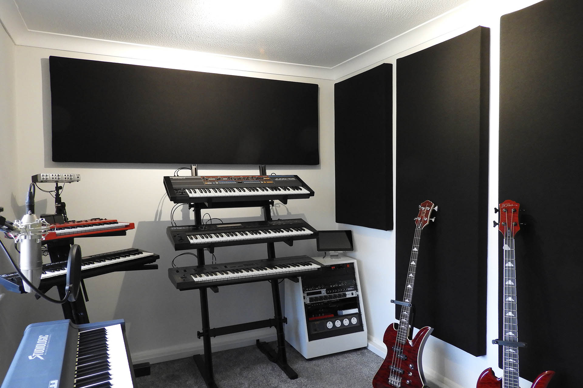
Everything's in place, wired up and working great. I just love the sound of well, everything! 🙂 I do however, have to acoustically treat three rooms; the mic room, the keyboard room and the control room.
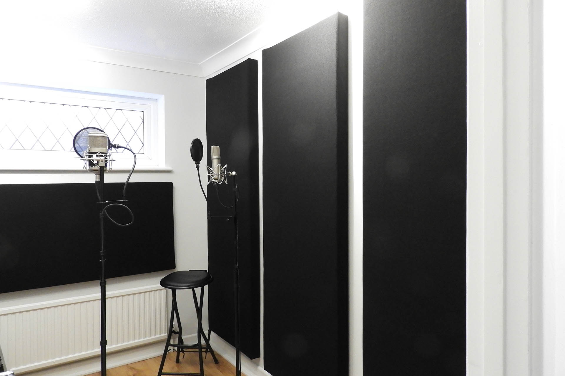
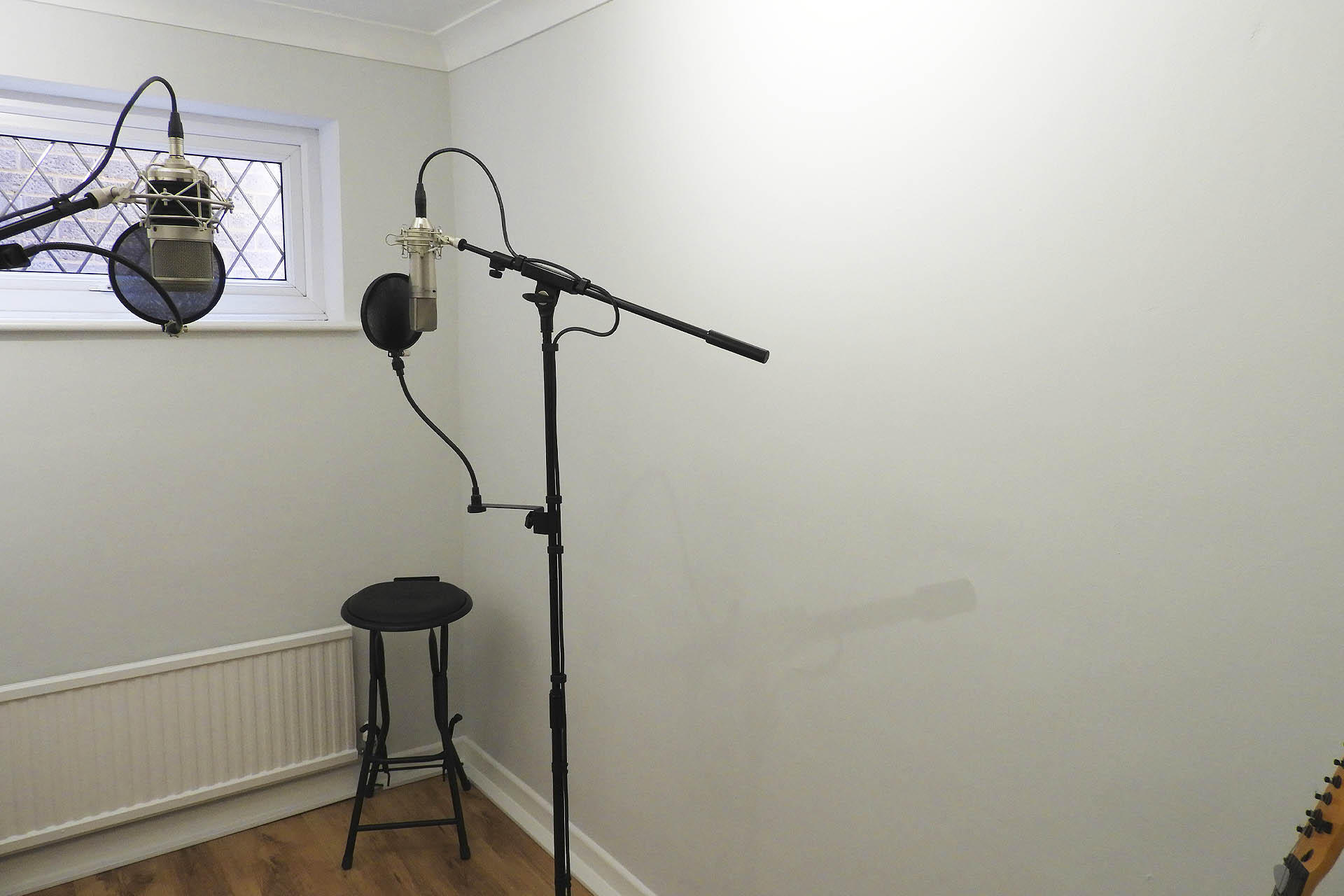
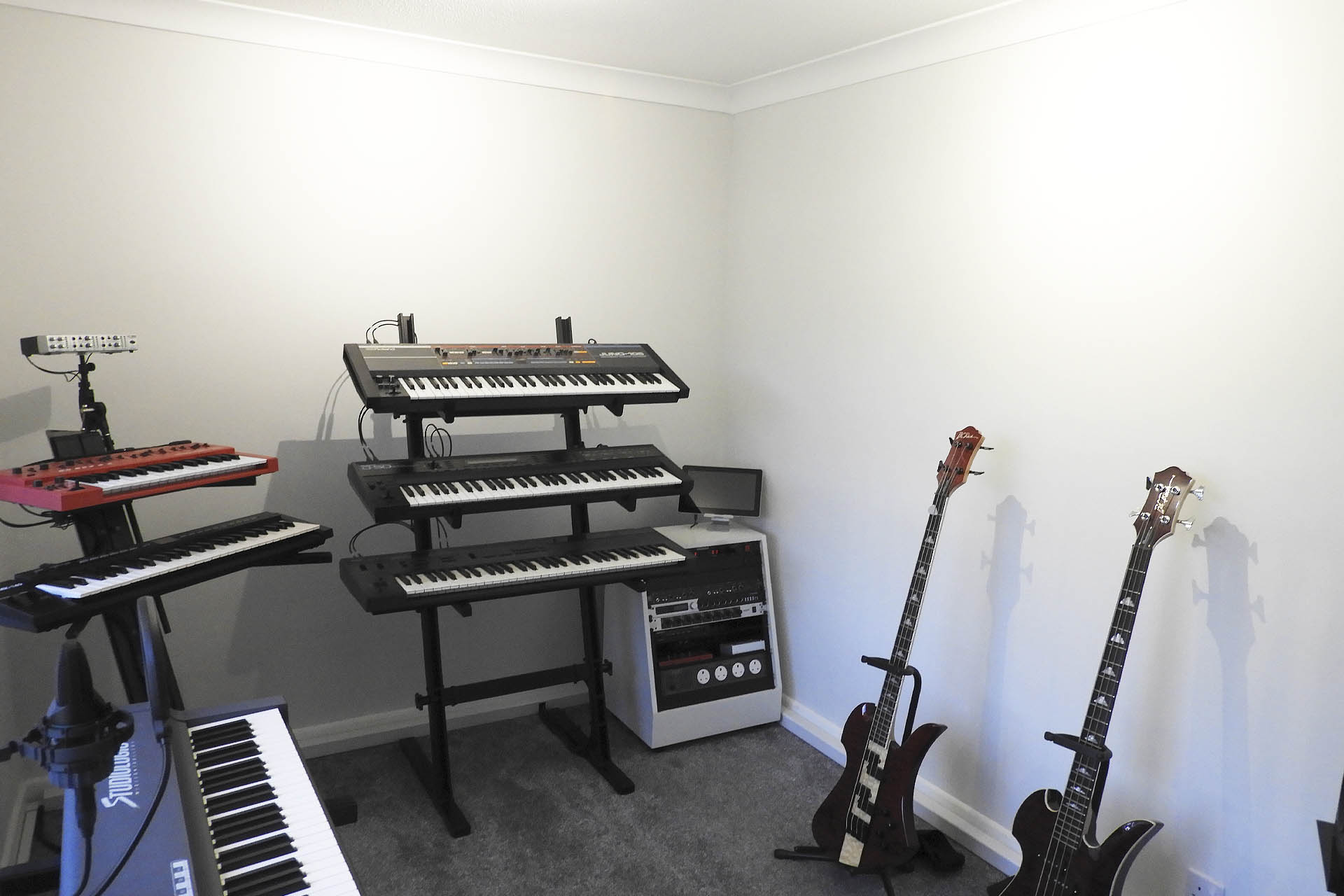
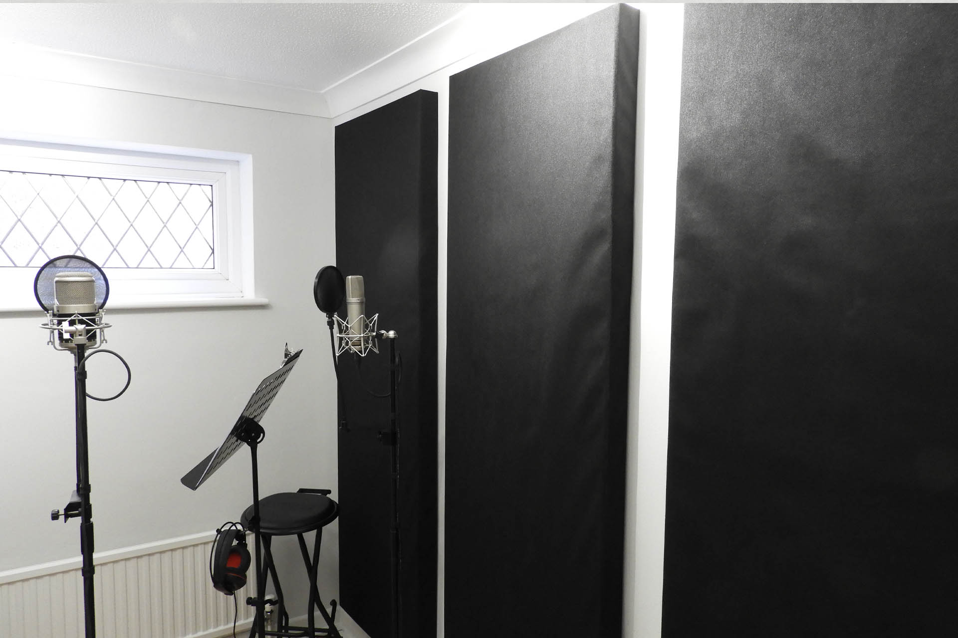
This is my mic room; a great space to record vocals and acoustic guitar that's well insulated from the rest of the house but which is in obvious need of acoustic treatment before I press the red button!
My intention is to mount three 2m x 0.7m panels on the wall pictured above and three 1.7m x 0.7 meters on the wall opposite. After doing some tests and experimenting, I know I'm going to need some smaller in-fill panels . There's also a 'spring' sound coming off that wooden floor. Anyway, I'm going to get the main six panels in place and take things from there.
I was going to do the 'lazy' thing and just glue foam tiles to the walls but I've always been envious of studios with those lovely looking acoustic panels. The new place looks fantastic and I feel that I should at least try to do it justice when it comes to acoustic treatment. Hence, I decided to do something stupid and build my own acoustic panels.
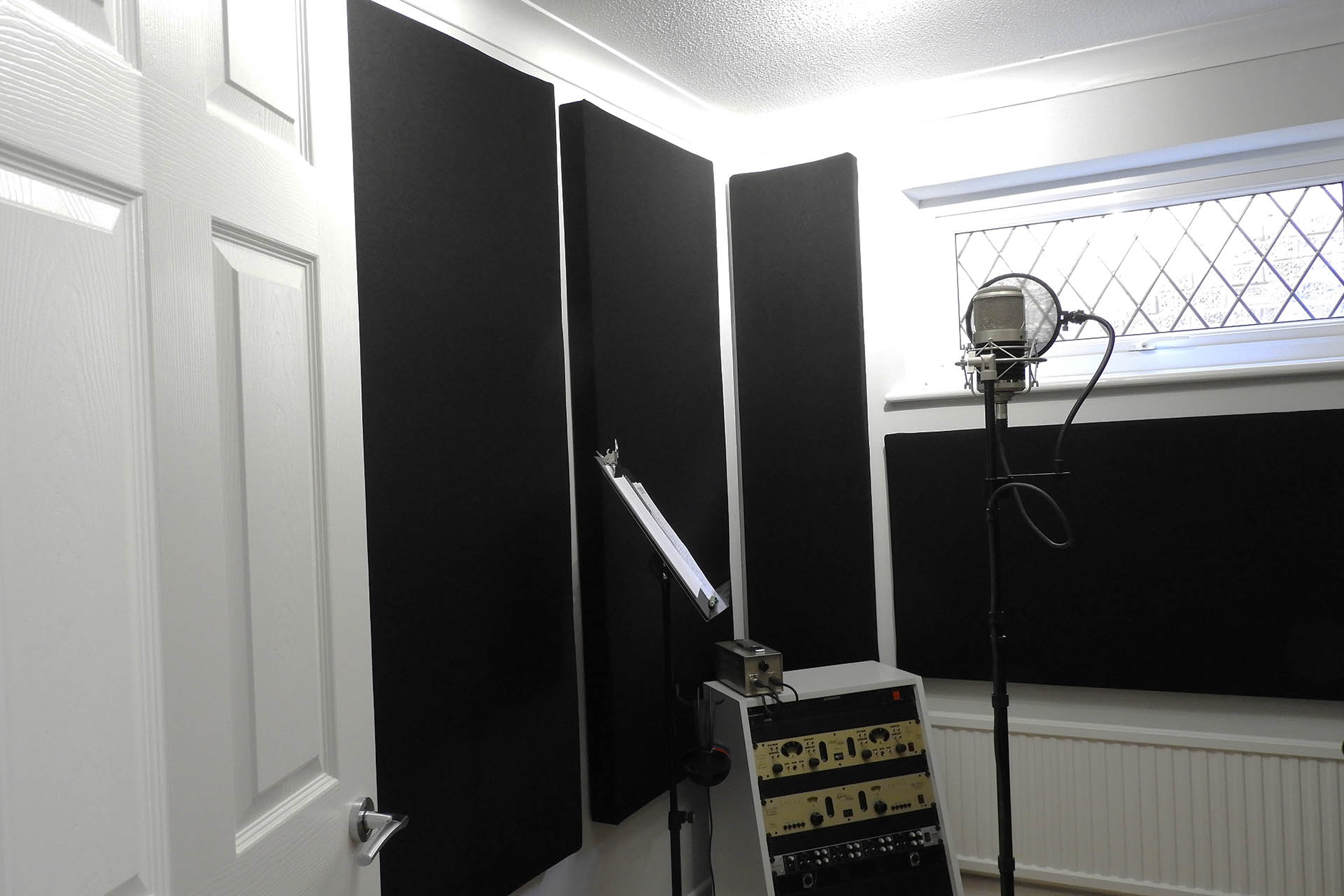
My keyboard room; I'll be recording vocals in here too, so way too much hard wall that needs 'softening'.
The wall behind the basses is going to get either three vertically mounted panels or two horizontally mounted panels. Once they're in place, I'll need to see if the area above the keyboards will need treatment. I think it might. 🙁
You'll recall from previous (DIY) posts, that I have a severe aversion to DIY but as has also been mentioned in those posts, "sometimes a man's got to do what a man's got to do..." Well, I didn't put it quite like that.
So, as you do now-a-days, I went on-line and found this excellent You Tube video which described in sufficient detail, how to make your own DIY acoustic panels. I thought it was great and it seemed that at last I'd found a resource which suggested that a DIY phobic like me, could actually do this. I studied it carefully and ended up implementing a few tweaks of my own. To prevent the cross pieces from twisting for example, I glued them as well as screwing them.
NOTE: After pricing up all the materials, I found that the unit price is nearer 60 GBP than the 25 USD mentioned in the video. Not a real surprise as prices of everything have shot up here in the UK, over the past few months. On top of that, I've priced up for slightly larger panels.
After deciding on placement, I measured up the three rooms and settled on two panel sizes; 2m x 0.7m and 1.7m x 0.7m. As suggested in the video, I'll be using Camira Cara acoustic cloth which is quite substantial so the final dimensions of the panels will be slightly larger than the frame sizes.
The reason I've got two different panel lengths, is that the 1.7m panels will offer a good gap on walls which have power outlets just above the skirting boards.
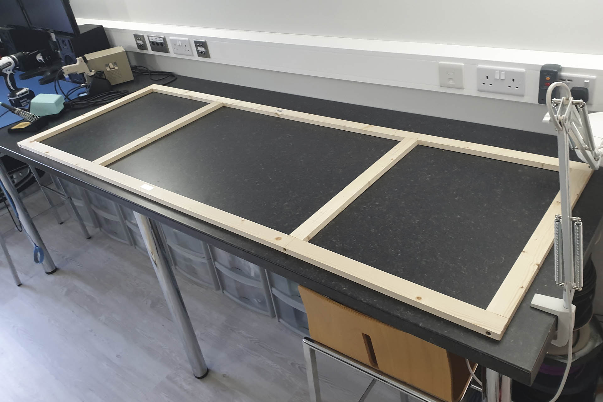
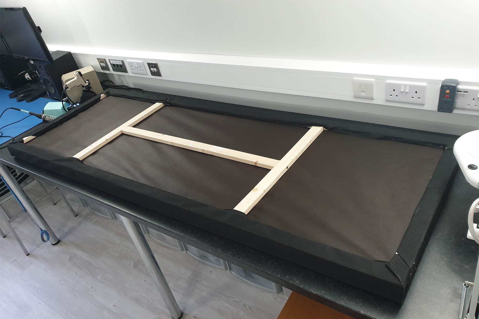
I started this post today and here's my first frame of twelve. This frame is for one of the 2m panels. Oh boy! What am I doing?
My first frame of twelve DIY acoustic panels. Note the addition of the two middle cross braces. A tweak over the frames shown in the video, I'm hoping that they'll improve structural integrity and offer more mounting options.
The wood is 44mm wide so I used M5 x 70mm countersunk wood screws and pre-drilled with a 2.5mm x 160mm drill-bit. Of course I didn't drill all the way to 160mm but that length seemed to be a standard size.
A WORD OF CAUTION... That's a long, thin and BRITLE piece of metal, so be careful! The reason I used a long drill bit like this, is because it has to go through 44mm of wood and then some more into the other piece of wood. There's no point in pre-drilling if you don't remove the wood so you need to extract the drill bit a couple of times when you're doing this but PLEASE take it easy. Don't push the drill bit. Let it find its own path.
The panels should of course, be at the same level when hung and I wasn't sure how I could guarantee that, implementing the picture wire and eyelets in between the upright struts method, as featured in the video. Varying tensions of the wires would surely mean that some panels would 'sag' more than others. I'm guessing that if I use longer eyelets, I can screw them further into the wood to increase the tension of the picture wire. Hmm... I guess I should get to the end of this and find out how much one of my bigger panels weighs. I can then suss out appropriate fixing hardware.
Anyway, if things go according to plan (yeah, right), I'll be adding to this post over the next few days. If your interested in making your own DIY acoustic panels, please stay tuned. I'm in the UK and have bought all the materials locally.
UPDATE - 16th September 2022
Originally I was going to cut all the wood for my DIY acoustic panels, make all the frames in one go, staple the backing on all twelve panels, etc, etc. Keen to see results as soon as possible, I then decided that I'd make these panels in batches of three. Unfortunately, there's been a hold-up with the foam and I have a few days wait, so I might as well go back to plan A.
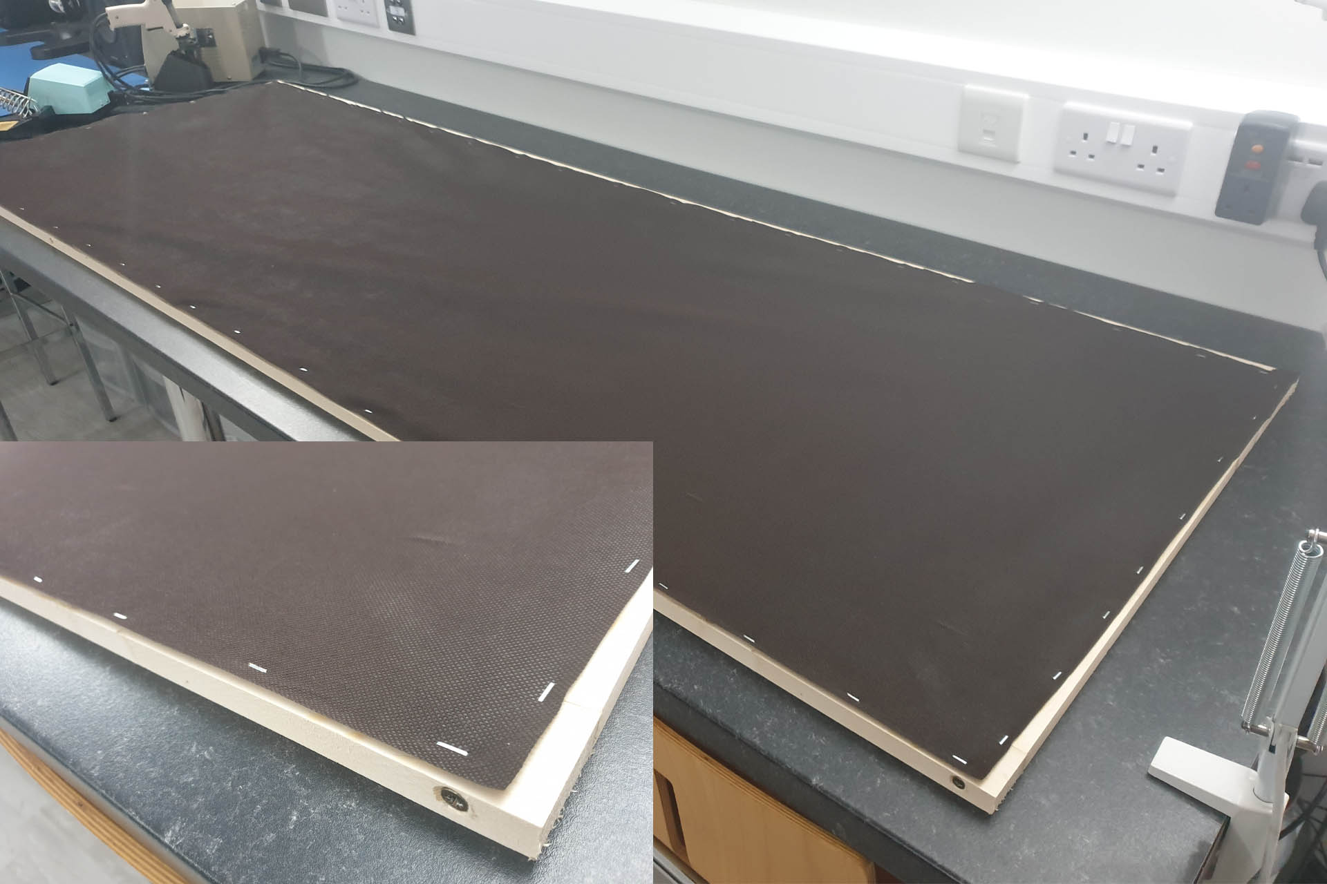
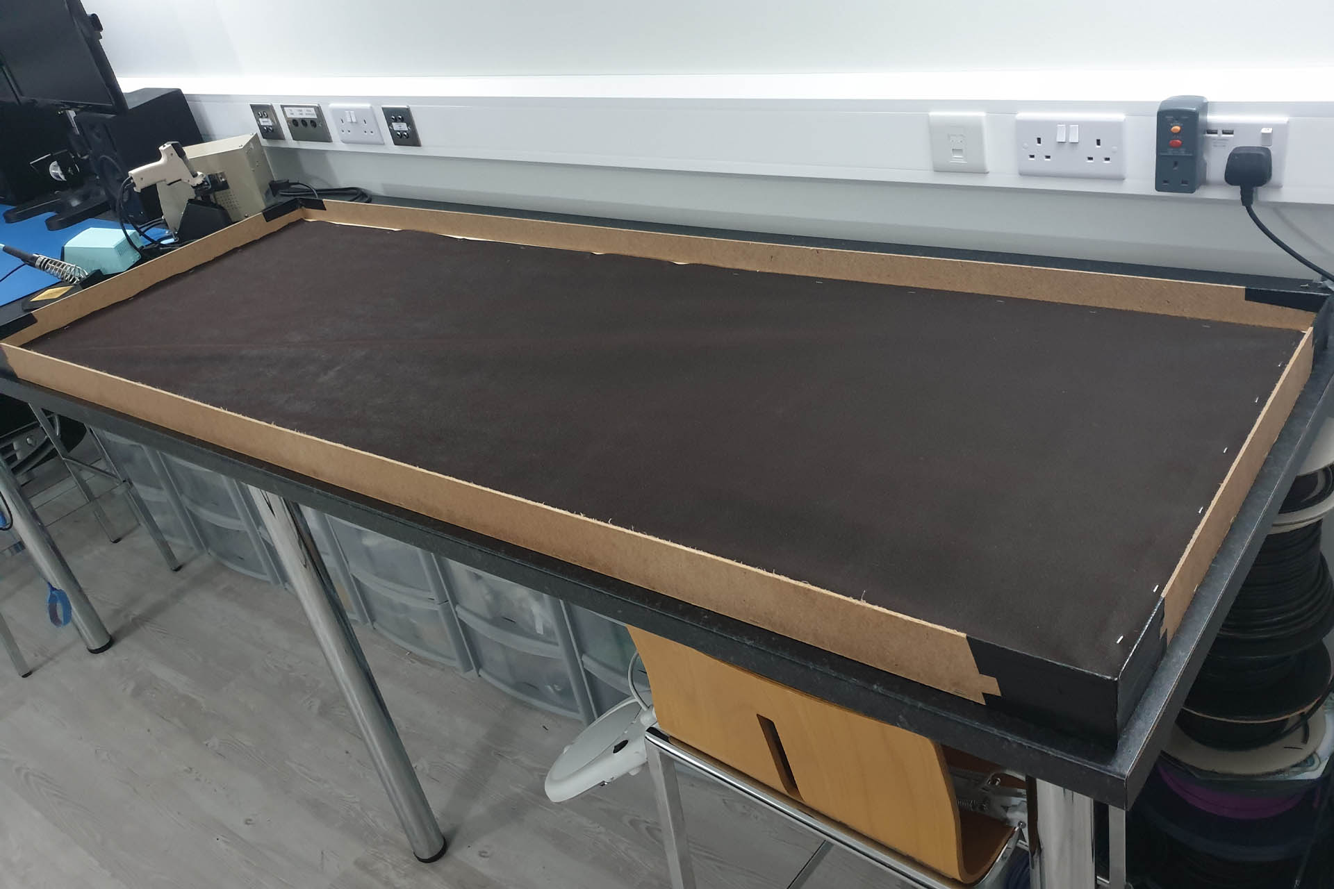
Having said all that, I thought I'd suss out stapling the weed membrane on to the frames so pictured below is a frame with just ordinary weed membrane stapled on to what's going to be the inside of one of the 2m panels. Keeping the membrane as taught as possible whilst stapling was a little challenging.
NOTE: I said 'ordinary weed membrane' but it's not as simple as that! There are several types of membrane which can be put into one of two categories; a very plasticky type and another that's more like a fabric textile. The former while cheaper, is more difficult to work with, frays quite a bit and I doubt that it has any suitable acoustic qualities. After trimming, you'll have a lot of plastic bits to clean up. The slightly more expensive fabric type (that's shown in the video) is easy to work with and gives a super smart finish.
Hey, I haven't finished yet! You then need to look at the 'gsm' specification or 'grams per square meter' which should be between 80 and 90. You can get membrane which is like 50 gsm but you can pull it apart in your hands which is useless.
Inset is a close-up of the more expensive membrane showing a nice clean-cut edge that doesn't fray and that's been stapled.
The first reel of membrane I bought was Gardman WeedStop Performance 75617. This was the last roll that the local Hillier Garden Centre had so I then went to B & Q and bought a 30m reel of Verve Performance Weed Control Fabric.
At this stage, I'm reluctant to buy the hardboard for the external perimeter as I want to lie the foam on top of a panel to check the overall height and hence, the height that the hardboard should be. The foam supplier is short of 40mm foam in the density I've bought and has offered me 50mm instead, for the same price. The thickness of the wooden frame is 17mm, so the hardboard will theoretically be either 57mm or 67mm (theoretically). Another wait. Grr...
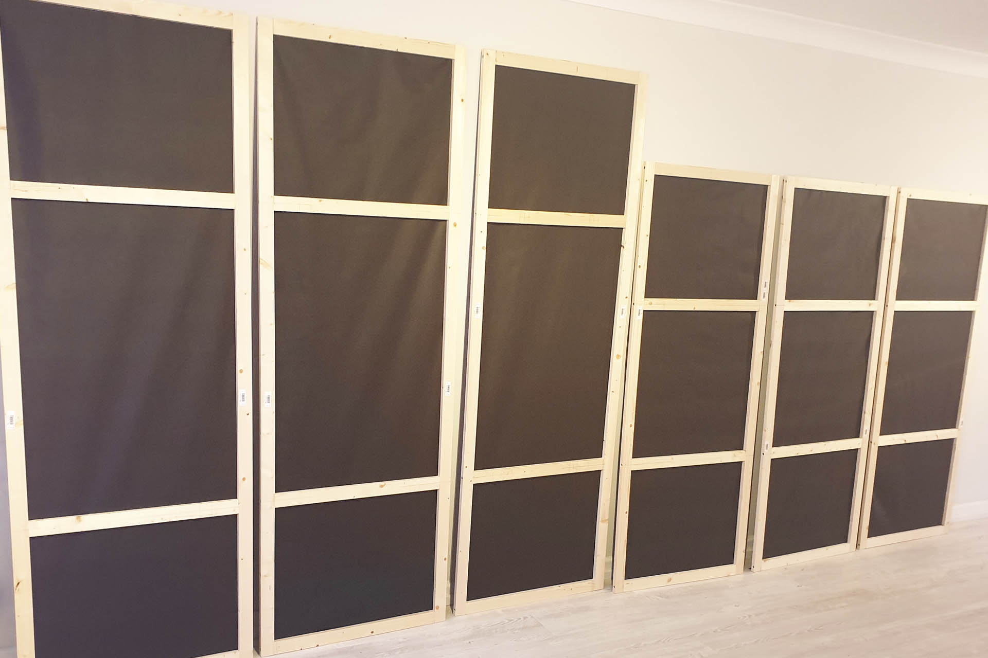
I've now made the frames for the six main panels for the mic. room; three 2m x 0.7m and three 1.7m x 0.7m.
Six frames for DIY acoustic panels for my mic. room. Three are 2m x 0.7m and three are 1.7m x 0.7m. The membrane side will actually be facing the inside of the panel. What you're seeing, will be the rear of the panel.
At the end of the day, I contacted the foam supplier and told them that I've decided to go with their offer of the thicker 50mm foam. I've still got a few days wait before it arrives. Time to get on with a few repairs, I guess.
UPDATE - 22nd September 2022
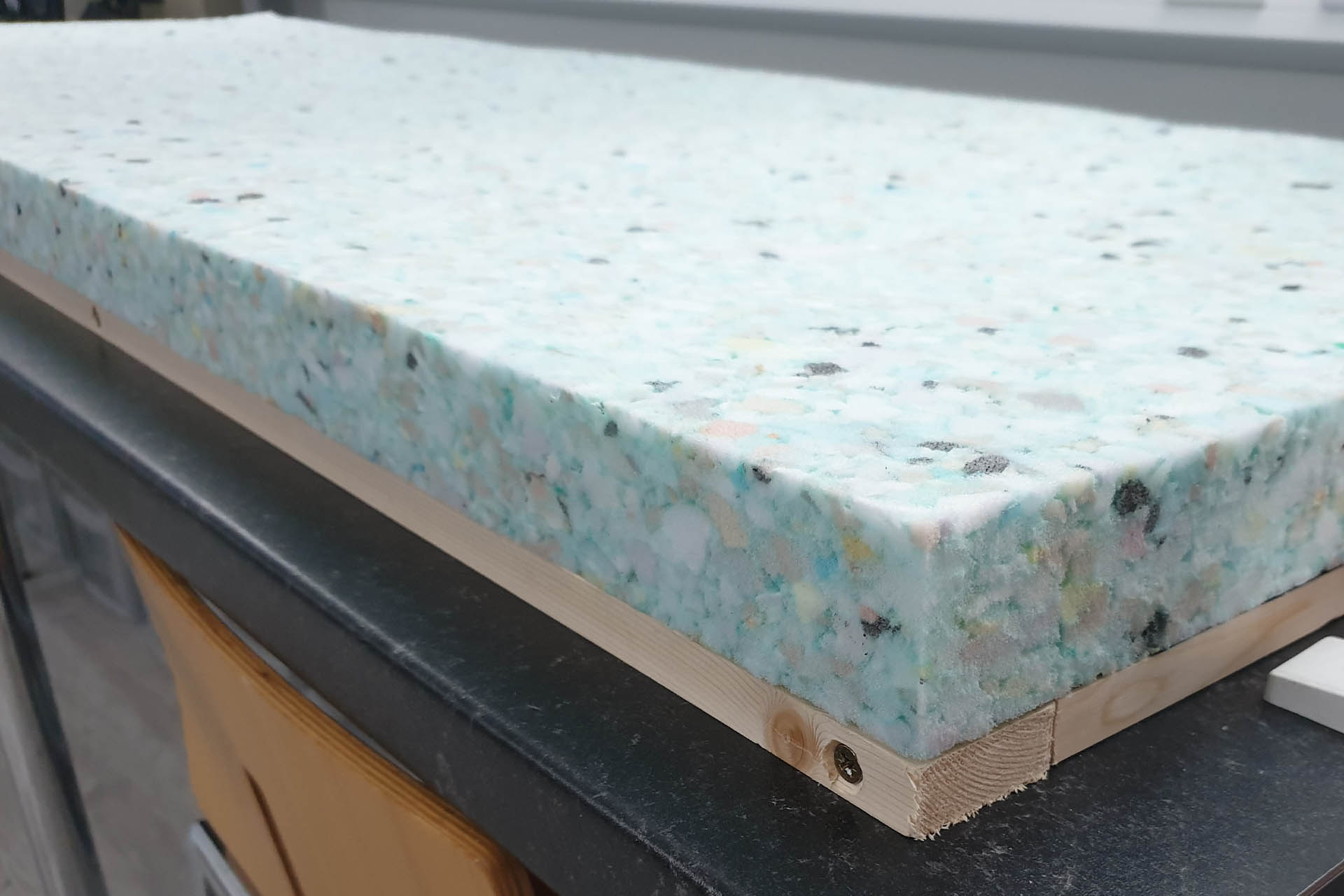
Six days, yes SIX days since my last post and the foam has finally arrived. It's a lot heavier than I expected!
Here's a slab of the 50mm foam. This is 4lb recon foam with a density of 64kg/m³. A little arithmetic indicates that a 2m x 0.7m slab will weigh about 4.4kg and a 1.7m x 0.7m slab will weigh about 3.75kg. Heavy stuff!
Remember earlier that I mentioned I'll wait until I can place a foam slab on to a panel frame so that I can determine the correct height of the hardboard? Well, the theoretical height with 50mm foam and 17mm planed wood is obviously 67mm. 2mm can easily be absorbed so I'm going to get the hardboard cut at 65mm.
Selco cut as many 65mm strips as they could, out of a single 2.4m x 1.2m sheet of 3.2mm standard hardboard and I trimmed them down to size when I got back to the studio.
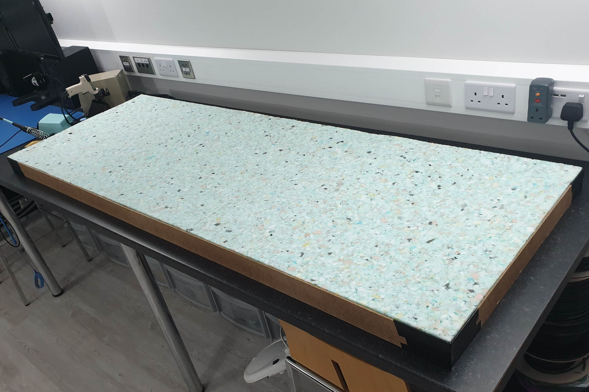
Pictured is one of the 2m panel frames with the hardboard perimeter attached. Notice that I've covered the corners with cloth tape as per the video.
I should mention that I had to hammer some of the staples in as the staple gun didn't always punch them all the way in. Both the staple gun and the 14mm staples were made by Stanley which is a name I've always trusted. I don't think this is a particularly difficult job so I was quite disappointed, to be honest.
The 2m foam slabs fit perfectly although I'll have to cut three of them down for the 1.7m panels. This could actually be a good thing, leaving me the option to make some very small panels.
Although the least dense available from the retailer, the foam I'm using is actually very dense for the job in hand. It's quite difficult to see in the above image but the foam sags in between the centre cross struts. This kind of pissed me off but then I realised that the panel won't be lying like this. It'll be mounted vertically on one of its edges. When I took the panel off the workbench and stood it up, the foam was fine (phew).
A WORD OF CAUTION... The foam stinks! I attached the hardboard perimeters to the three 2m panels quiet quickly and then called it a day. When I came back the next morning, the downstairs of the house stank. I opened all the boxes in which the foam was packed, took out the foam and left it to air for a few days. If the smell doesn't disperse, I might try an odour-killer. I'll keep you posted.
Now I need to get some more membrane prior to the front layer of acoustic material going on.
HEADSUP - I've quoted the hardboard as being 65mm high. The guy who cut it, actually did so nearer 60mm. This worked out better because it gave a slight bevel to the edges of the panels. I only realised and hence appreciated this, when I got my second lot of hardboard cut for the acoustic panels destined for my keyboard room. These were cut at exactly 65mm and aren't as nice as the first lot I got done.
UPDATE - 23rd September 2022
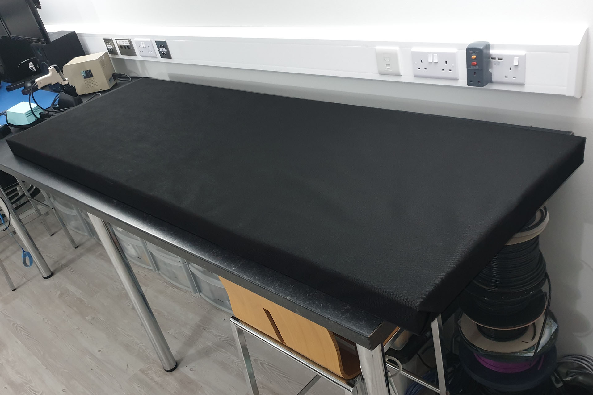
I couldn't find Gardman WeedStop Perfromance anywhere locally so I bought 30m of Verve 80 gsm from B & Q. Here's one of the large panels with the front membrane covering.
DIY acoustic panel with membrane covering. This doesn't have to be tight and perfect as the acoustic cloth still has to go on top.
You want to do the neatest job you can but remember that this layer doesn't have to be cosmetically perfect! The Camira Cara acoustic cloth is going over the front membrane. In fact, putting this on is great practice for applying the final layer. On the other hand, Camira Cara acoustic cloth is very expensive so if you're not too fussy about looks, a little practice getting this bit right and you could get away with just the membrane covering. Perhaps try applying a second layer? Of course, colour options aren't as diverse and with the weed membranes I've specified, you'll be stuck with either dark brown or black. 🙁
All six DIY acoustic panels now covered with weed membrane. Once I got the hang of it, this stage just happened.
I have to say that this weed membrane is great to work with. I covered all six panels quickly and couldn't wait to get an average weight of the three larger 2m panels. Oh dear! These things are coming in at like just over 8kg, much more than I anticipated and I still have the acoustic cloth to go on. I mentioned earlier that once I established weight, I could begin looking for fixing hardware which is what I'll be doing over the weekend.
MISTAKE... So it just occurred to me; my panels are 70cm wide and 7cm thick. The Camira Cara cloth is 1.7m wide. Hmm... I won't be able to cut the width of the cloth in half as 85cm (half of 1.7m) isn't going to stretch over the width of a panel and over the sides to leave enough to tuck in around the back. Oh BUM!!!! Even if the panels were 60cm wide, that would only leave 5.5cm on each side, to go around the back. The wood is only 4.4cm wide, leaving a centimetre to play with but it's still too close for comfort, especially for a DIY phobic like me. 🙁
See you soon...
UPDATE - 25th September 2022
I bought some Febreze Fabric Freshener today and I have to say that the awful smell of the foam doesn't seem so bad after applying this stuff. I'll buy another couple of bottles and see how it goes.
Also, remember I said that the weight of the foam was making a 'dip' in the middle of the panels in between the cross braces but after standing a panel upright on its end, the foam falls forward slightly so I didn't think it would be a problem? Well, it was really, really bugging me (like some things do) so I've put in a centre piece of wood on the back of each panel frame so that the foam now sits flat.
I decided to fit an additional brace to stop the heavy foam sagging in between the two centre cross braces.
UPDATE - 29th September 2022 - CAN'T SEE THE WOOD FOR THE TREES
While I'm waiting for the Camira Cara cloth to arrive, I've been giving some thought to how I'm going to hang these panels.
My wife Julie isn't musical at all and doesn't know much about the detail of what I do but... she's a great listener and brilliant for bouncing ideas off. The other day I showed her what I'd been up to and while describing the issue of hanging the panels, it came to me...
Remember those cross braces on the back of the panels? Well, they're very straight, 530cm and dead parallel to the shortest edge. If I just fix two screws per panel into the walls, then I might be able to simply hang the panels on the screws. Any height differences would be easy to fix. With a little packing on those cross braces, I can quickly and simply adjust the height of a panel, or straighten it if it doesn't quite look square. With this method, the panels can also be nudged horizontally so as to ensure an even gap between them. The solution to hanging my DIY acoustic panels was right in front of me all the time.
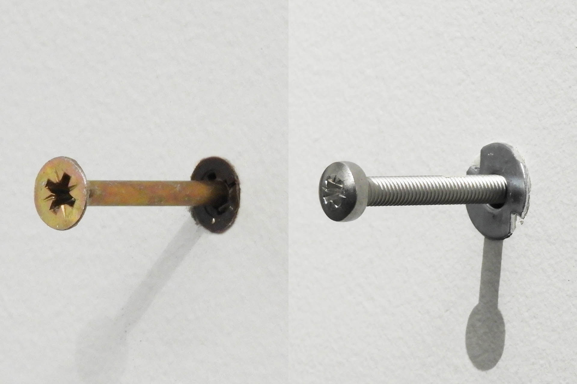
I used rawl plugs and M5 x 80mm self-tapping screws into the brick wall and hollow wall anchors and M5 x 80mm machine screws into stud wall.
It didn't take long to measure up, drill a few holes and try out my idea. Oh god, I'm lying!!!!! One aspect of DIY that I really, really hate is dust and it took me ages to move gear that I could move, out of the room and cover gear that I couldn't.
Anyway, in the brick wall, I used rawl plugs and in the stud wall, I used heavy-duty hollow wall bolts, the kind that require a setting tool. All screws were M5 x 80mm, providing a good length of screw in the wall with between 20mm and 25mm sticking out, on which to hang the panels.
As you can see, one or two of my screws don't appear to be quite perpendicular to the wall but as I keep on saying, I'm crap at DIY. Joking aside, you'll see later that small defects like this, won't make too much of a difference when the panels go on.
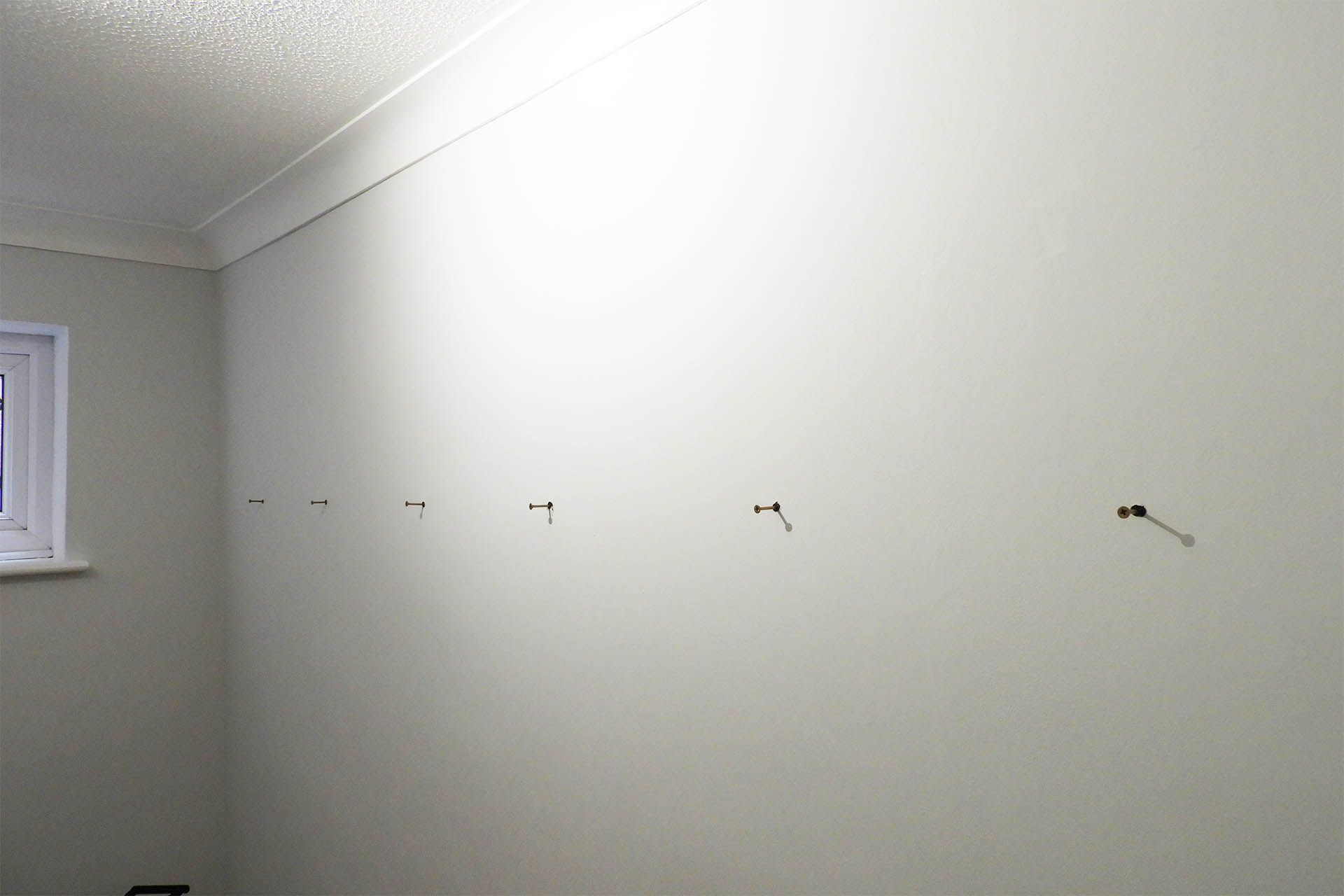
Two screws per panel is not only secure but offers an excellent degree of flexibility. The cross braces on the panel frames are 53cm down from the shortest edge. The screws are mounted 62.5cm from the bottom of the coving. This leaves about 7cm clear, at the top and bottom of the 2m panels.
So, although the panels are waiting for a final layer of acoustic cloth, they're in good enough a state to hang and allow me to conduct further tests of the mic. room's acoustics.
It's one thing clapping your hands and listening but really a microphone needs to be switched on and headphones worn.
I'm still getting that springy type of reflection and putting some rugs down on to the floor confirms that it's not just the walls that need treatment. Once I've got the walls under control, I'll need to look at that floor. In fact, I already have some ideas.
While I wait for the Camira Cara acoustic cloth to turn up, I just thought I'd test my fixing idea. Coolamundo!
Although faint, I'm now left with a very tight bounce in the high-mids. When I say 'tight', I mean that the delay of the reflections is extremely short, more akin to a flanger with the modulation turned off, than anything else. This is actually quite common in smaller spaces with hard opposing walls. Anyway, I have an idea where this is coming from and a little foam propped up against certain parts of the window wall and the door wall (opposite), quickly kill it. I now have an almost quiet room and more importantly, I know for sure that I'm going to have to make four or five smaller in-fill panels. 50mm foam would be excessive for these so I'll be using 30mm foam.
HEADSUP - It would be quite expensive to buy all the foam in all the pre-cut sizes that you might need. Although I had an idea, I didn't yet know the exact dimensions of the in-fill panels I was going to end up making so inevitably, foam will need to be cut! 🙁
The factory (foam supplier) uses a bandsaw. I can't imagine too many producers, audio engineers or musicians having one of those lying around. The next best thing (when you think about it) would be an electric knife and indeed an old Kenwood thing we had in the kitchen which never gets used, was just perfect. With virtually no foam dust, the electric knife cuts through foam beautifully and if you're patient, you can get a lovely smooth and more importantly, straight edge.
If you don't have one, consider splashing out. You can pick one up for reasonable money... and it might come in useful at Christmas!
If you're on a tight budget, then I recommend a bread knife. Start cutting the foam as if you were scoring it but with a nice, easy sawing motion.
UPDATE - 12th October 2022
It's almost a month since I started this project and I'm a little disappointed that it's all taking so long. On the other hand, there's been a lot of annoying waiting for stuff like foam and acoustic cloth, to arrive.
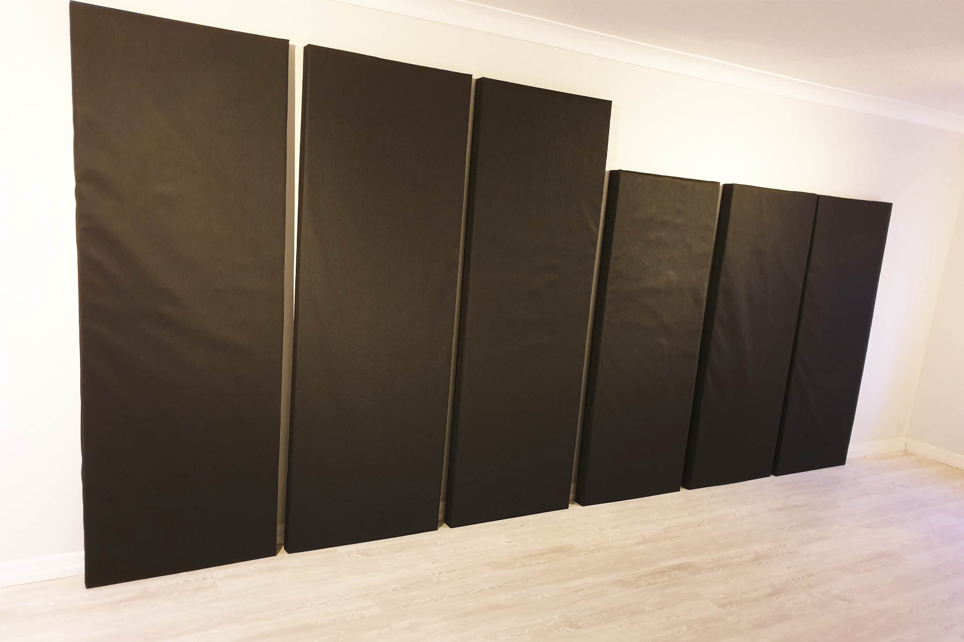
Anyway, the Camira Cara turned up and the fully covered DIY acoustic panels do actually look really good. Comparing the picture below with the previous picture, you can blatantly see that the acoustic cloth finishes the panels nicely and for example, doesn't have the same sagginess as the membrane.
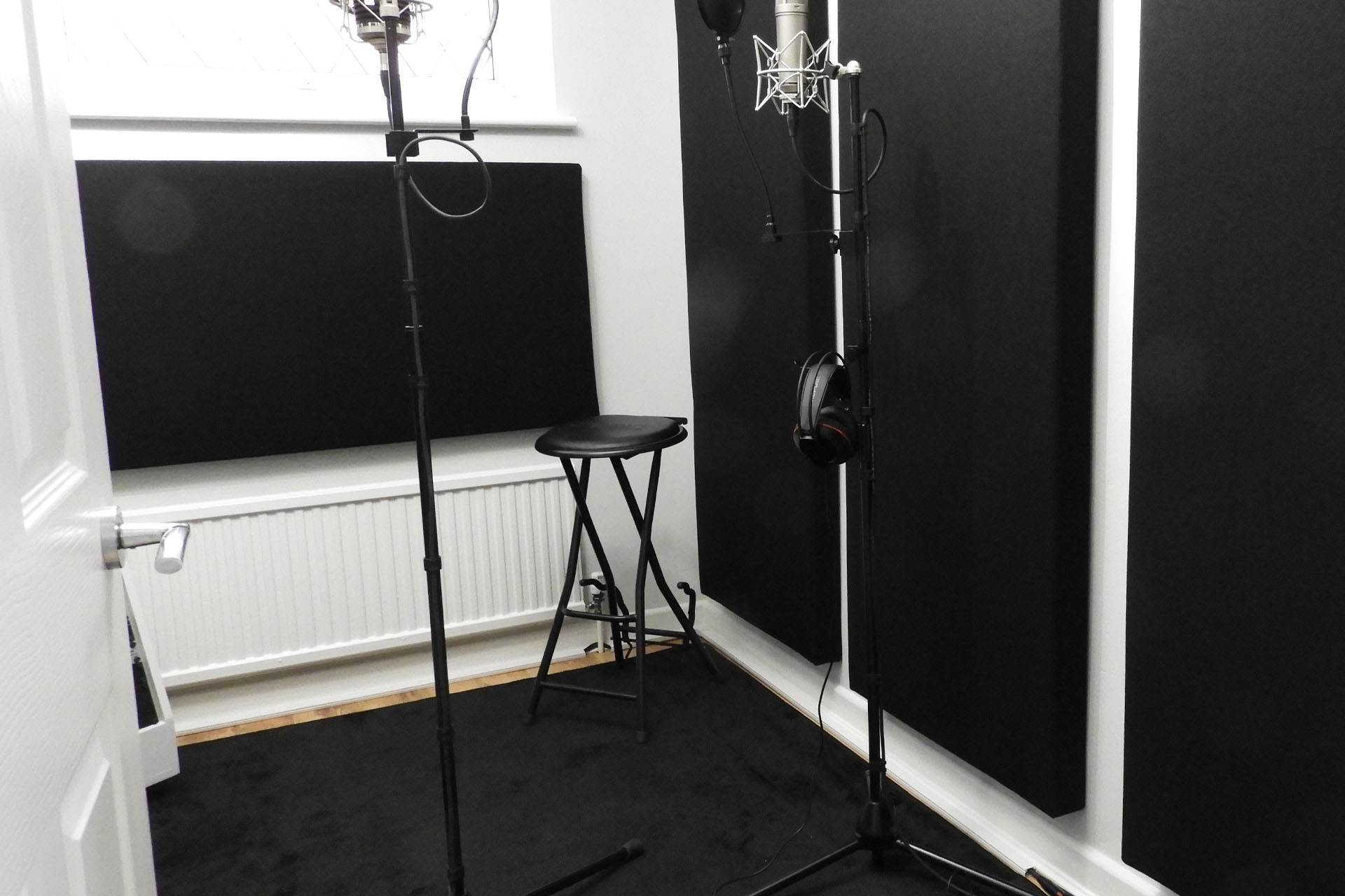
At last! Not only are the main DIY acoustic panels up but I've almost got the smaller in-fill panels all done, too. Check out the panel in between the top of the radiator and the bottom of the window.
With a little time on my hands, I made five smaller in-fill panels which were 45mm (with 30mm foam) high and not 70mm (with 50mm foam) high as the ones I've already made. And guess what... yep, I had to wait for the 30mm foam to turn up. Oh boy!
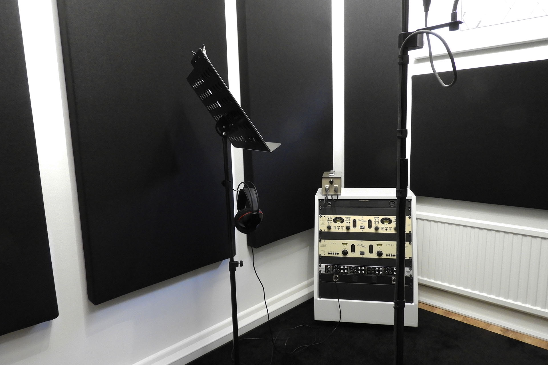
And here's the opposite (stud) wall. Some environments are quite difficult to photograph, especially when you want to highlight a specific feature!
UPDATE - 18th October 2022
So all the panels, including my in-fills, are up in the mic. room. My lovely rug arrived from Germany today and... I'm still getting a slight 'doing'.
I put some hard foam in front of the radiator. I put some hard foam over the window. I even covered the small bit of wooden floor that was still exposed. SERIOUSLY?!?!?!?
Then I turned towards the left wall and clapped. Then I turned towards the right wall and clapped. The bounce was only noticeable when facing the door. Then I covered the door and... GONE!
That surprised me but hey. Tomorrow I'm popping up to Studio Spares and buying three 600mm x 600mm, 25mm think panels that I'll glue on to the mic. room side of the door.
CONCLUSIONS
Firstly, I'd like to thank Michael for his excellent and very inspiring video. As I mentioned at the beginning of this post, I wouldn't have even attempted this if I hadn't stumbled across his video.
Now then, if I'm honest, buying some really nice acoustic foam tiles would have been much cheaper and I could have finished my mic. room in a day and my keyboard room and control room in another day but... you have to compare like with like and I've already mentioned how proper acoustic panels just look soooo much nicer than foam tiles!
Buying panels, let alone custom sized panels, would have cost quite a bit and making them yourself, is definitely cheaper. On the other hand, I'm more than a month down the line and while I've now made the panels for my keyboard room as well as my mic. room, I still have three or four panels to make for my control room. IT'S A LOT OF WORK, especially for a DIY phoebe!!!!!
Originally, I was going to use 40mm foam for my main panels. The supplier couldn't fulfil my order and sent me 50mm foam instead. My in-fill panels used 30mm foam. Now then, think about this carefully because if I was doing this again, I would consider doing everything with 30mm or even 25mm foam. The reason is that my environments are relatively small and apart from being more expensive, 40mm or 50mm foam is simply over-the-top! Having said that, I actually found the thicker panels easier to finish off with the acoustic cloth.
Whatever job you're doing, having the right tools helps a lot. Having a good sized area to work in, REALLY helps. One point to note, is that the way these panels come together, means that small mistakes can easily be covered up. You learn quickly! There's no way I'm going to be making a load of fancy garden furniture soon (or ever) but I'm pretty pleased with what I've achieved.
I would have liked to box the panels into wooden frames but with one of my walls being a stud wall, I was a bit worried about weight. Remember that the foam I bought was actually quite heavy. In fact, even on the breezeblock and brick walls, I'd have been reluctant to push my hanging system, which ended up being really simple. Having said that, if you stick to the standard 1200mm x 600mm panel size, weight might not be an issue and the wooden frames do look cool.
You might want to think twice before you get a black rug or carpet. Looks awesome but can be high maintenance.
Acoustic treatment is very chicken 'n' egg; you can only begin to analyse a space, once it's got stuff in it. Indeed, I thoroughly recommend that once your studio is built and your equipment is in, spend some time getting used to it all. Don't rush in, thinking that acoustic treatment requires you to cover every single little bit of wall space. Experiment with slabs of foam, towels, or anything else that's acoustically absorbent, before you start committing to building DIY acoustic panels. Oh and don't forget floors, windows and doors. Radiators can also be a source of unwanted acoustic reflections and it should come as no surprise when I describe reflections off radiators as sounding distinctively metallic!
And here's my keyboard room. Like my mic. room, I might need a couple of small in-fill panels but we'll see how it goes. On the other side of the camera, I have a couple of studio monitors so I need to be careful. I don't want this room to be totally dead.
A GENERAL RULE OF THUMB - Of course, sound is omnidirectional. What comes off a sound source like a singer's mouth, goes everywhere. You should be mindful however, when directing a sound source towards a reflective surface.
In my mic. room for example, my main microphone although in the middle of the room, is positioned such that the singer faces the door. While working on this project, the door was open most of the time and I didn't twig until things were almost there, that the last bit of bounce, was indeed coming off the bloody door which would of course, be normally closed when recording.
Some believe that the best recording environment should be 100% non-reflective but that's definitely NOT the case.
Back in 1985 when I built my very first studio, inexperience led me to overtreat it. I didn't have as much room as I've had in subsequent premises so everything kind of happened in my control room, which was basically the entire downstairs of the house. I had inadvertently created a super anechoic environment which sounded crap!
My really expensive DynAudio monitors sounded dull. They had to be turned up a lot more than they should have been and whatever equalisation I applied, top-end just seemed to disappear as it it was soaked up in the treatment. The stereo 'sweet spot' was very specific. Any movement from that point and everything just fell apart. It soon became apparent that I would have to spend a lot of time, money and effort ripping it all apart and starting again. After having burnt my fingers big time, I took great care with subsequent studio builds which all ended up sounding fantastic.
UNEXPECTED BENEFIT - Well, not quite unexpected although I was surprised at the degree with which light was affected by the added 'black' of the panels.
Personally, I'm not a fan of warm light, especially in a professional, working environment, although I fully appreciate that it has its place. All lighting in my studio is bright, daylight light and all walls are painted with 'swansdown' grey emulsion. While I figured that adding a lot of black would darken things, the net effect was interesting.
Lighting is totally subjective and I have to say that in my opinion, the addition of the black panels has softened the feel of my mic. room and my keyboard room in a (subjectively) positive way, making them kind of atmospheric and less clinical and laboratory-like. There's still ample light to see written and printed material clearly and read settings on equipment but it's just well, softer. I'm sorry but I just don't know how else to describe the change and it's extremely difficult to photograph before and after with any degree that would adequately demonstrate the difference.
If your concerned about light, then think carefully about the colour of acoustic cloth that you're going to cover your panels with.
So anyway, was it worth building my own DIY acoustic panels? YES!!!! It all looks and sounds awesome. 🙂
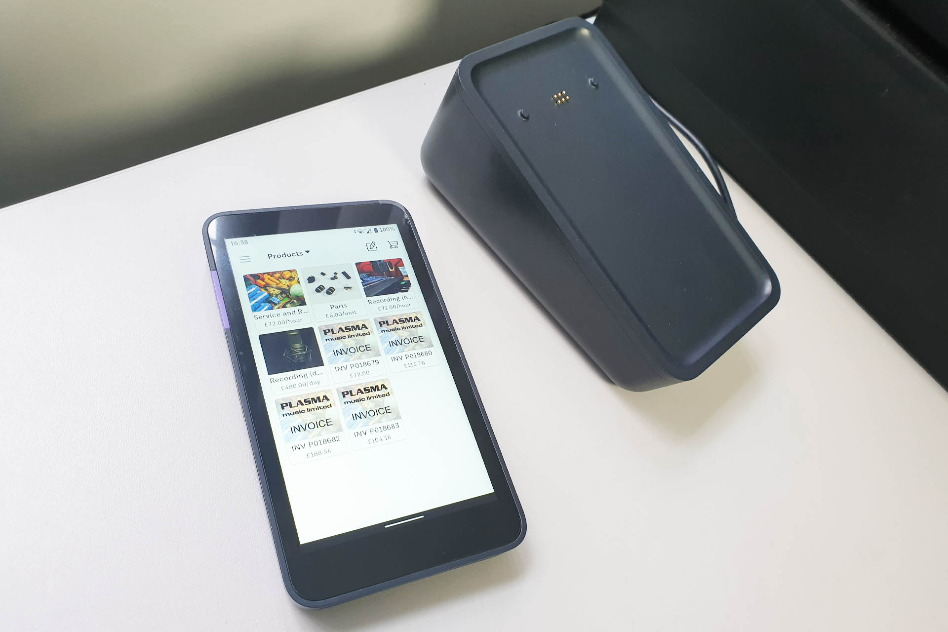
It's been a while but I now have Point of Sale facilities at Plasma Music.
Things have moved on since Plasma Music was based on the local industrial estate and although great at the time, by today's standards, my old PayPal Here just doesn't cut it.
The vast majority of my customers pay on-line but my new Zettle account and hardware will hopefully make things a little easier for those who just decide to drop in.
Every once in a while, I receive an e-mail from a very happy customer and it just makes my day. For anyone doing the kind of work that I do, a little appreciation is always welcome. On this occasion, I've decided to post James' e-mail and the picture he included.
James' Roland MKS-70 back home in its rack after all major upgrades were installed and the unit was repaired.
James sent me his Roland MKS-70, a few months back and wanted all the MKS-70 upgrades installed. It wasn't until the unit was in transit from sunny Washington state, USA that he told me there was an issue with the unit.
James also asked if I could change the battery in the M-64C memory cartridge that he included with the unit. In fact, I used this M-64C as a test sample for my M-64C labels. 🙂
Anyway, here's the e-mail that I received from James:
"Hi Alex,
Just wanted to thank you for all your hard work and not giving up when problems arose! What you sent back is just simply incredible! Thanks for the extra patches as well!
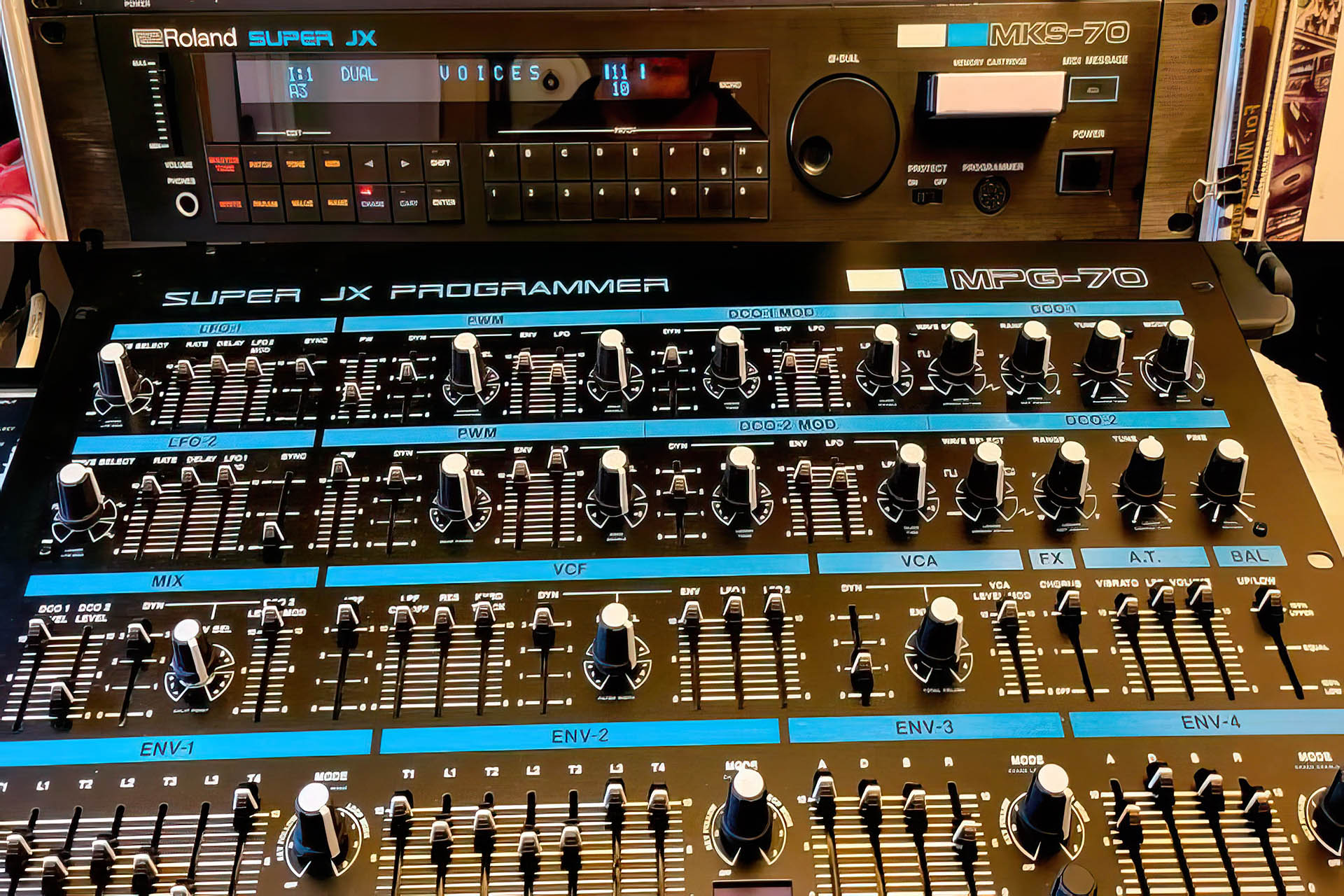
I also bought the MPG-70 programmer you talked about to even make my unit that more awesome! It's nice to know there are such good people in this world.
James"
James even put a comment on Google Reviews, my very first Google review!!!! As I said, a little appreciation is always welcome. 🙂
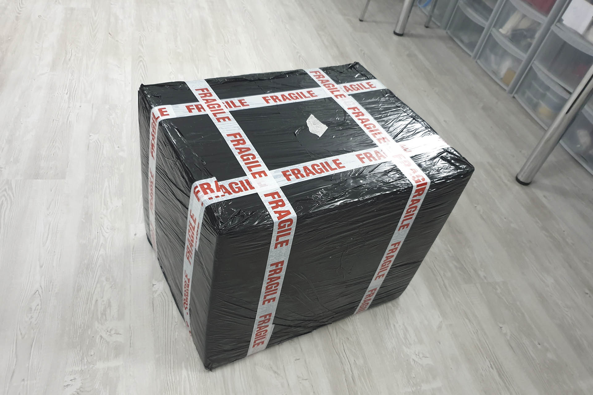
I don't like taking chances and so James followed my packaging instructions implicitly. In fact his packaging was so substantial, I was fully confident to reuse it to return his beloved synth module.
James' MKS-70 all ready for the long journey home.
Sending your favourite synth module half way around the planet is a daunting prospect but I actually receive a lot of gear from the USA, Canada and even Australia and Japan. If you feel inclined to send me your gear, please begin by liaising with me via e-mail. This can be initiated here. I'll recommend proper packaging, etc and my DHL account allows me to arrange collection, if it's easier for you.
I've been meaning to do this for several years now but tonight I finally got my CAA Flyer ID.
Over the past couple of weeks, I've been making a little time to sort out all the requirements so that I can 'drone legally'. After getting a CAA Operator ID for Plasma Music Limited, I then had to sort out a Flyer ID for myself. This involved an on-line test. Then of course there's insurance, blah, blah, blah.
My first 'legal' drone snap. Taking off over trees at the back of my house in Grovehill, Hemel Hempstead. I think I'm going to enjoy this!
Anyway, I'm delighted to announce that everything is sorted and I can now expand my photographic and video services to the sky! 🙂
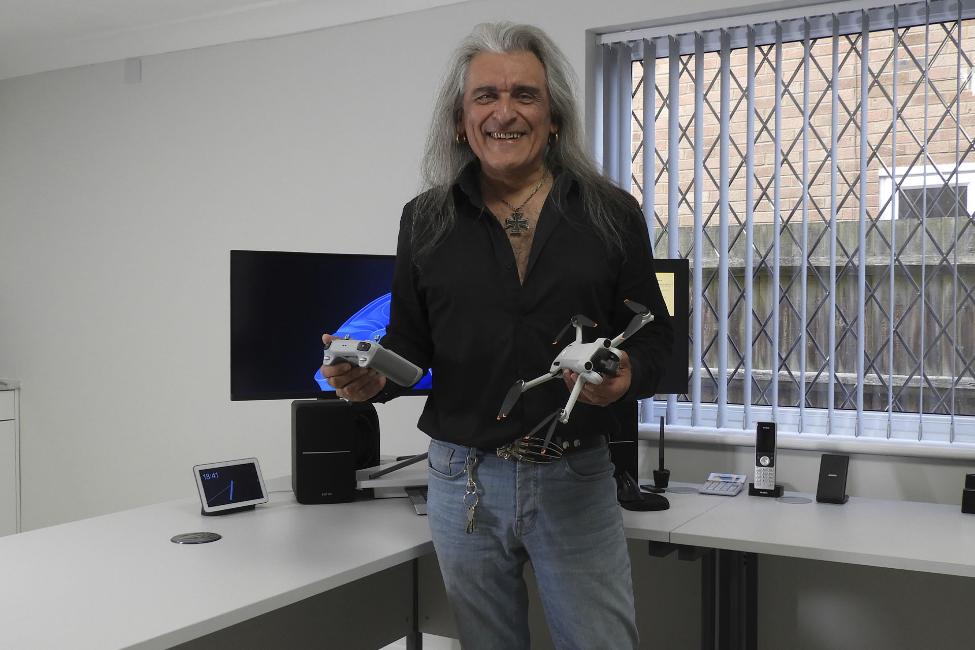
I'm so lucky to have met some lovely people over the years and got to know many customers on a personal level. One of them is Alex Simler. Alex is... well, kind of a bit geeky, eccentric, loves old gear and recently commissioned me to build a power supply for the Elektron MachineDrum Mk1.
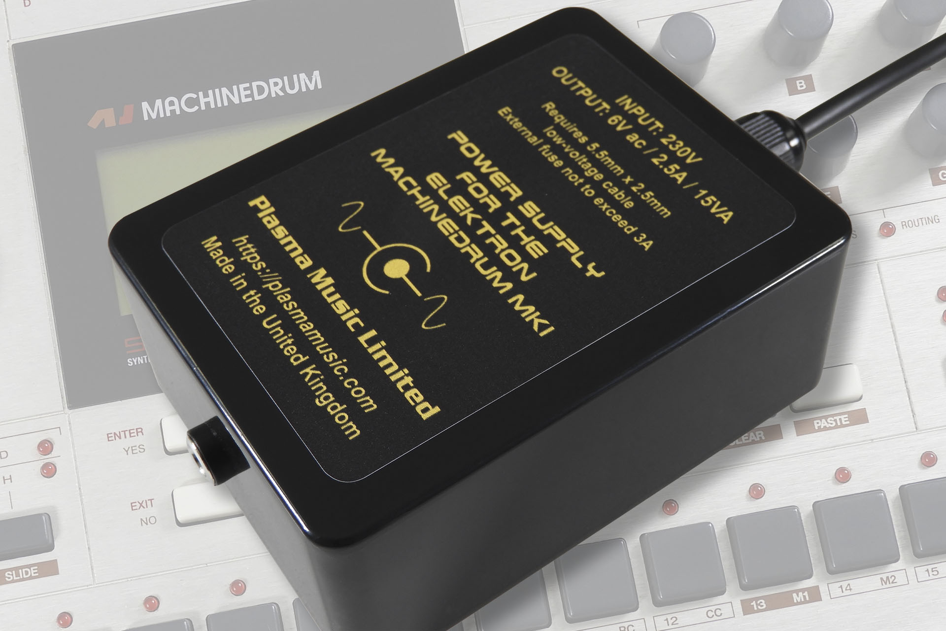
Being a simple 6V ac supply, this wasn't a particularly challenging or even difficult project. Alex lent me his MachineDrum Mk1 as he was off to New Zealand for a couple of weeks and this would be an opportunity for me to knock something together. After a couple of days and in-between my regular stuff, I WhatsApped Alex a picture of the finished product.
A detachable low-voltage cable, helps provide added reliability.
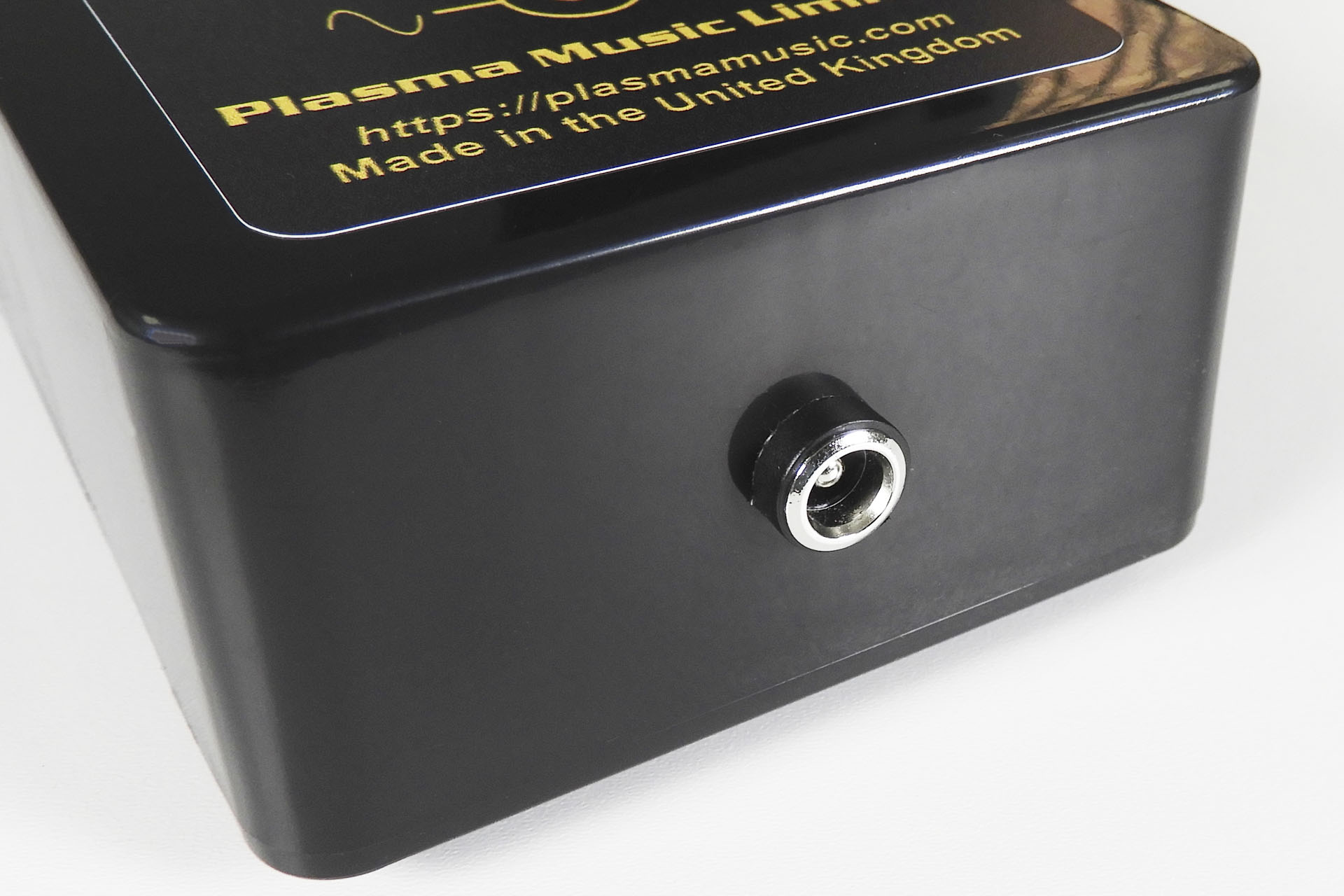
Yeah, okay, it's a bit more fancy than your average wall-wart but that's just me. While the power cable is integral, the low-voltage cable is detachable. Hey let's face it, these cables get mashed, right? Having a detachable cable means that when your cable does get müllered, you can just buy another one or even just have some spares. It's a standard 5.5mm x 2.5mm DC cable and available for a couple of quid, bucks, Euros or whatever from Amazon.
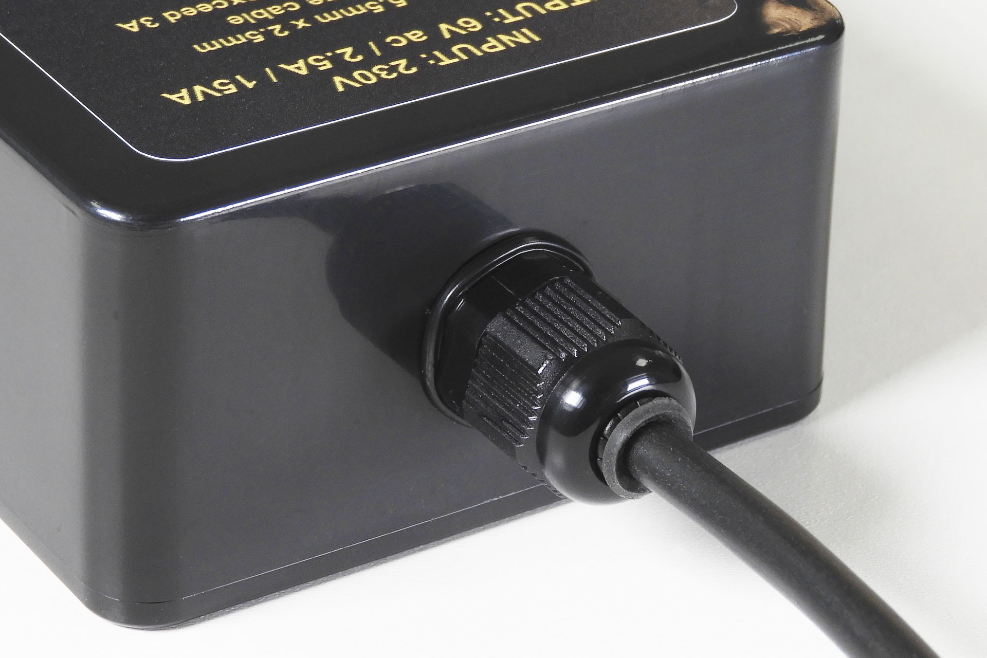
An extra tough cable gland ensures that the power side of the power supply, is very secure.
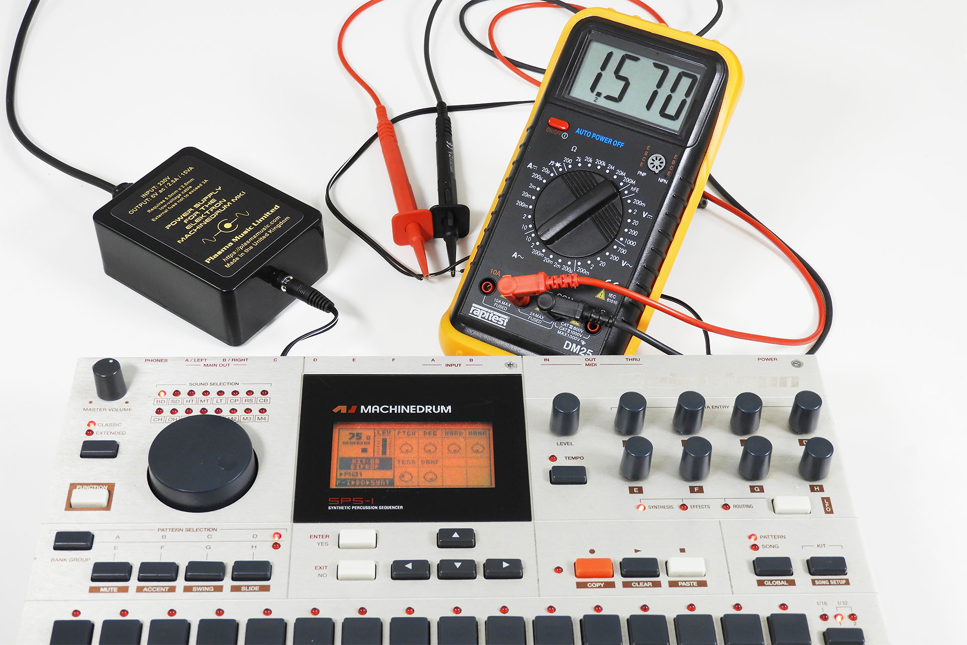
The MachineDrum Mk1 pulls about 1.6A from a 6V a.c. supply. This means that the current supplied from the mains into the primary of the transformer is about 42mA when used on a 230V supply. Here's how you work that out:
Supply Voltage = 230V Secondary Voltage = 6V Voltage Ratio = 6/230 = 0.026 Secondary Current = 1.6A Primary Current = (Voltage Ratio \times Secondary Current)A Primary Current = 0.026 \times 1.6A = 0.042A
So with a current consumption of 42mA from a 230V supply, a standard value 63mA slo-blo fuse should be fine. WRONG! You need to cater for transients on the mains supply and I would normally double this without compromising safety. Hence the internal fuse is rated at 120mA.
Since power is the product of voltage and current, if the supply voltage is halved from 230V to 115V, you have to doublethe current to maintain the same power. Hence the fuse rating on a 115V supply, is 250mA (kind of 2 x 120mA). Hope that all makes sense.
At 15VA, my power supply for the Elektron MachineDrum Mk1 is overrated. In fact, it can supply about 56% more current than what's required by the MachineDrum so it won't get hot! 😎
Despite its simplicity, my PSU-MDMK1 was fully tested. As you can see, the MachineDrum Mk1 requires about 1.6A and I'm pleased to report that my power supply only gets slightly warm when in use. YAY!
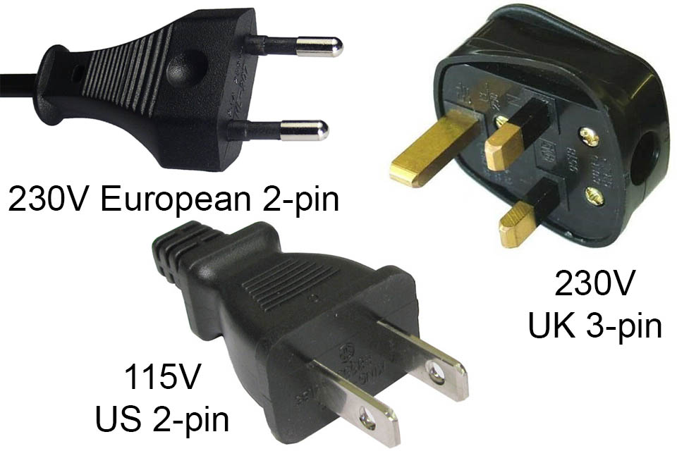
This power supply for the Elektron MachineDrum Mk1 is offered with either
a 3-pin UK plug with the PSU configured to operate on 230V.
a 2-pin European plug with the PSU configured to operate on 230V.
a 2-pin US plug with the PSU configured to operate on 115V.
PSU-MDMK1 can be supplied with one of these three common power plugs.
Anyway, the main thing was that Alex returned from his New Zealand adventures and loved his new power supply!
Incidentally, this power supply for the Elektron MachineDrum Mk1 which I've christened 'PSU-MDMK1' (well I had to call it something), can also be used on the Elektron MonoMachine Mk1.
Supplied with a 1m low-voltage cable with 5.5mm x 2.5mm barrel type connectors on each end to go straight to your MachineDrum Mk1, PSU-MDMK1 is available to purchase here...
If you need help with any Elektron products, the Elektronauts forum is a great resource. Please do check it out.
And finally...
THIS POWER SUPPLY IS NOT COMPATIBLE WITH THE
ELEKTRON MACHINEDRUM MK2
UPDATE - 3rd December 2022
While I thought I was quite thorough with the information that I provided about my replacement power supply for the Elektron Machine Drum Mk1, I regularly get people asking me if it hums!
At first I didn't know why people were asking about hum but after working out that many desperate MachineDrum users had been forced to buy cheap 6VAC power supplies that use conventional 'framed' transformers, it all made sense.
So to reassure and make things clear, my PSU-MDMK1 does NOT hum.
The reason I say that so confidently is because my power supply uses a more expensive, high-impedance toroidal transformer. The absence of laminates held together in a resin (the composition of which is probably unknown), means that there is nothing to oscillate to the frequency of the mains.
UPDATE - 18th January 2023
I recently got a MachineDrum Mk1 in that had been damaged in the post. The display cover was cracked and the display itself was intermittently failing to come on. Read how I installed a replacement display here.
Now doesn't that look cool!
UPDATE - 20th January 2024
Displays arrived this morning so two machines will be going back to happy customers (one in Germany) soon! 🙂
New PSU-MDMK1 power supply for MachineDrum Mk1 and new displays for MachineDrum Mk1 and MonoMachine Mk1.