My NC-7 noise cancelling mod for the Simmons SDS7 is for those SDS7s that didn't get this mod factory fitted.
"Surely that can't be" I hear you ask.
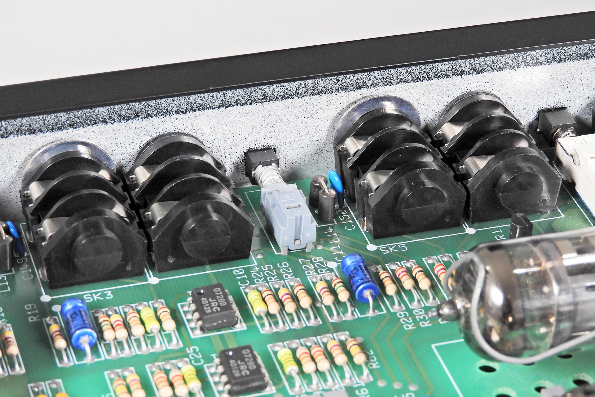
Pictured below, is part of the Simmons SDS7 showing the quad op-amp, part of which is used to buffer the stereo outputs. Due to the mish-mosh of analogue, digital and power tracks on the back plane, Simmons was forced to come up with an easy retrofit solution to reduce specifically, CPU noise picked up by the stereo buss. Able to take advantage of a spare op-amp stage in the TL084 and dropping an 'aerial' on the rear of the back plane, inverted noise was mixed on to the stereo buss, thereby cancelling out the 'in-phase' noise. Highlighted in red is the pre-set pot and the two 10kΩ resistors which were part of that mod.
There are however, a few SDS7s out there that didn't get the mod! Pictured below, is my test SDS7 which I used to develop Pleiades, Dark Matter and AMEP and as you can see, it didn't get the mod fitted back in the day.
You'll also notice the absence of a small green capacitor, highlighted in yellow on the second image. This 47pF capacitor which is connected between pins 10 and 12 of the TL084, is sometimes soldered on the back of the back plane PCB. More about this later.
Well, I was going to implement the mod as per the original service bulletin but as it turned out, the track layout of the back plane version in my test SDS7 was different to later revisions and I wasn't able to drill the three holes for the pre-set without busting a track.
Then I had a thought; "Why don't I knock up a little snap-in PCB to do the job?" That way, anyone with a SDS7 that didn't have the noise cancelling mod installed, could also benefit. 🙂
Snaping into the IC socket that the TL084 is in and taping the aerial on to the rear of the back plane, means that NC-7 can easily be installed in a few minutes.
Of course it's not quite that straight-forward. The noise cancelling circuit has to be 'tuned', hence the pre-set pot. Instructions on how to do that are in the installation manual and that process also takes only a few minutes.
The two through-hole resistors of the original mod, are replaced by SMD 0805 resistors that are situated underneath the IC on NC-7. That 47pF capacitor I mentioned earlier, is also superfluous as on the underside of the NC-7 PCB is a SMD 2010 47pF capacitor. Hence, if the original capacitor is indeed soldered to the rear of the TL084, it must be removed.
Irrespective of where the 47pF is located, it should be removed as NC-7 has a 47pF on-board.
NC-7's aerial wire can't simply flip over the back plane PCB. That's because one of three guides guide in the SDS7 top-case secures the back plane PCB exactly where the aerial wire needs to be. The wire I chose for the NC-7 aerial wire is CAT5/6 cable strand so it's solid. If it catches into the guide of the top-case, it'll break. Hence, the aerial wire has to go to one side.
In a similar manner as the original mod, the aerial from NC-7 is hot-glued to the rear of the back plane in between the edge connectors for modules 9 and 10 and across the stereo outputs busses.
So while looking into the infamous SDS7 noise and testing my NC-7 noise cancelling mod for the Simmons SDS7, I thought it might be an idea to actually record this annoying phenomenon.
The video below shows the effect on overall noise level, as the NC-7 noise cancelling mod is gradually tuned in. Check out the VU meter on the right.
WARNING!!!! The signals have been amplified so TURN DOWN YOUR SPEAKERS
Below is a spectral capture of the noise and the effect of the NC-7 noise canceller. As can be seen, tuning in the NC-7 noise cancelling mod, reduces noise between 3kHz and about 11kHz but doesn't do anything for lower frequency noise.
There's one other thing... In fact, you may already have noticed, that instead of using a TL084, NC-7 is fitted with a newer NJM2060. This device is of a much higher specification than the humble TL084. Since two stages of this quad op-amp are used to buffer the stereo buss, having a quieter device will no doubt improve things a little. 🙂 Having said that, I'm not sure the difference will be too noticeable with all of that other stuff!
NC-7 is handmade in Hemel Hempstead, Hertfordshire, United Kingdom, only a few miles from St. Albans where Simmons used to based and where I used to work.
I do not keep NC-7 units in stock and each NC-7 is built to order.
Pictured is NOT a hacked original SDSV blanking plate but a newly developed aluminium plate which is the basis of SDSM. Hey, just in case you're wondering.
SDSM - MIDI for the Simmons SDSV does what it says on the packet. With the addition of a Tubbutec uniPulse MIDI to trigger converter, SDSM makes it really easy to add MIDI triggering to the Simmons SDSV WITHOUT drilling holes or making any other permanent modifications to your vintage synthesiser drum system.
When looking to buy my first Simmons SDSV several months ago, I immediately considered adding some type of MIDI triggering. The problem was that MIDI to trigger interfaces are quite thin on the ground, probably because it's such a limited market. Something like the Simmons MTM was a bit over the top for my needs so imagine my delight when I stumbled across uniPulse by Tubbutec.
Yes, of course I considered designing my own MIDI to trigger converter but after buying a uniPulse to basically try out, I knew I'd found what I was looking for so why would I reinvent the wheel, guys? From my trial tests, tubbutec has done an excellent job and they come across as really nice guys, too.
At the heart of the uniPulse kit is a small PCB but also supplied, are various accessories, allowing for easy integration into many different electronic drum systems and even vintage, pre-MIDI drum machines. When buying your uniPulse for your SDSM, just ask Tobias for a SDSM pack for the Simmons SDSV and he'll send you exactly what need.
Measuring a mere 43mm x 40mm, uniPulse is beautifully compact.
SDSM comprises two fundamental parts; the faceplate and an internal bracket to hold the small 40mm x 43mm uniPulse PCB.
uniPulse conveniently mounts to the bracket that's on the back of the SDSM faceplate.
The faceplates were modelled on the original blank SDSV faceplates so they look quite at home on the SDSV. Having said that, it took a couple of tries to get everything to line up (metric, imperial, metric, imperial, GRRRR). When designing printed circuit boards, I always print on to paper first, when I can. It's quite different in this case however, to have a piece of aluminium in your hands and on your SDSV.
As you can see I even changed things slightly, between my second and third prototypes.
It took three attempts to get things right, two of which are shown above, together with a SDSV blanking plate. The first? Well, I couldn't have got the dimensions more wrong! Above, you can just make out the mill finish under the paint on the final prototype. It looks a lot more authentic in real life.
You may have worked out by now, that the installation of SDSM requires one prerequisite; that your SDSV has a spare module slot. 🙁 Yeah, sorry about that.
There are two types SDSM; SDSM and SDSM HH. The former is for any SDSV but the latter is specifically for those users who have an original Simmons SDSV hi-hat pedal. SDSM HH has an additional toggle switch to allow the hi-hat open / closed control function, to be taken from either an original Simmons hi-hat pedal, or MIDI.
If you have a SDSV with a hi-hat module but you don't have an original Simmons hi-hat pedal or have no desire to use the hi-hat open / closed function via a pedal input, then you should choose the standard SDSM module as the chances of picking up an original Simmons hi-hat pedal are going to be pretty remote.
Available as SDSM and SDSM HH, the latter is specifically for those who are lucky enough to have an original Simmons hi-hat pedal and who would like to continue using it. The additional switch allows you to select between hi-hat open / closed control via MIDI or pedal.
As stated in the opening paragraph of this post and in keeping with all my upgrades and modifications, SDSM - MIDI for the Simmons SDSV, can be easily removed, thereby returning your SDSV to factory. You don't have to drill any holes or do any type of permanent modification to your SDSV, to get SDSM to work.
MIDI into the SDSV is via the unused pad trigger input so no holes need to be drilled into your SDSV.
MIDI IN is via the unused module pad trigger input and SDSM includes a male XLR to female 5-pin DIN so all you need to do is hook up a standard MIDI connection from your studio and you're off! 🙂 Coolamundo, dude!
No hole to be drilled for a MIDI socket. Just use the redundant module pad trigger input.
SDSM mounts the uniPulse MIDI activity LED on the front panel which makes things very accessible. In fact, you have a choice of red LED, in keeping with the rest of the SDSV front panel, or a green LED, which is the same colour as the MIDI activity indicator on a lot of other gear in my studio, specifically Roland.
SDSM is available with a choice of red LED to match your SDSV or green LED which is more standard amongst MIDI activity indicators.
I'm saying this a lot but... as with all my upgrades and modifications, SDSM is accompanied by a highly illustrated and detailed installation manual.
Below is my own Simmons SDSV. SDSM looks like it's always been there. Love it! 🙂
A WORD OF THANKS
In recent years, I've observed how people are tending to try to do stuff completely by themselves. Hey there's a video on YouTube, right?!?!? 🙁 In fact, the increasing lack of collaboration I see, deeply saddens me. The development of SDSM however, is a great example of just how things could and perhaps should work.
I'm a bit old school and since the SDSM faceplates were modelled on the original SDSV blanking plates, I felt obliged to give a call to my friend, Dave Simmons to ask his permission to use his logo.
I also contacted Tubbutec as it was my intention to have the Tubbutec logo on my new SDSM faceplates, too.
Well, Dave got back to me pretty quickly and he was delighted with all the work I'm doing, to keep vintage gear alive and hopefully going for a few more decades.
As it turned out, Tobias from Tubbutec and I really hit it off. In fact, following a couple of e-mail exchanges, he even modified the uniPulse firmware. What a star!!!! 🙂
During the development of SDSM, there's another gentleman who lent me a very big helping hand. Ed Rose, akaThe Simmons Guy, has installed considerably more uniPulses than I have and Ed has extensive knowledge pertaining to the 'quirks' of the SDSV when adding MIDI triggering. Ed was also in on the suggestions for the 'Simmons' firmware upgrade for uniPulse.
So to conclude my acknowledgments, I have to say that I feel quite privileged to be in a position to thank Dave Simmons, Tobias of Tubbutec and Ed Rose but it all means just a little bit more because they helped me with one of my little upgrade projects.
You can buy SDSM here but please note that for the time being, you'll have to purchase a Tubbutec uniPulse yourself, directly from tubbutec.de
SDSM is made locally here in the United Kingdom. In fact, it's made a few miles away from where I used to work a million years ago, at the old Simmons factory in St. Albans, Hertfordshire. All materials, machining, mill finishing, painting and silk screening are supplied by local companies. It's something I'm quite passionate about and positively insist on. 🙂
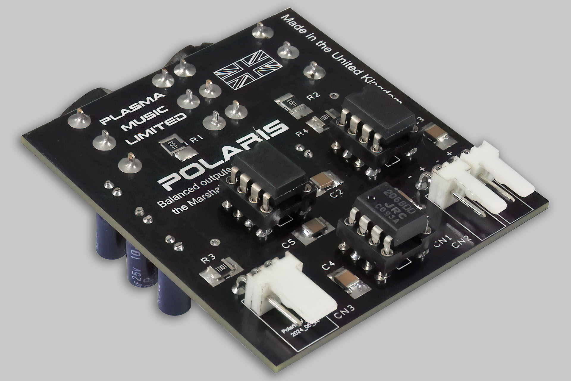
Polaris balanced outputs for the Marshall JMP-1 gives our favourite MIDI valve pre-amp something that it should have had thirty-two years ago!
So why didn't Marshall do this in the first place? Well, perhaps for the same reason that many manufacturers at the time, didn't put balanced outputs on their gear. Yeah, I'm none the wiser either!
Anyone with professional music performance or recording experience, will be aware that balanced audio connections aren't just used extensively in any big live set-up or recording studio but are pretty standard in those environments. In my own studio, EVERYTHING is balanced.
Balanced signals provide increased immunity to external noise, deliver a signal that's +6dB hotter than the unbalanced equivalent and are low-impedance so can run long distances.
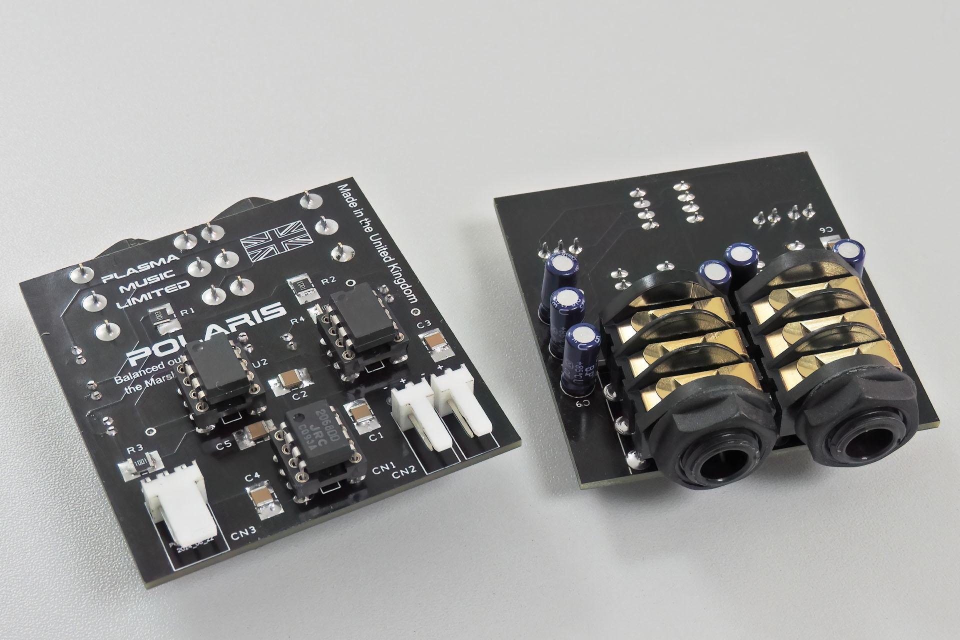
Component density looks low but some components, like the bi-polar electrolytics are on the underside of the PCB.
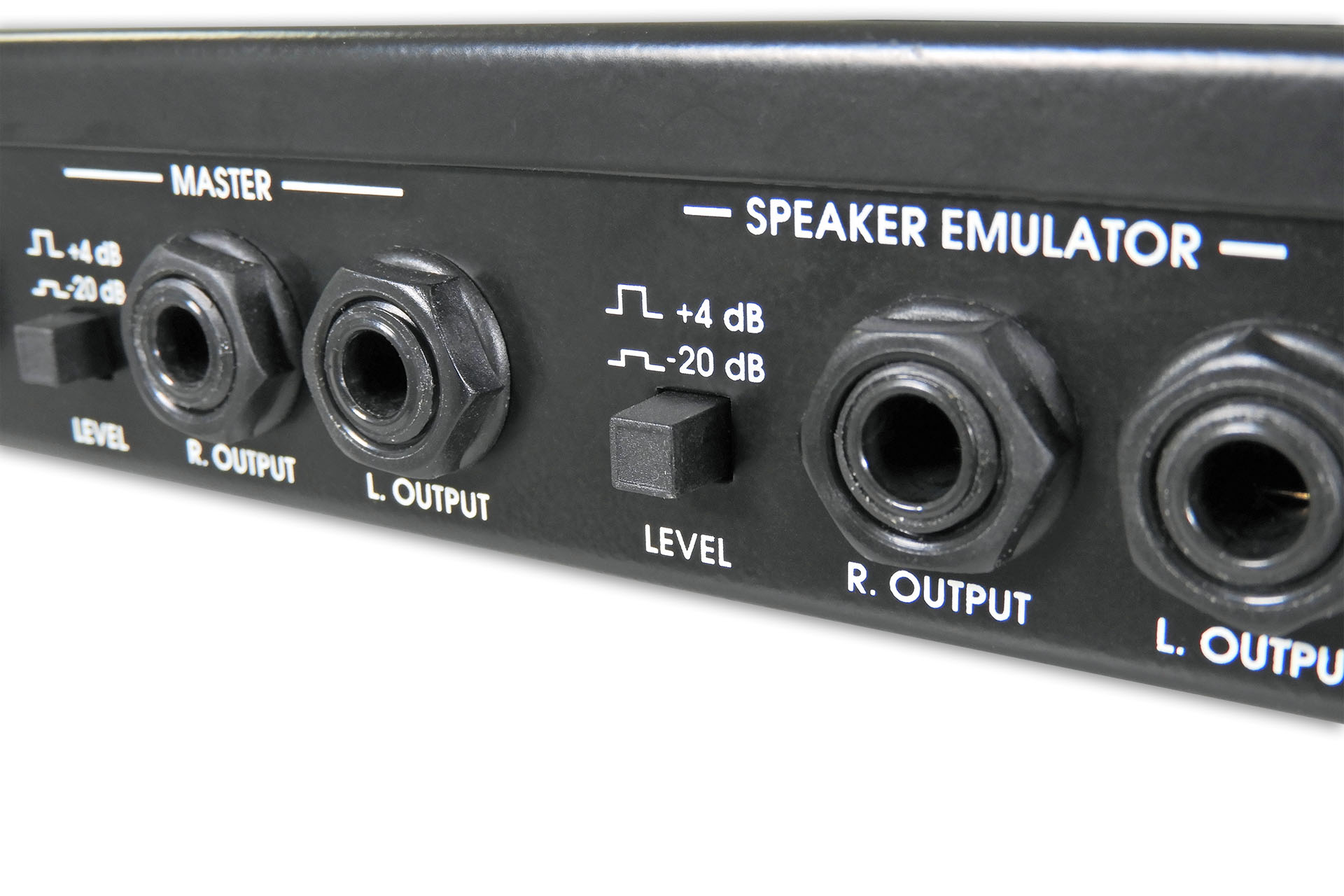
The Marshall JMP-1's outputs already have the option to switch to +4dB so to have them balanced makes sense.
SO WHAT DOES BALANCED ACTUALLY MEAN?
Firstly, unlike a normal (unbalanced) connection which comprises a single signal conductor and a return conductor (usually a screen), a balanced connection has three wires; an in-phase signal carrying conductor, an out-of-phase signal carrying conductor and of course, a screen.
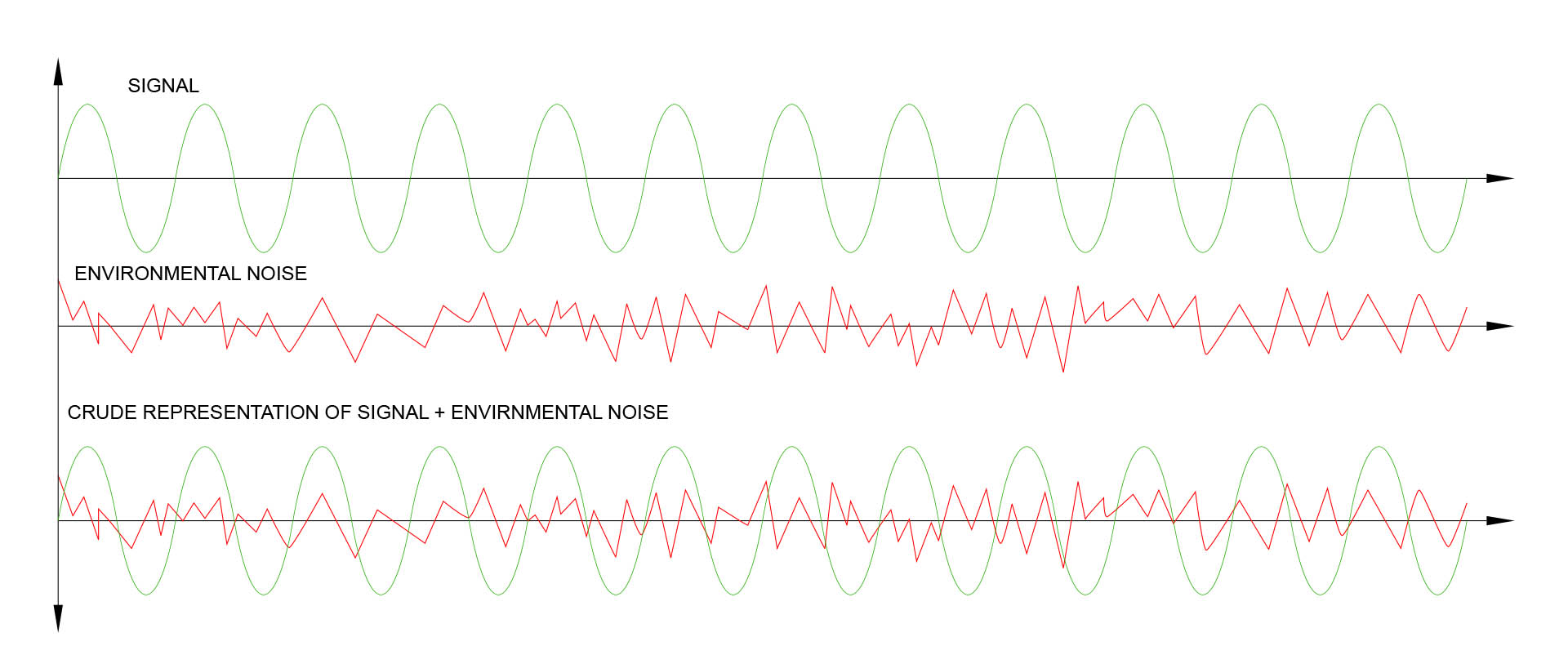
Looking at a normal audio connection, any noise can be picked up by the single signal conductor, even through the screen. This will be passed on to the input of the destination device, like a mixer, for example.
Crude representation of a simple sine wave over an unbalanced line, mixed with noise.
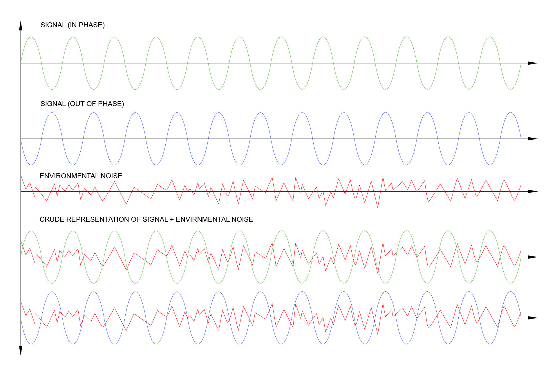
On the other hand, any noise picked up by the two signal conducting lines in a balanced system, will appear equally in amplitude and phase on both lines. When fed into a differential amplifier (balanced input) all signals common to both lines, are removed and the only signal that's common to both lines is noise that's been picked up between the outputs of our sending device and the inputs of the receiving device. That's fundamentally, how balanced lines works.
Notice how noise is the same as it affects both in-phase and out-of-phase signals in a balanced line system.
There is a third advantage to using balanced lines; balanced systems are low-impedance and without going into even more physics, they're able to drive signals over much longer distances than high-impedance systems.
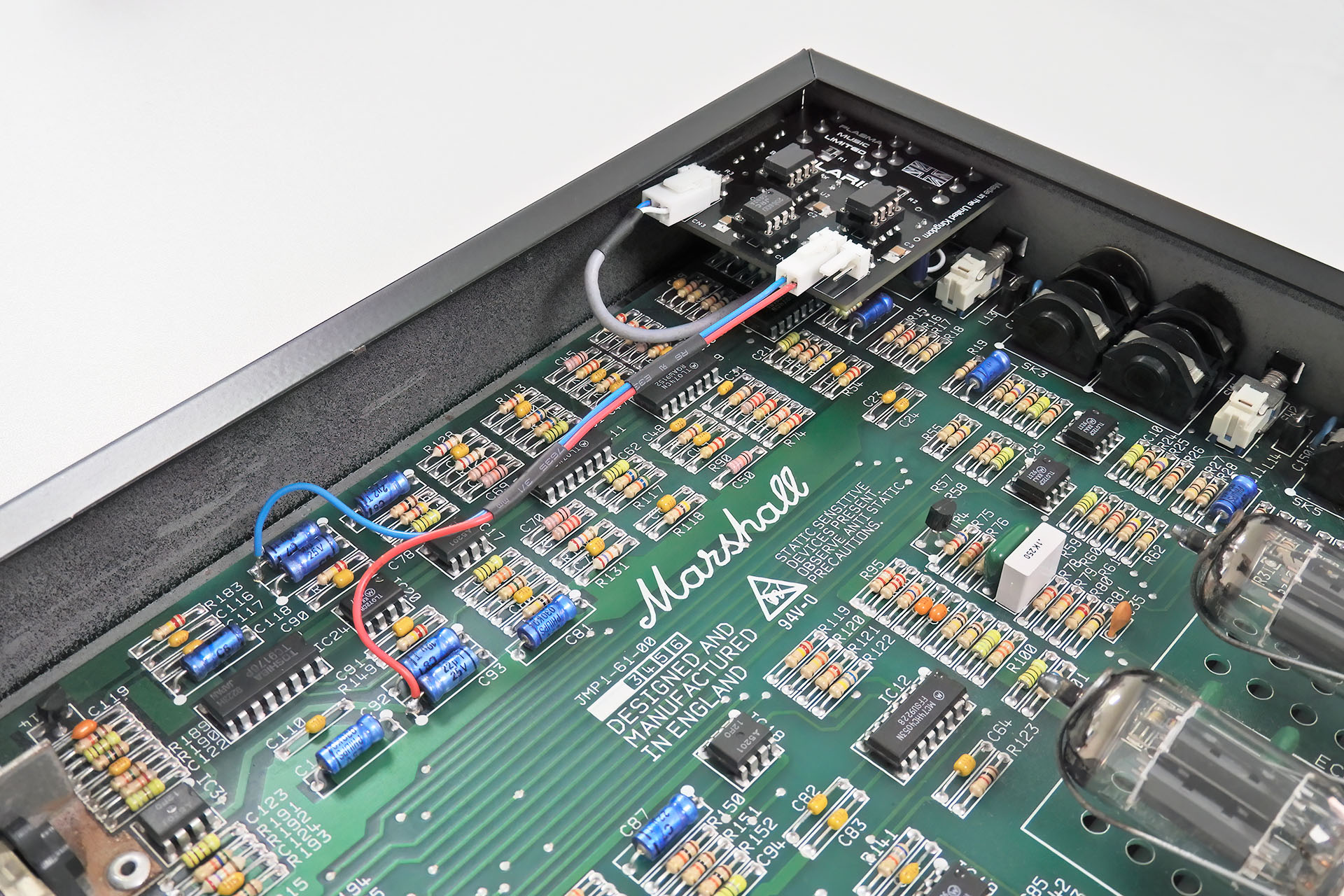
Polaris balanced outputs for the Marshall JMP-1, uses the same principles and components as my Nebula balanced outputs jack-board for the Roland MKS-70. A no-compromise design, Polaris has precision high impedance buffers on its inputs and dedicated balanced line drivers on its outputs, thereby guaranteeing the cleanest and most phase-coherent signal possible. With lots of attention to detail, the design includes for example, excellent separation between the audio tracks and the +/-15V rails. The feeds to Polaris from the JMP-1 main-board are via screened cables, thus ensuring minimal pick-up of noise from within the JMP-1. Polaris even uses gold-plated jack sockets!
All ICs have decoupling on both supply lines and all inter-op-amp connections are via high-quality unpolarised electrolytic capacitors, thus ensuring that no unwanted DC gets to the outputs. The signal path is minimalistic and very tidy indeed!
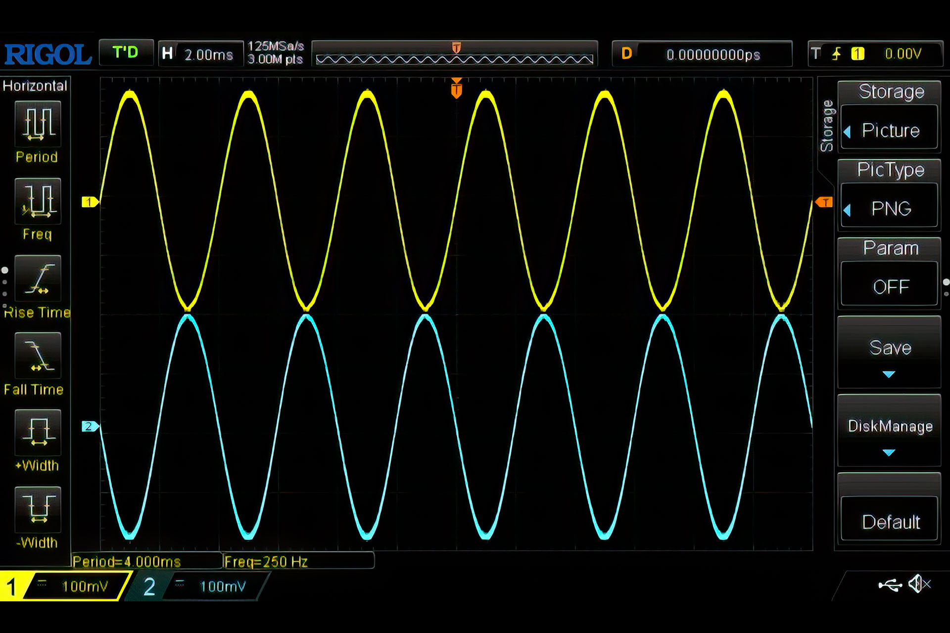
Here's a screen capture of my first test of Polaris. As you can see, with dedicated differential line driver stages, the phases are perfectly opposing.
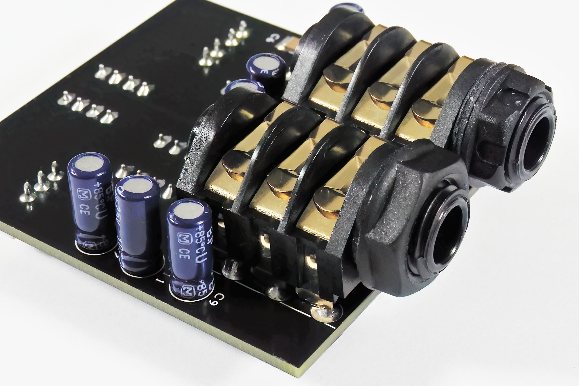
When designing Polaris, the biggest challenge was how it would physically integrate into the JMP-1, especially in such a way that anyone with a good level of competence, can install it.
Of course the original two-pole sockets have to removed and (of course) you can't just connect three-pole (balanced) sockets in their place. My solution was to make a small, light-weight PCB that would mount using the rear sockets. Further connections to power and audio are made via Molex headers.
Polaris tucks in nicely into the Marshall JMP-1 with power taken from conveniently available +/-15V points.
Marshall should have at least made the speaker emulated outputs balanced as they will inevitably be used for recording or sound reinforcement. Indeed Polaris was originally supposed to replace just those outputs.
Polaris however, soon evolved as I considered the master outputs and here's why...
Quite simply, more and more users are choosing to record from the JMP-1's master outputs. Feeding them into any one of a million impulse response speaker / cabinet simulation plug-ins, provides artists with considerably more options and in many a view, considerably better results than recording from the original speaker emulated outputs.
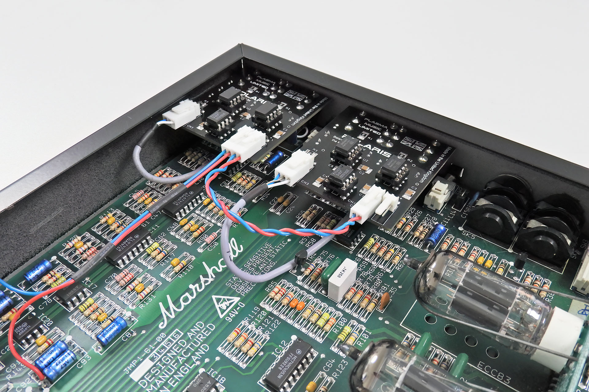
A versatile solution, Polaris gives you the option to have either one pair of outputs or both emulated outputs and master outputs, balanced. In fact, you can just do one pair now and fit another Polaris whenever you want.
Convert one or both pairs of outputs to balanced. Do one at a time or both simultaneously.
In a dual Polaris set-up, you only need to connect one of the boards to +/-15V on the JMP-1 PCB. A simple 'POWER LINK' connection between the two Polaris boards, delivers power from one module to the other. Coolamundo, dude!!!!
Polaris incorporates PowerLink for easy power connection between two Polaris modules, giving peace of mind if you wish to upgrade at a later date.
PLEASE BE AWARE
The Marshall JMP-1 already runs natively at +4dBm, about 1¼ Volts. Polaris makes the JMP-1 fully, professionally compliant by giving it balanced outputs. There is however, a caveat.
Switches on the rear, offer level attenuation down to -10dBm, about ¼ Volts allowing the JMP-1 to be connected to consumer electronics. When the level switches are set to -10dBm however, the output impedances of the JMP-1 change. This change is NOT compatible with Polaris as it adversely affects the frequency response of the stage.
I feel obliged to point this out but on the other hand, if you’re wanting balanced outputs, then why would you want them running at consumer level?
Of course, the position of the level switch for the effects loop is quite independent of the master and speaker emulated outputs and so, works as it did before.
HEY, AND DON'T FORGET... With Polaris installed, you can still connect your JMP-1 to unbalanced inputs. Of course you won't get the benefits of a balanced line connection but things will still work just fine. Over thirty years since its launch, the Marshall JMP-1 seems to be as popular as ever. Polaris balanced outputs for the Marshall JMP-1 ensures that using our favourite MIDI valve pre-amp with a sound reinforcement system or in a recording environment, will yield the best possible results with improved immunity to noise and hotter signals.
Polaris costs the same as a professional studio grade D.I. box. Being active however, means that it doesn't 'colour' the sound and has excellent phase-coherency over the entire audio spectrum. Of course, being integrated into your Marshall JMP-1 also means that there's one less box to carry around. 🙂
Polaris is handmade in Hemel Hempstead, Hertfordshire, United Kingdom, only a few miles from Bletchley, Milton Keynes where the Marshall Factory is and where the JMP-1 used to be made.
I do not keep Polaris units in stock and each Polaris is built to order.
Check out all of my other JMP-1 stuff here. or you can buy Polaris here:
A FEW POINTS TO NOTE...
I design a lot of upgrades / mods for various pieces of vintage music technology but... I really don't like hacking stuff.
What I mean, is that there's no way I would consider designing things that would require holes to be drilled or any other mutilations to be performed on our beautiful vintage gear. Indeed, all my upgrades and modifications are fully reversible. They can be quickly and easily removed allowing equipment to be returned to its original factory condition. Whilst sometimes a design challenge, for me, this is a big deal as I really value this old tech'.
And lastly... Occasionally, I get asked to design mods that will change the sound. Well, I'm afraid I don't do that. My feeling on the matter is quite clear; if you don't like the sound of something, get something you do like the sound of! What's the big deal, guys?
A few weeks ago, I decided to test an old theory of mine; a simple cable change for a Simmons SPM8:2 noise reduction mod.
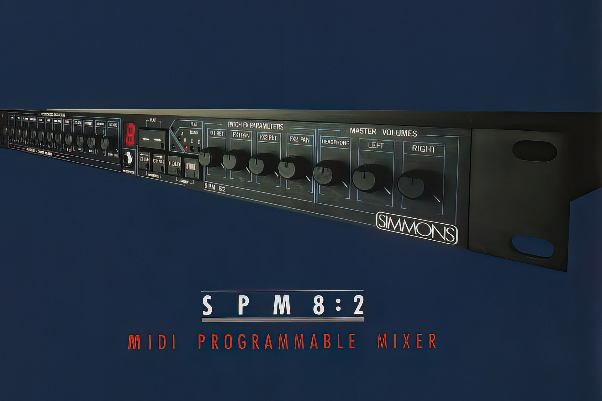
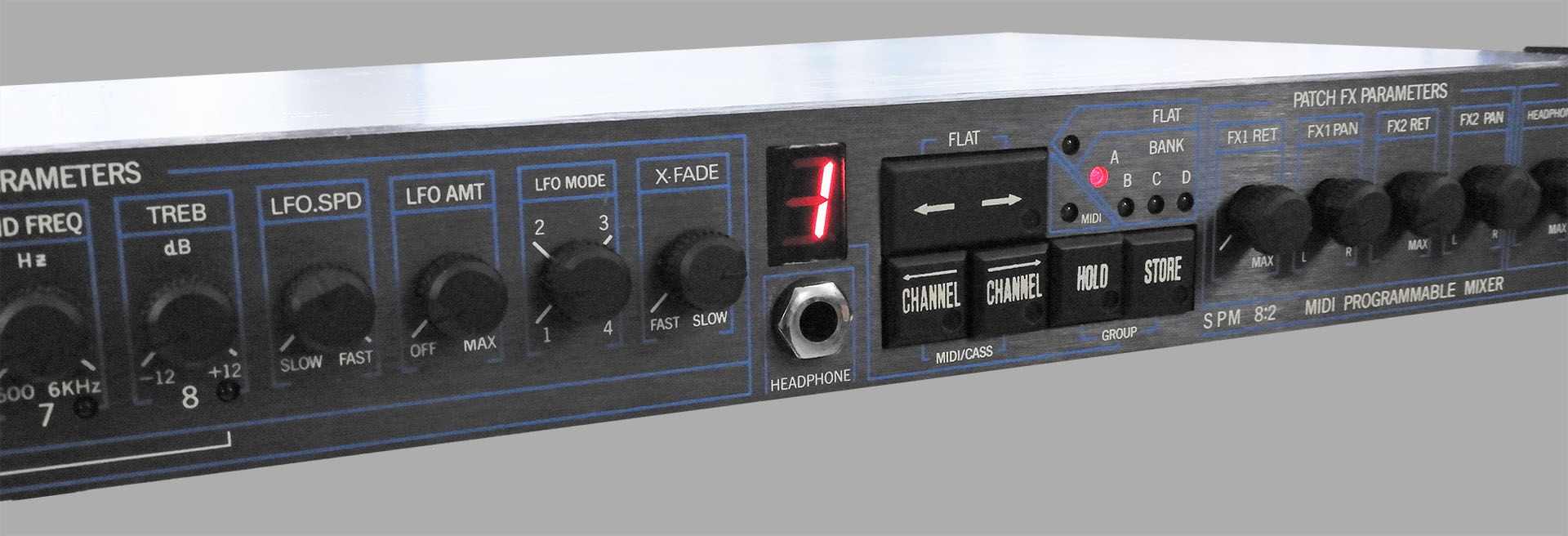
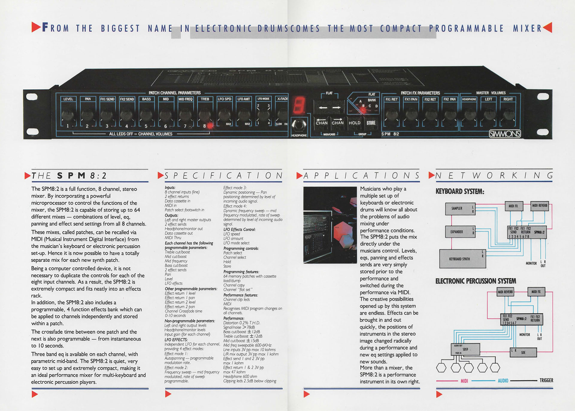
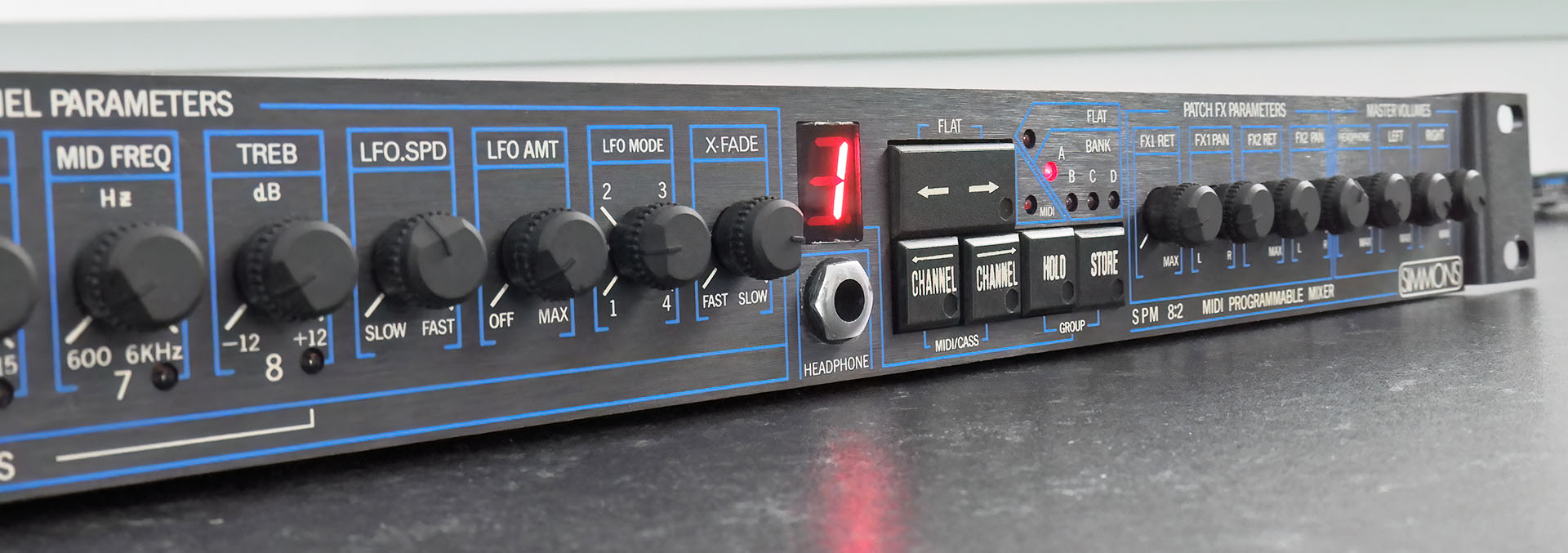
Back in 1987, one of the revolutionary products that Simmons released was the SPM8:2 digitally controlled analogue mixer.
The world simply hadn't seen anything like this before. Suddenly, keyboard players, e-drummers and even studio engineers, could knock up a mix of eight signals, with effects, store that mix in a patch and recall several patches during a single performance or recording session.
Crammed into 1U, things were tight and indeed apart from heat, the SPM8:2, was criticised for its poor noise levels. There was and still is, talk about replacing the TL084s with more modern devices like the OP471. Geesh, people even said that TL072s would deliver an improvement. The use of transconductance amplifiers (OTAs) to control analogue signals helped a lot. Being current-based, there was very little cross-talk from control voltages to audio, inside the control ICs.
The truth however, is that the noise results from the close proximity of the digital electronics to the analogue electronics. The fact that the characteristic of the noise is not your classic and constant shhhhhhh but a type of chatter, confirms that. Shorting all inputs and muting all channels doesn't alter things too much so again, it seems that noise is being generated internally.
Okay, so let's have look...
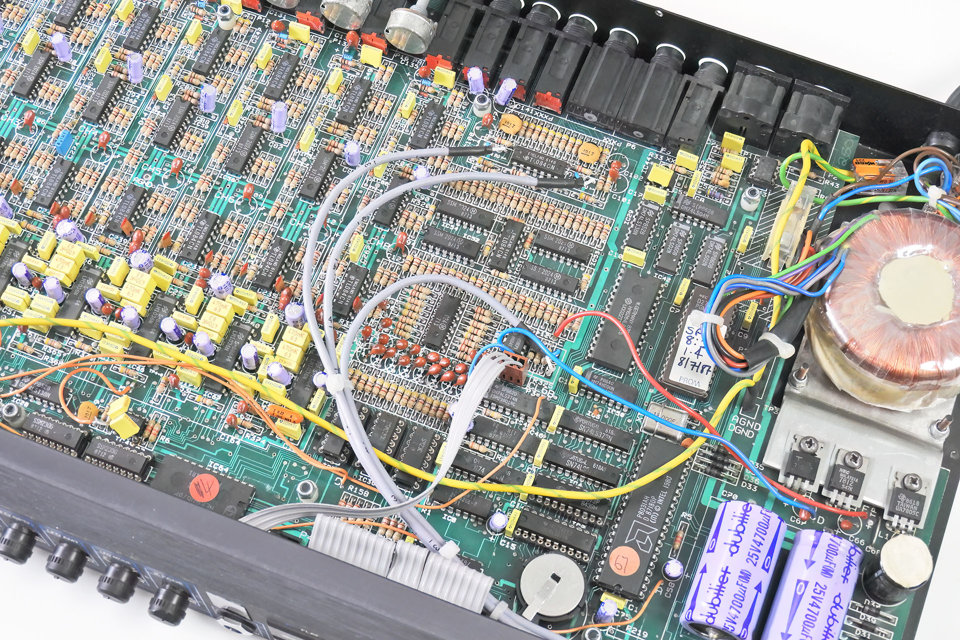
Anyone familiar with the insides of the SPM8:2 will notice three black cables coming from the front right to the middle right of the PCB. These cables carry analogue audio to and from, the volume and headphone potentiometers on the front panel and go straight over all the digital stuff. They also pass very close to the power supply.
Hmm... not good.
By the late eighties, Simmons was using a new type of cable for drum trigger assemblies. The new cable utilised a conductive polymer shield which provided a cost-effective and flexible solution. Well, they also used this cable for those signal-carrying lines in the SPM8:2, which mightn't not have been the best idea.
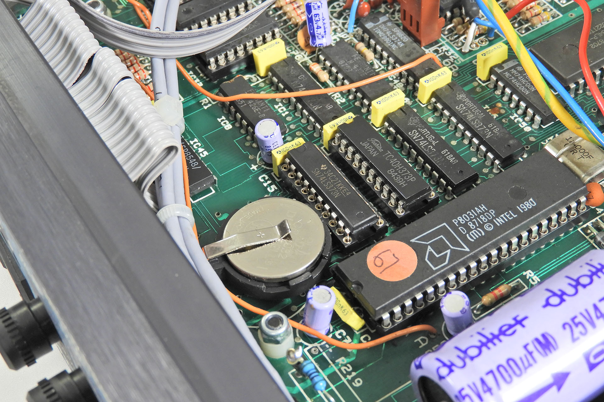
A few weeks ago, I pulled an old SPM8:2 out of storage. The thing hadn't been used for years so I thought I'd give it the once-over and see what I could do about that noise.
First things first. The Ni-Cd battery had just started leaking so it was quite fortuitous that I decided to do this when I did. I modified the circuit to take a lithium CR2032 and changed a couple of 74LS373 flip-flops that had suffered a little battery acid damage and weren't driving the 7-segment display and LEDs properly.
NOTE: I said "I MODIFIED the circuit". did NOT say "I just dropped in another type of battery". Go figure!
CAUTION: Please don't think you can swap out one type of battery for another. YOU CAN'T!!!!! It's a bit more involved than that.
Unfortunately but kind of as predicted, my battery leakage problems didn't stop at those two 74LS373s. Once powered up and with a fully working display and LEDs, flicking through channels and parameters, I couldn't find anything wrong but... I did notice some 'fur' around IC45 which is a 74LS175 (another flip-flop) and at least one broken track. IC46 multiplexes signals off the front panel pots. IC45 then feeds them onto a single buss.
Battery leakage is a killer. Luckily, this Simmons SPM8:2 didn't suffer too much as it was taken out of storage just in time.
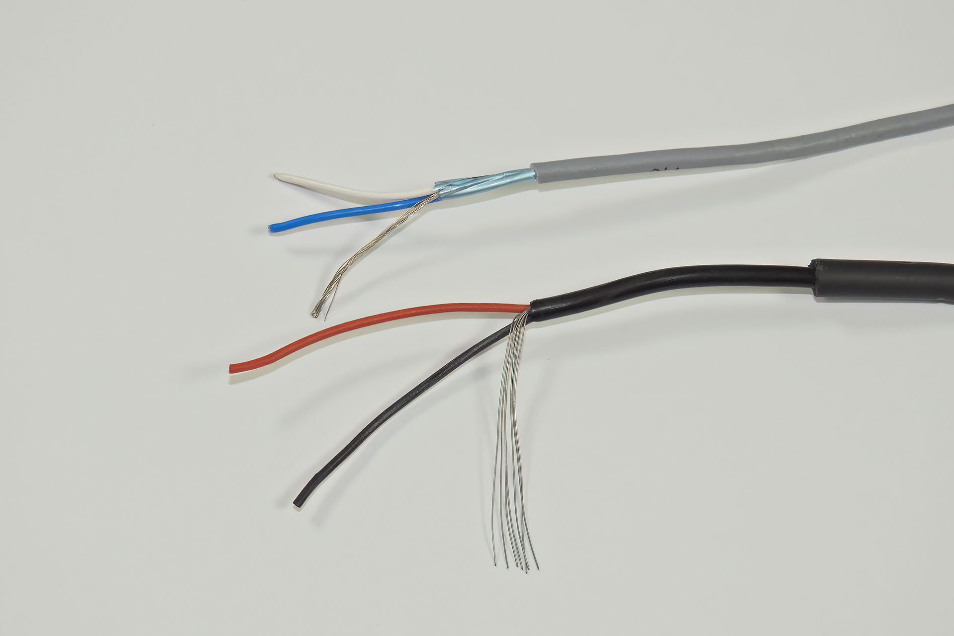
Okay, so in short, my Simmons SPM8:2 noise reduction mod entails replacing the original conductive polymer flying leads with fully shielded multi-core lines. The cables have a 100% metal foil shielding and in my humble opinion, would provide much better noise immunity than the stuff that Simmons used back in 1987.
My replacement metal foil shielded wires on top and the original conductive polymer shielded wires on the bottom.
Well, the results were quite startling as the replacement cables did indeed reduce the effect of all that digital chatter. My Simmons SPM8:2 noise reduction mod might inspire me to look into this a little further.
And here's what the mod looks like. It's really simple. You just need to take things easy.
The power supply in the Simmons SPM8:2 delivers +/-12V for the analogue. While quite adequate for connection of keyboards and of course electronic drums, the mixer can only operate at -10dBm. One option I'm looking into, is modifying things so that the SPM8:2 can operate at +/-15V. Right now, I'm not at all sure if that's possible but if it is, then doing so, may increase the signal-to-noise ratio, as well as making the outputs compatible with more modern destination devices running at +4dBm.
I think I'm also going to look at the earth on this box as apart from noise, the level of 100Hz (don't forget I'm in the UK so our mains is 50Hz), is more than I think it should be.
The nature of the noise, makes setting up a single-ended noise suppression solution across the outputs, somewhat challenging. With a little patience and careful configuration of the expander and gate sections however, it can be done. When material is playing through the system at normal levels, the noise is inaudible. It's just when things go quite, that you kind of think you can hear all those chips talking to each other!
I didn't expect my Simmons SPM8:2 noise reduction mod to work miracles but I have to admit to be being somewhat impressed with my modest efforts. I think with a little more work, this old Simmons MIDI programable mixer, might actually get some use. 🙂
The eighties was an exciting time for musicians and producers but the explosion of gear ironically left a few holes. In 1987, Simmons intended to fill one of those holes with the SPM 8:2 which ended up being used probably more by keyboard players than e-drummers. I myself had three or four of them, specifically as sub-mixers.
At 599 GBP it wasn't cheap but you have to remember of course, that it wasn't just an 8-channel mixer, it was programmable and that was a very welcome feature at the time. Why? Well ironically, one reason was that you could mute the sound sources that you weren't using in a particular performance and thereby... keep the noise level down! 🤣
Ushering in a new era which would soon become dominated by machines with controls that did several functions and even requiring users to press a combination of buttons to do perhaps, deeper tasks, the SPM8:2 was amongst the first to lose the ergonomics of the analogue box. Having said that, we seemed to be happy with the sacrifice of old ergonomics and musicians, engineers and producers quickly accepted the fact that now, they would have to 'learn' stuff!
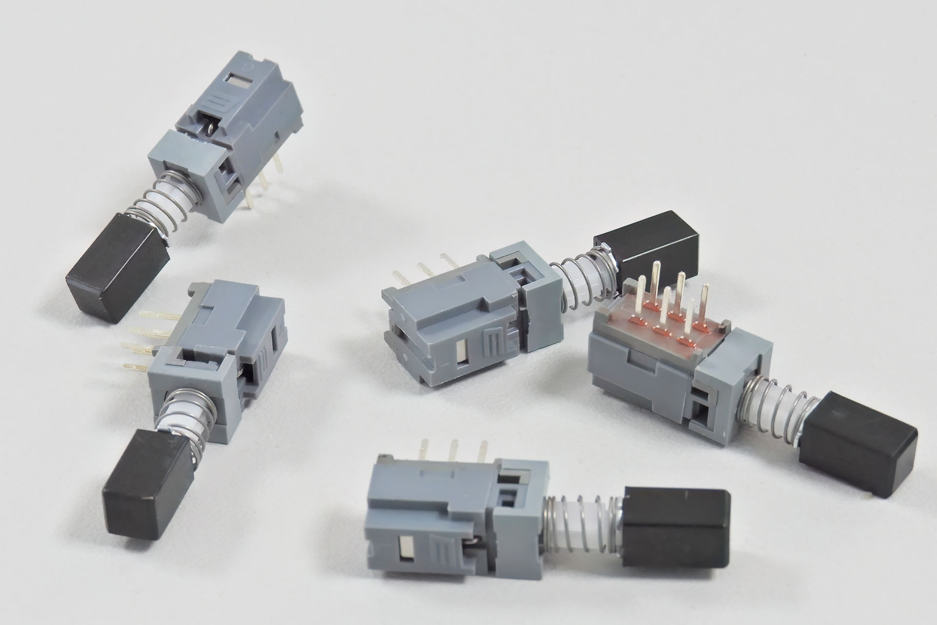
A replacement output level selector switch for the Marshall JMP-1, is something I get asked for quite a lot so after quite a bit of trial and error, I'm delighted to announce that a replacement is now available.
Geesh the originals were bad! The body of the switches that Marshall used comprised two separate plastic components that were 'clipped' together. Of course, the switch has a spring inside and it's quite common for this spring to pop, thereby making the switch body explode. Once that happens, it's kinda game over.
The body of this replacement Marshall JMP-1 output level selector switch is a single piece of tough plastic and the build quality makes it considerably more robust than the original.
Much more robust than the original, these replacement output level selector switches will last a long time.
Once the board is out, my drop-in replacement switch is easy to install and will last a lot longer than the originals.
The switches even come with the square shaped button already attached to the shaftbut... if you still have the original button and would prefer that, then you can swap the buttons over.
Currently, this is the DPDT version and is only suitable for the Speaker Emulated outputs and the Master outputs. Being a TPDT switch, the level selector switch for the effects loop is a little different but as soon as I find a replacement, I'll make that available too.
My switch is available to buy here:
If you have any issues with your Marshall JMP-1, please don't hesitate to contact me. 🙂
My town Hemel Hempstead, is twinned with Neu-Isenburg in Germany. In fact, I'm the chairman of the Town-Twinning Association here. Before Christmas last year, we were made aware of a European festival that was to be held in Neu-Isenburg and my family and I couldn't wait to go and meet up with some friends.
Then, a couple of weeks ago, the Burgermeister of Neu-Isenburg visited Hemel Hempstead and I was privileged not only to meet Gene Hagelstein but also to look after him for a couple of days during his visit.
Well, when I met Gene, with other council officials at The Forum here in Hemel Hempstead, it just so happened that Michael Buchner, a fellow member of the Simmons Vintage Technical Network and I were e-mailing each other. Apart from telling me that he lives only a few kilometres away from Neu-Isenburg, he also asked me to pass on his best wishes to Gene. SERIOUSLY?????
I told Michael that I was coming over to Neu-Isenburg the following week and we agreed to meet up.
Despite both being members of the Simmons Vintage Technical Network, this was the first time that Michael and I had actually met. Such a knowledgeable and experienced guy, Michael is also just a lovely person and I don't know why we hadn't done this before, especially considering the number of times that I've been over to Neu-Isenburg. I only wish I could have stayed longer but I'm sure to be back, Michael. 🙂 See you soon, buddy!
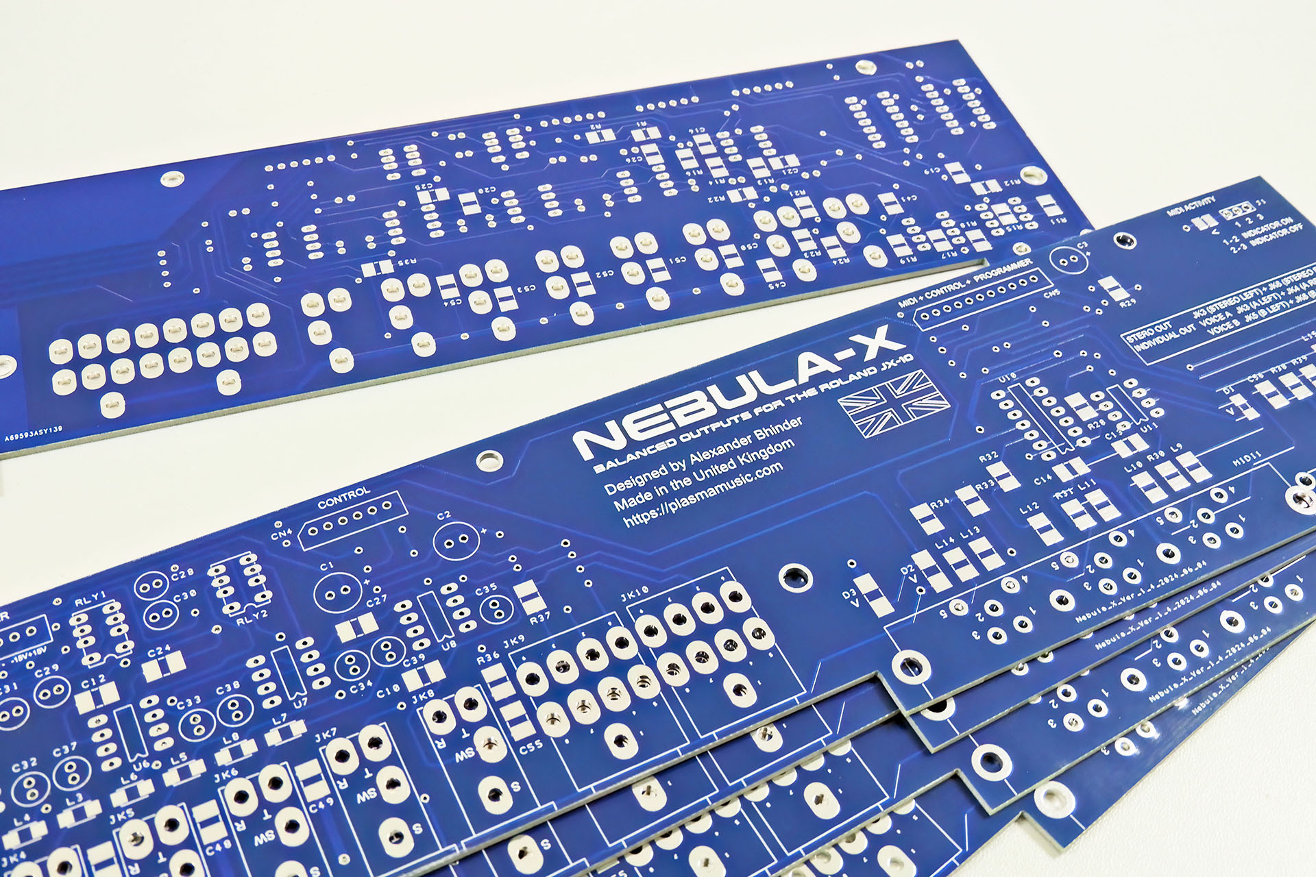
Yes, I'm very excited as my Nebula-X prototype PCBs have arrived! 😮
After developing Nebula balanced outputs for the MKS-70 in 2021, I received a lot of requests to do the same for the JX-10.
With considerably more issues to overcome and also wanting to address the noise picked up before the jack-board in the JX-10, I wanted to do more than just offer balanced outputs.
Like Nebula balanced outputs jack-board for the Roland MKS-70, Nebula-X is intended to provide balanced outputs for the Roland JX-10.
Since MIDI hardware resides on the jack-board and again, just like I did with Nebula, I've improved the MIDI circuitry using modern components.
Nebula-X under development.
Today my Nebula-X prototype PCBs have arrived so it's going to be a busy few weeks as I build this, make sure everything fits, test and confirm that the theory I'm implementing to combat JX-10 noise, actually works.
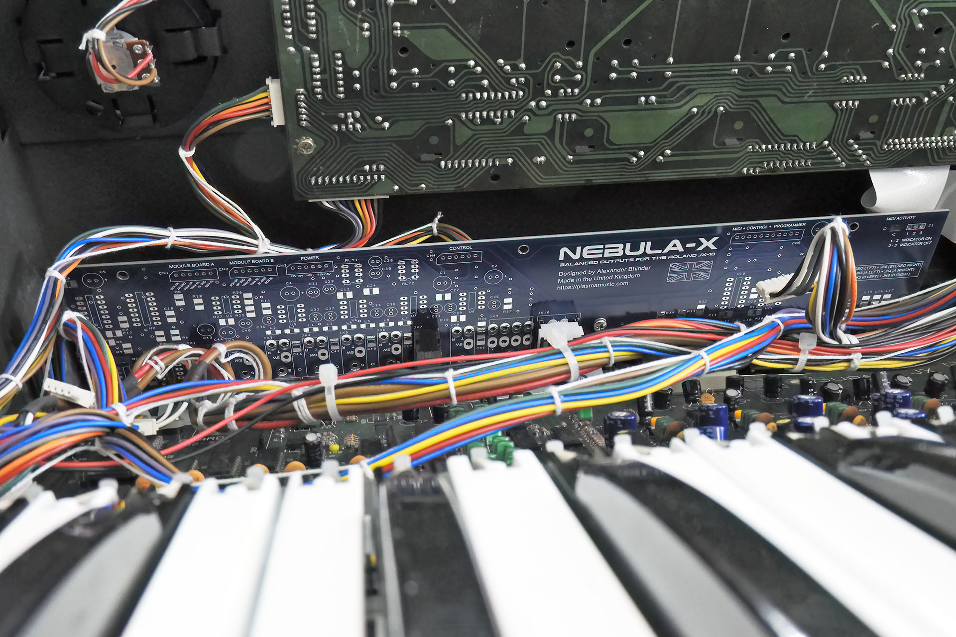
UPDATE - 8th June 2024
One big challenge with designing peripherals for vintage synthesisers, is the physical aspect of what you're doing. Designing electronics to work with older gear is one thing but making sure that what you have designed, actually fits, is another.
It's taken three attempts to end up with a Nebula-X PCB that actually fits. You measure, remeasure and measure again and you know damn well that despite having done this kind of thing many times before, it's going to take several attempts for the bloody thing to fit!
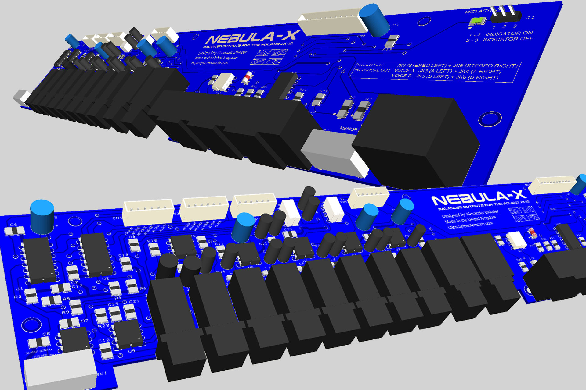
I made a slight departure with Nebula-X. Knowing that Nebula-X was going to be more expensive than Nebula MKS-70, I spent a long time researching components with a view to keep costs down. I didn't go for the original jack sockets, for example. Instead, I used a more readily available version. Still made by Jalco, they fitted perfectly. The programmer port was a similar story, as were the switches but I couldn't find a suitable substitute for the three-gang MIDI connector array. Luckily, that's still available.
As you can imagine, there were some compromises. Like Nebula for the MKS-70, the output level selector switch is replaced with a switch used to reconfigure Nebula -X to either deliver a stereo or individual outputs as this can't be done using the ingenious switching system that Roland employed back in 1986. The reason it can't be done, is because the switched versions of the 3-pole jack sockets that are needed to do that, are much wider than the 2-pole sockets and they simply wouldn't fit.
The other compromise is the programmer write protect switch. Unlike the original, Nebula-X uses a 2-position switch, simply due to the fact that I couldn't find a 3-position slide switch that fitted and matched up with the other switch. Things are much smaller now-a-days.
You'll also notice that the inside of the front of the jack sockets, have a metalised ring. The originals were all black but I think this will actually look pretty neat when it's finished.
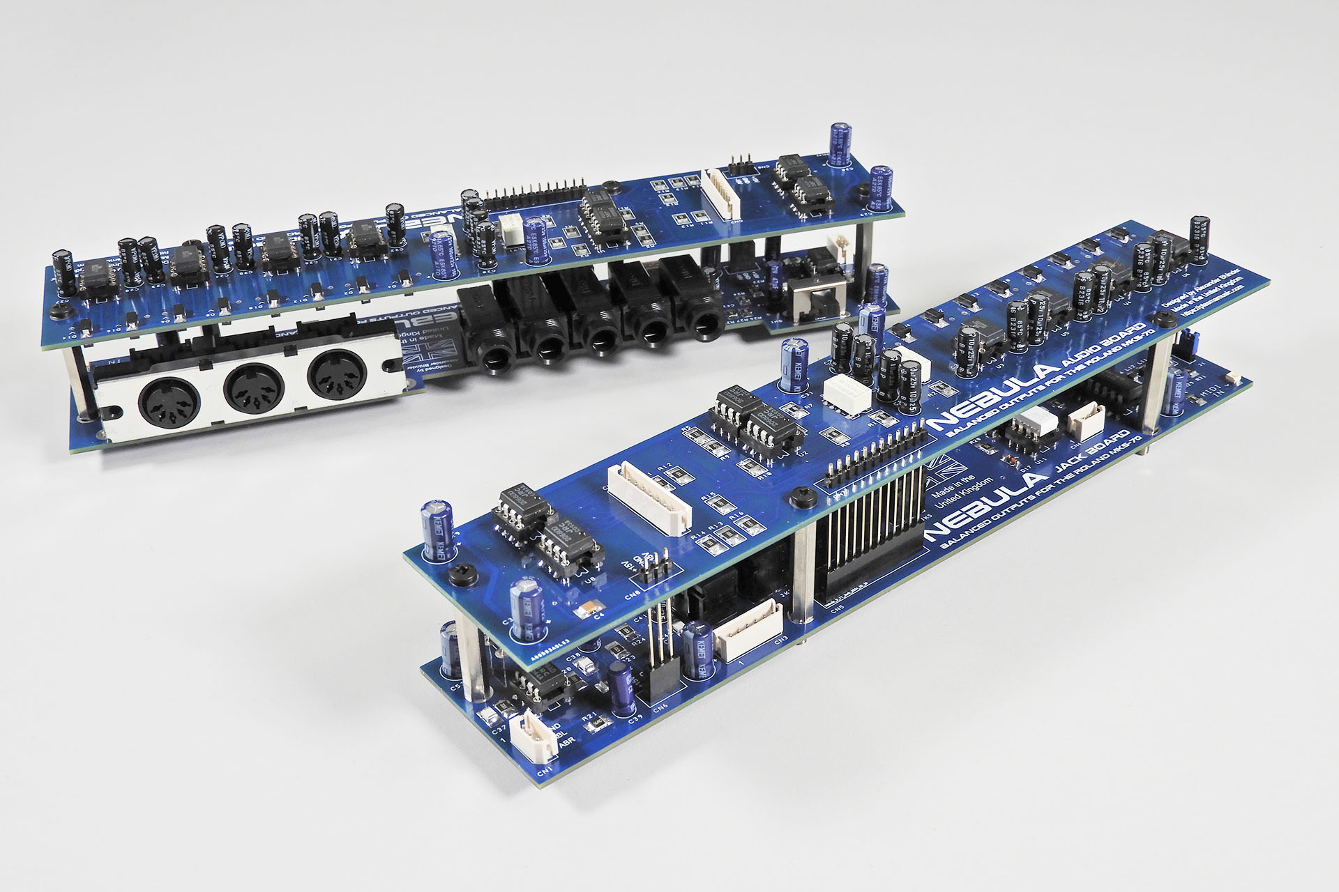
UPDATE - 25th August 2024
Hey, I finally got around to building the first Nebula-X prototype and it looks magnificent, even if I say so myself.
Over the past few weeks, I've been working hard to finish a whole load of stuff I've designed for the Simmons SDSV and Simmons SDS7. Alas, Nebula-X was left on the shelf.
While getting over a summer chest infection, I took things easy, put the Simmons stuff aside and well, I couldn't help myself. That Nebula-X PCB was watching me. 🙂
I'm still working on my Simmons bits 'n' pieces but it won't be long now before I can start putting Nebula-X through its paces.
This Simmons SDS7 battery leak occurred because the battery wasn’t charged regularly.
Recently in, was a Simmons SDS7.This is my second most favourite electronic drum systems of all time, after the Simmons SDX. In fact, you can read how much I love this instrument here.
Anyway, this SDS7 was apparently just fine a couple of years ago but when the owner recently got it out of storage, there was no sound. Powering up but otherwise completely dead, only the voice-card name illumination seemed to be coming on with nothing showing in the programmer display. Well, I had a pretty good idea what was wrong with it.
Like a lot of music technology at the time, the pre-MIDI Simmons SDS7 used NiCd (nickel-cadmium) batteries to back up its memory. Some manufacturers like Cheetah, continued to use NiCads all the way up to the end of the eighties, perhaps even a little later. Unlike lithium batteries which soon took over, NiCads need to be regularly charged. If left uncharged for an extended period, NiCd batteries die and WILL LEAK.
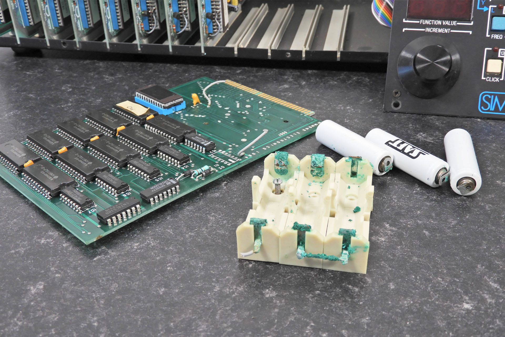
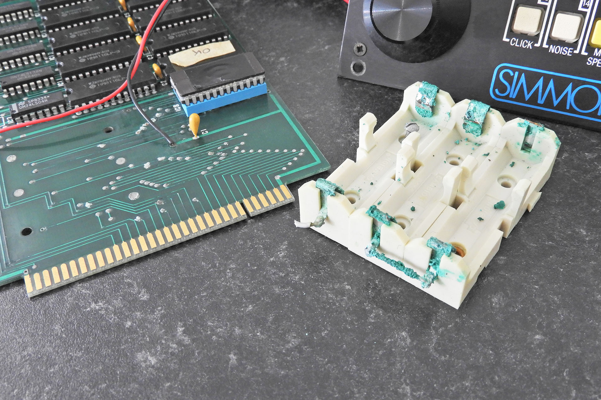
Fortunately, the Simmons SDS7 was built with vertically mounted PCBs. Despite the fact however, that there was also a version (like this one) which, instead of having a single battery soldered directly to the memory-board, used a triple AA battery holder (3 x 1.2V in series = 3.6V), battery acid managed to leak out over those already old solder joints, tracks and components. I soon noticed for example, that the C̅E̅ line was down and in fact there were several other issues preventing code from running and therefore not allowing the machine to boot.
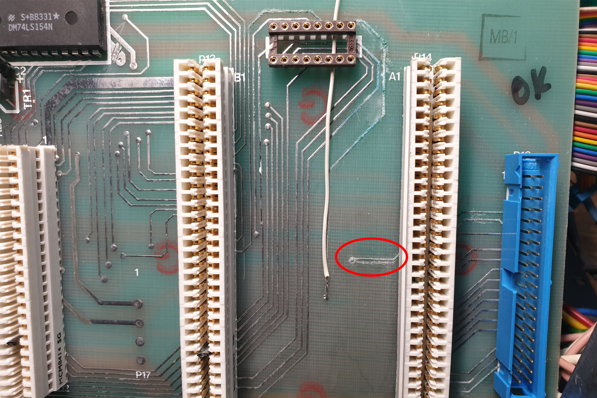
There was also, a fair bit of damage to tracks on the rear buss-board (marked up as 'SDS7 BACK PLANE'), which couldn't be resolved by cleaning alone and which required some hot-wiring. Annoying but to be expected.
Although the memory-board was okay, some tracks were badly damaged on the rear buss PCB. The one highlighted in red had completely perished and only the white trace was left.
Above you can see that I'd already jumped one track but there were another eight which although buzzed out okay, I really didn't like the look of. One in particular looked as though it had completely succumbed to battery acid.
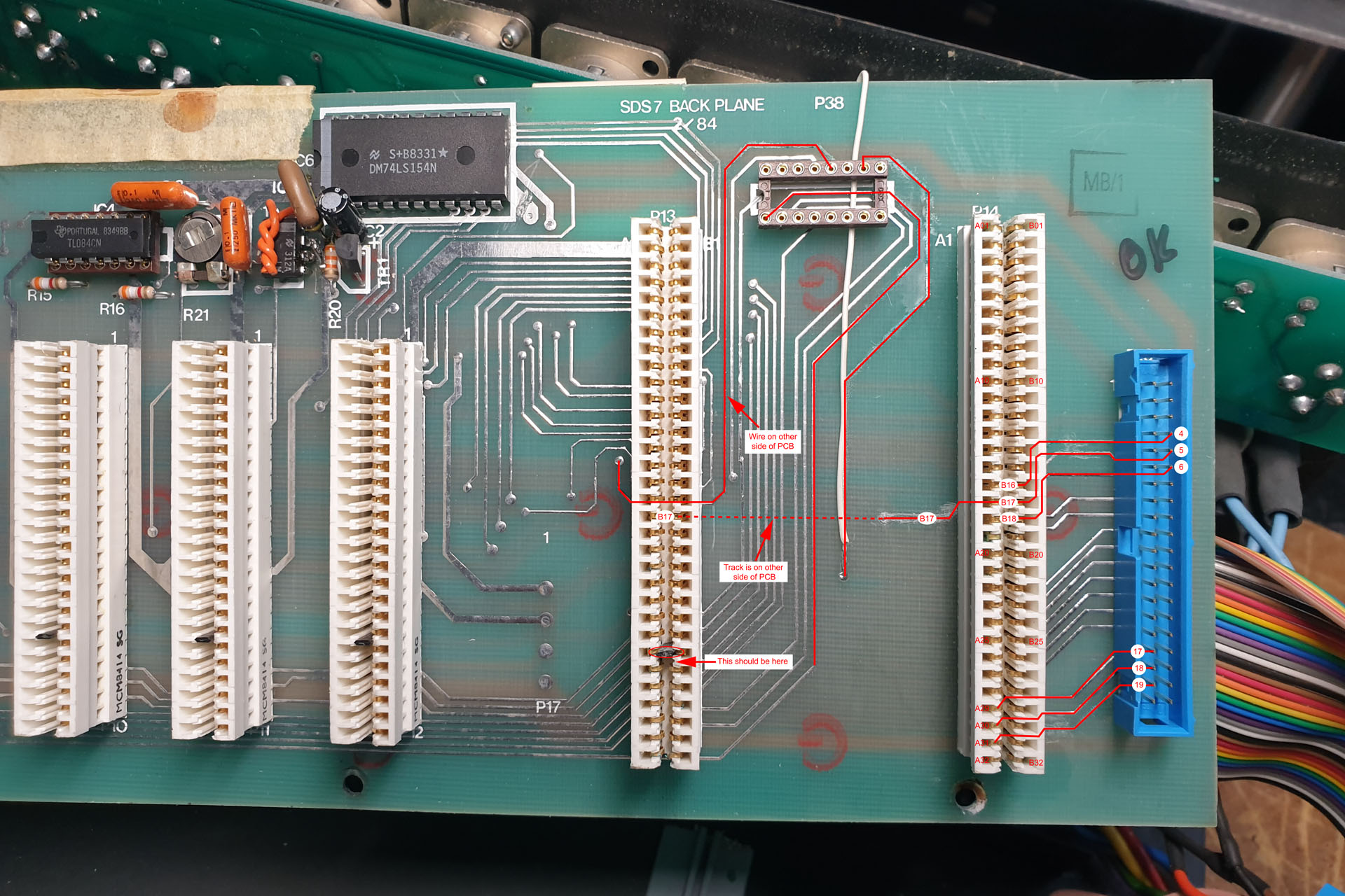
Technical literature on really old machines like the SDS7 is thin on the ground. Techs often have to make do with copies that were scanned many years ago on what would now be classed as, low-resolution scanners. I therefore, decided to make myself a little reference diagram.
Unlike the image above which is a standard 1920 x 1280, the original pdf document is pretty big but without going to that kind of trouble, I'd be shooting in the dark. In the end, I actually decided to install my wires around the back of the back plane PCB.
You'll notice in the two images above, that the polarising key in the CPU card edge connector (P13) is somewhere where it shouldn't be and that the key in the edge connector to the right (that takes the memory-board) is missing altogether. In fact, there was a polarising key on one of the voice-cards that was also out of place and so the card didn't work properly.
Anyway, while I was buzzing things out on the back plane, I carried on cleaned up the memory-board.
The battery holder can't be salvaged but I have other plans anyway. I've made a start on cleaning up the memory-board. You may notice that I changed the two grey battery wires. They are now colour-coded!
When I say "cleaning up the memory-board", it actually took several days to buzz out connections and hot-wire tracks that had been damaged by battery acid. After all that, this SDS7 finally managed to consistently boot but there was another problem; the data encoder was unresponsive. Grr... The problem turned out to be a simple but very annoying, dry joint under a buffer that reads the signal off one of the optical receivers. Phew...
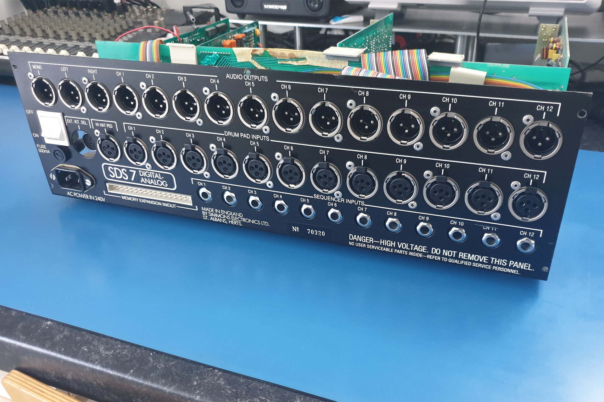
My own SDS7 is serial number 71722. The serial number on the back of this one was #70320. If sequential, that's 1,402 units difference. More than just a batch or two!
Indeed, as I went over the insides of this SDS7, it became apparent that it was quite an early version. It had the optical encoder as opposed to the electrical contact type. The polarising keys in the edge connectors on the back plane were the small bits of black plastic type, instead of the yellow clip types used later. There were also various wire jumpers on the CPU-board that aren't on later revisions.
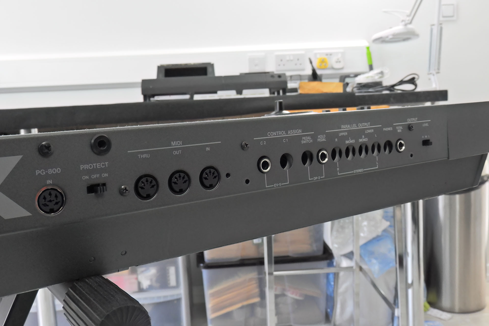
On a side note... There was also some work to do around the back of the unit as the socket pins although not corroded (because they can't), were very black and so needed a good clean.
The XLR pins on the audio outputs were black so needed a good clean. I think I'm also going to have to do the XLR receptacles on the pad inputs.
The lid was smacked in at the front and was also badly scratched and lots of areas that showed corrosion.
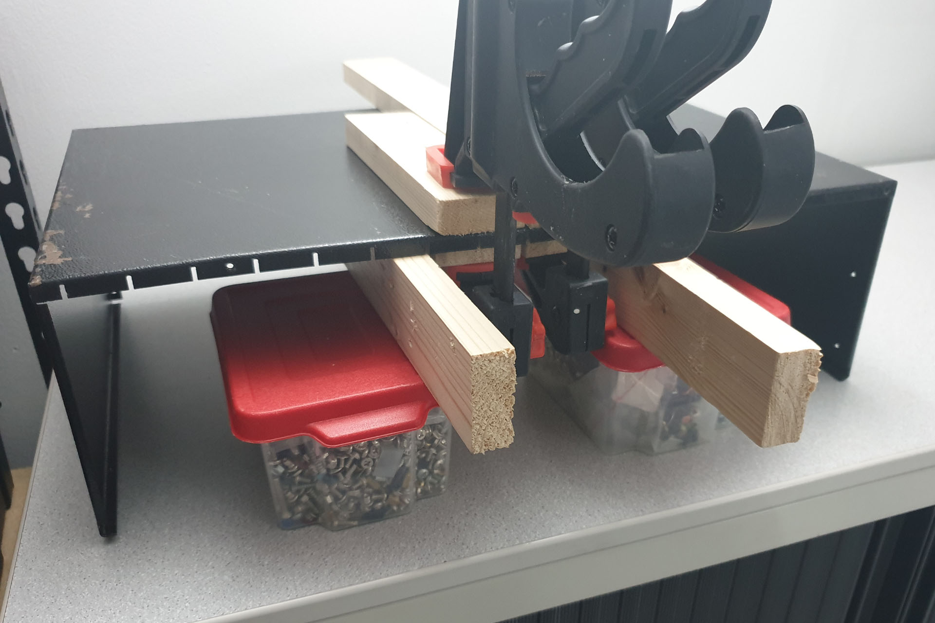
Removing the creases on a piece of metal like this is a time consuming task but it'll be worth it. This SDS7 is otherwise in pretty good cosmetic condition.
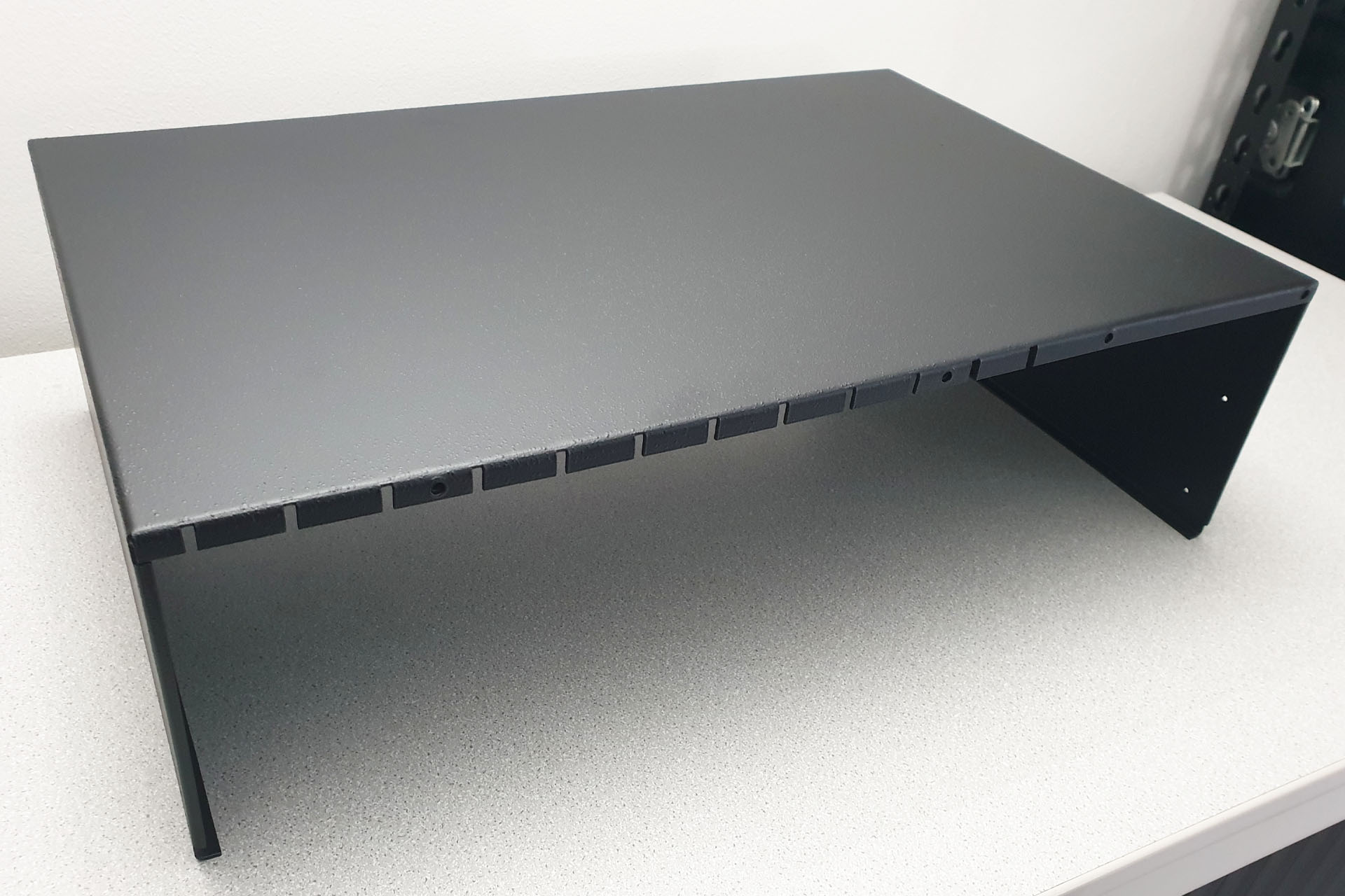
After several days (or perhaps two weeks) of patient straightening with a combination of heat, G-clamps and weights, I took it to a local company to be sand blasted and powder coated. They said that they didn't think they'd be able to match up the leatherette finish but when I collected the lid a week later, I was blown away. This top case looks like it just came from the factory! WOW!!!! 😮
I was absolutely delighted with the results of sand blasting and powder coating this old Simmons SDS7 top case. It wasn't just the colour. They got the shade and texture bang on. THANK YOU Chiltern Blast Cleaning!
So, back to batteries... Amongst instruments like the afore mentioned Cheetah MS6 and true vintage gems like the Sequential Circuits Prophet V, a Simmons SDS7 battery leak is something I've seen quite a few times over the years, or should I say decades. Don't think that everything can be fixed. It took me two years to concede that the last Prophet V I had in with a leaked battery wasn't salvageable. It's incredibly sad and something that would potentially 'brick' an iconic piece of vintage music tech' so please take note: If you have a piece of old gear like this, do check what kind of battery it has. If it's got a NiCd battery, then make sure it's charged regularly.
! ! ! WARNING ! ! !
Floating around on the Internet, is a post of someone who's substituted a NiCd battery with a lithium battery in (coincidentally), a SDS7. PLEASE DO NOT DO THIS!
Memory retention is designed for specific batteries. The chemistry of a lithium battery is very different to that of a NiCd battery. For a start, the former can't be charged and if you try to do so, you may end up with getting more than your fingers burnt... literally.
For over thirty-five years now, equipment has been designed to take batteries like the CR2032 which we're all familiar with and which outputs 3.0V. Older NiCd batteries are rated at 3.6V. That 16.7% difference can sometimes be significant.
You should also double check when buying batteries as many unscrupulous or perhaps just ignorant retailers advertise NiMH (nickel metal hydride) as NiCd and lithium-ion as lithium. In all fairness, sometimes it's just not clear. As we all know, a Google search for example, will often throw up results that are close to your search term so please check before you buy. Yes, I know it's frustrating, especially when NiCd batteries are becoming increasingly more difficult to procure but please don't be tempted to take the easy option. Batteries are all different. Even those that can be charged, have different charge rates, depending on their respective chemistry. Charging circuits for NiMH batteries for example, are usually designed to measure the status of the battery, thereby dynamically reducing the current that's being fed into them. This is NOT the case with NiCd charging circuits. If you substitute NiMH into a system that normally takes NiCd, then you stand the risk of overcharging the battery. This might not be disastrous but will reduce the lifespan of the battery.
MY APOLOGIES TO SELLERS
If you're considering buying a Simmons SDS7, please do also consider asking the seller to show you a picture of the memory-board. My apologies in advance to anyone selling a Simmons SDS7.
AND FINALLY...
It's quite difficult to find information on the Simmons SDS7 and so I thought it prudent to offer some useful links for those interested.
For a start, if you're in the US, you need The Simmons Guy on your side. Ed is not just knowledgeable and experienced, he's methodical, tidy and VERY helpful. Just one thing; because of all that, he's amazingly busy!
Ed (The Simmons Guy) is also very active on social media and it's worth checking out his Facebook page and his YouTube channel. In fact, in amongst his videos, you'll see my own SDS7 #71722 before I bought it from him, LOL. Ed, where on earth do you get the time?
This site has a lot of really useful SDS7 information and may be of help to those who just need a few facts.
And of course, there's the Simmons Virtual Museum which also has a few useful resources.
UPDATE - 30th May 2024
Since writing this article, I'm delighted to advise that the SDS7 featured above, is now fully up and running! 😀
It took a while and as I focused my attention on the memory-board, actually there were a couple of tracks on the back plane that slipped my eye. Grr...
Since posting however, I've had a few more older items in with completely leaked out batteries.
If you think they look bad, then you wouldn't want to see the insides of the machines that these all came out of! One of them had to be scrapped as it was totally unsalvageable.
I've been toiling with the idea of replacing the static 8k x 8 RAM in our favourite MIDI valve pre-amp with a non-volatile SRAM (nvSRAM) for long time, now and I'm delighted to report that after a lot of work, including testing over recent weeks, my Oracle battery eliminator for the Marshall JMP-1 is finally here.
I understand why batteries were used to back up machine memory in say the late seventies and eighties and even in the nineties but now-a-days, it all seems totally unnecessary. Could it possible to integrate modern nvSRAM technology into a machine that's more than thirty years old, though?
Modern machines don't have batteries. Many will be familiar with my love of the Behringer DEQ2496 Ultracurve Pro, which is an example off the top of my head, of a machine that doesn't have battery backed-up memory. Indeed, when I say 'modern', please consider that at the time of writing this, the DEQ2496 is more than fifteen years old!
This fifteen year old Behringer DEQ2496 UltraCurve Pro doesn't have battery backed up memory.
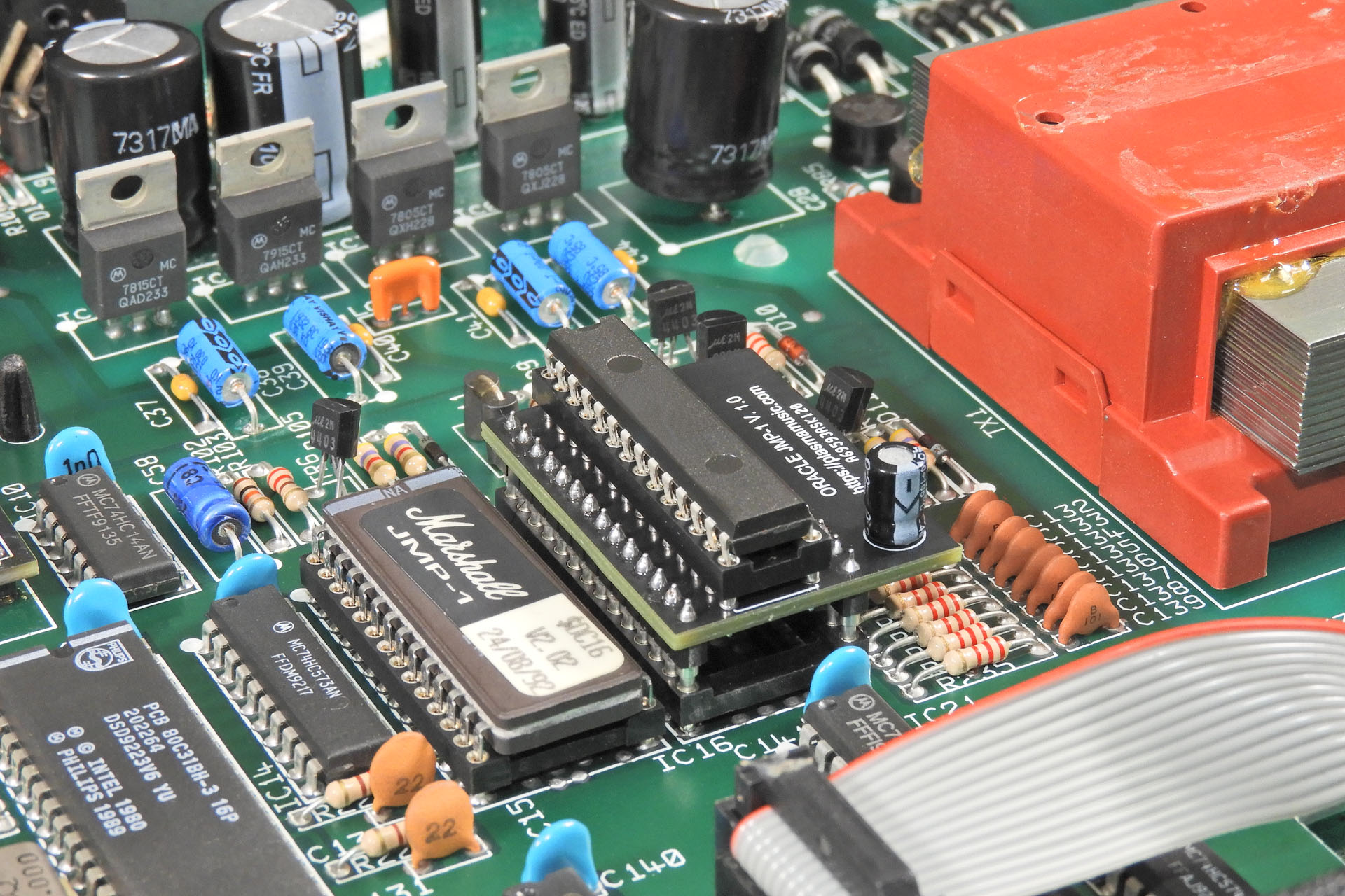
CPU control in the JMP-1 is typical of the time. Although I know this machine inside-out, it was still worth double-checking, just to make sure I hadn't missed anything. Indeed it was obvious that other than removing the battery, no other modifications were necessary to implement Oracle.
The CPU controller side of things in the JMP-1 is very typical of the time.
Look, no battery means that you'll never have to worry about losing your pre-sets and more importantly (perhaps) is that a battery won't leak if it's not there! Oh wow... peace of mind all around. That's exactly what my Oracle battery eliminator for the Marshall JMP-1 was intended to achieve.
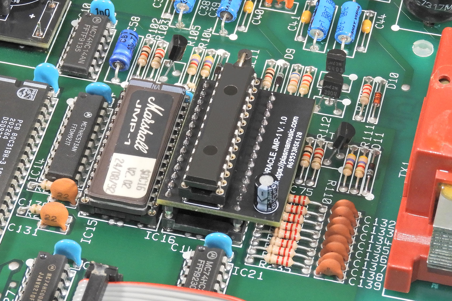
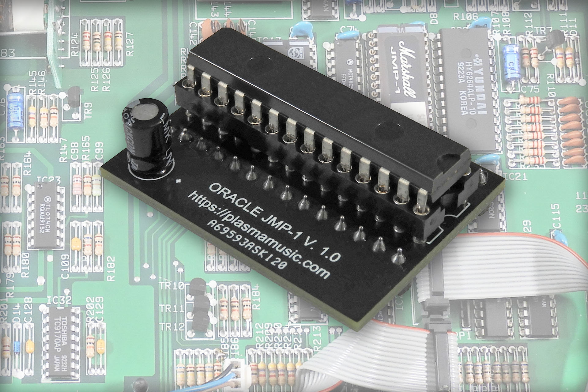
Well anyway, a few months ago, I decided to just do it and so I've developed a little kit which involves replacing the Hyundai HY6264 SRAM chip inside the JMP-1, with a snap-in PCB which has few components on it and which means that you can pull out your battery and lose it. "Seriously?" Yes, SERIOSULY!!!!
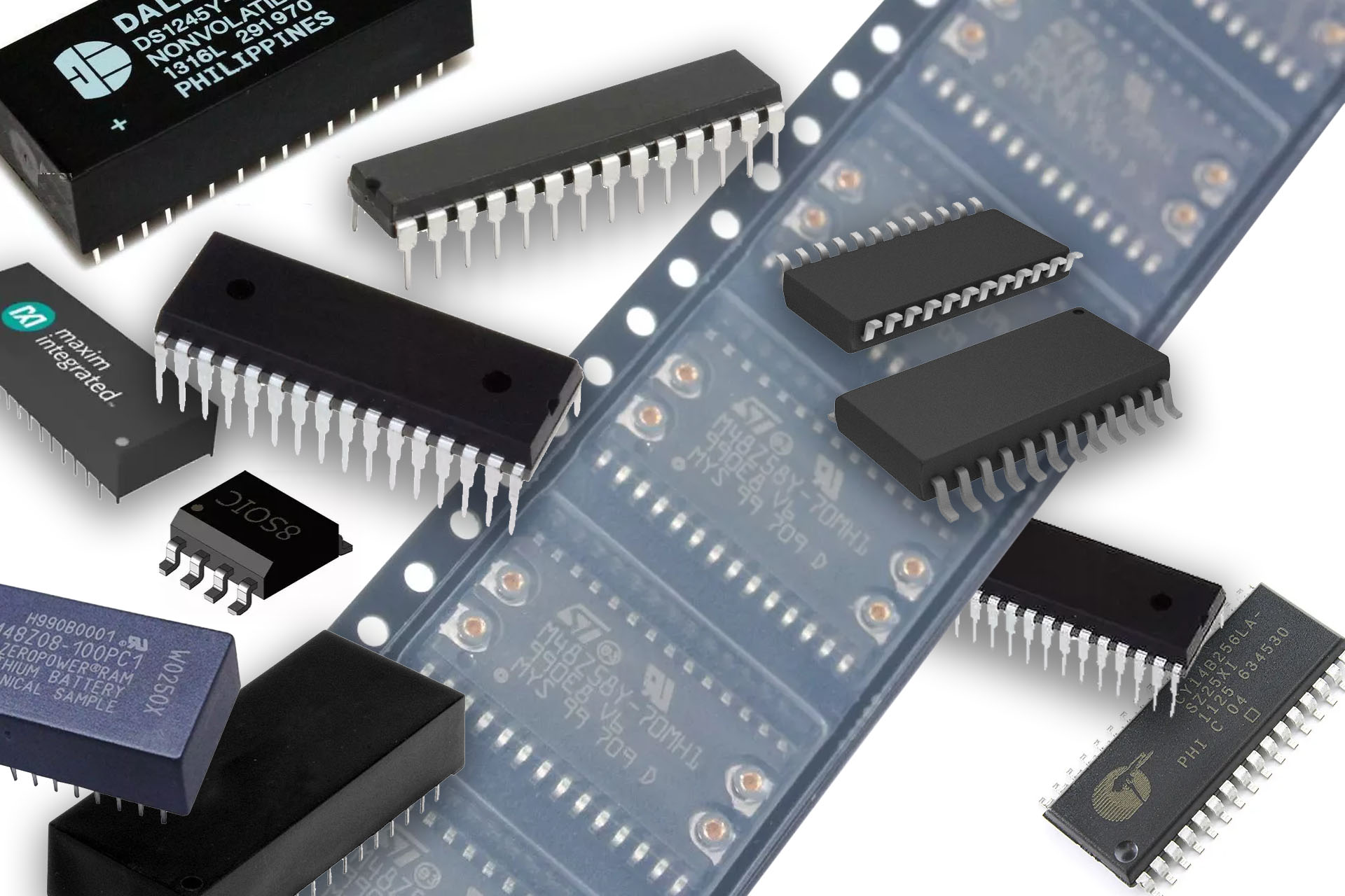
So the real challenge wasn't finding a suitable nvSRAM chip. Oh no, there are loads out there. Unfortunately, many of them still rely on batteries but instead of an external battery, the battery is built into the chip, which... kind of just moves the problem from one place to another. Those that don't however, are either much larger than 64k or simply aren't pin-for-pin compatible with the SRAMs of yesteryear, or both. Hey, I got there in the end! 🙂
The Oracle JMP-1 kit includes a 28-way turned-pin IC socket, so once the original device is removed, all you have to do is solder in the socket and drop in Oracle. This is a great option because it allows you to return your JMP-1 to factory hardware at any time, by simply pulling out Oracle and installing a Hyundai HY6264 or equivalent SRAM IC.
SO HOW DOES ORACLE JMP-1 WORK?
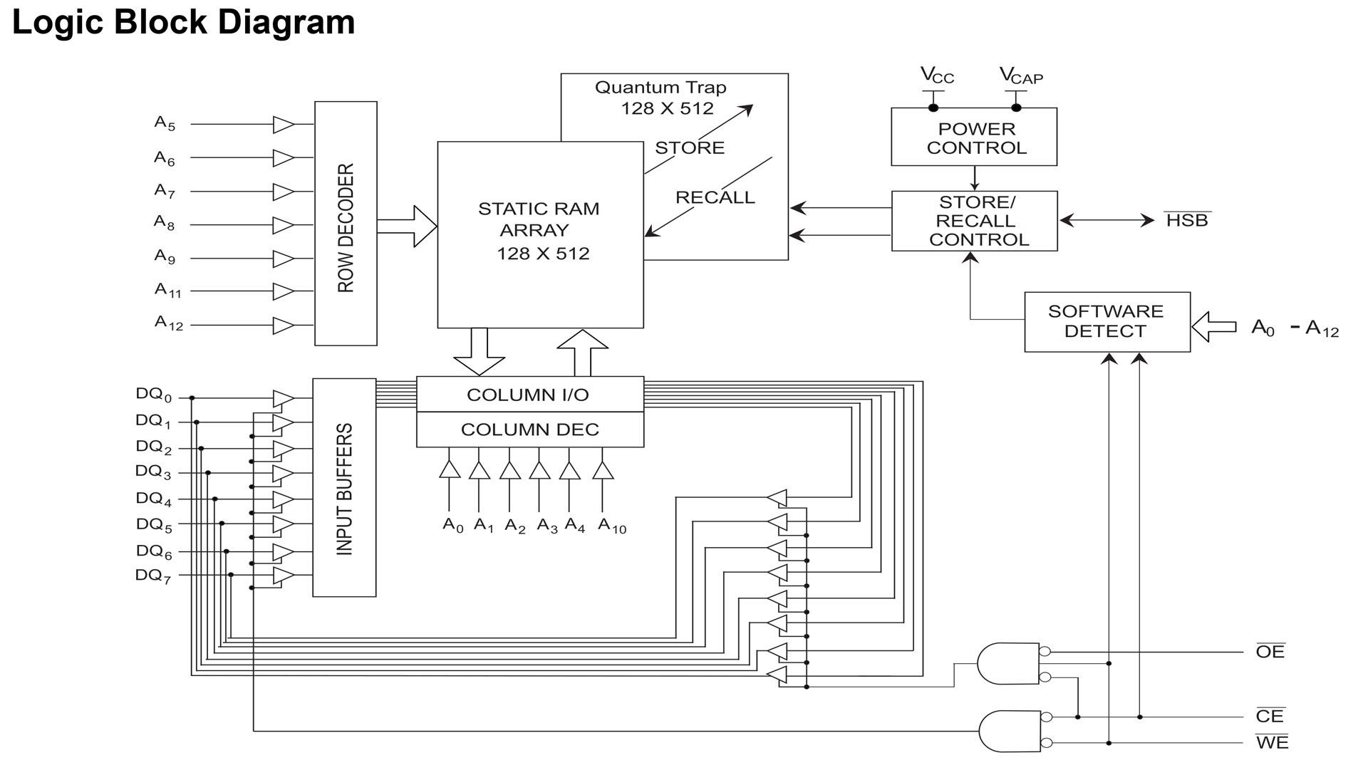
Okay, so it's not magic. At the heart of my Oracle battery eliminator for the Marshall JMP-1, is an IC that uses something called quantum trap technology (well, perhaps it is magic). Fundamentally there are two parts to the IC; a conventional static RAM (SRAM) like the original Hyundai Hy6264) and an Electrically Erasable Programable Random Access Memory (EEPROM). When switched on, the SRAM fires up and reads and writes data as one would expect, like nothing's really changed. The data that's in the SRAM however, can be written into the EEPROM. This is done by one of two methods; either in software or by specific hardware configuration, the latter of which has a two or three options. Well, I wasn't going to try rewriting the JMP-1's firmware so the autosave hardware configuration seemed to be the obvious way to go. Oracle JMP-1 is set up to retain memory when your JMP-1 is switched off. Isn't that just so cool?!?!?
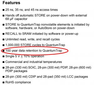
Oracle JMP-1 retains memory for a hundred years.
Of course, Oracle won't retain your JMP-1's memory indefinitely. Nothing lasts forever, right? It will however, keep your pre-sets safe for a very long time. Opposite is an extract from the nvSRAM device's datasheet and amongst the features, the manufacturer quotes a 100 year memory retention.
Just above that specification, you'll also notice that the datasheet quotes a million save cycles. What that means is that if you switch your JMP-1 off twenty-seven times a day, the nvSRAM chip will work fine for a hundred years!
I'm not quite sure how we're going to check those specifications. I'm definitely not going to be around that long. On the other hand, if they're correct, Oracle JMP-1 will last a lot longer than several CR2032s!
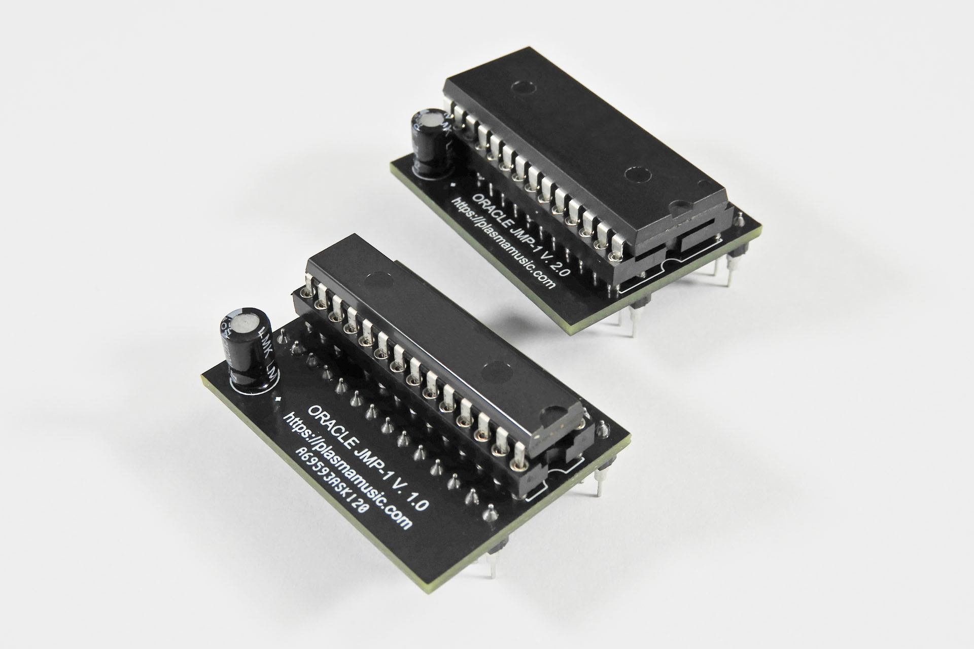
As I've already said, I checked out a whole bunch of devices that would be suitable for my Oracle battery eliminator for the Marshall JMP-1. With very specific technical criteria in mind, price was also going to be an important factor, especially if I was intending to release Oracle as a commercial product, . Trying to satisfy all requirements, I actually settled on two versions of the same device. Technically they're identical but one has a physical form factor of a 300 mil (7.62mm row spacing) 28-pin DIP IC and the other is packed into a 600 mil (15.24mm row spacing) 28-pin DIP IC. Yes, you guessed it, the 'slim' version is much more expensive. Not being sure whether or not using the higher-cost IC would be sustainable, I ended up designing two PCBs hence, V. 1.0 and V. 2.0.
Oracle V. 2.0 uses a 600 mil 28-pin DIP IC but the PCB is only 2mm wider than Oracle V. 1.0.
For the time-being, both versions will be available but I have a feeling that I'll have to phase out V. 1.0, due to cost.
So just to be clear, the two devices are functionally identical. The choice of whether you have Oracle with the narrow-body or the wide-body IC is entirely subjective and is NOT dependant on the SRAM or anything else inside your Marshall JMP-1
I'm a stickler for detail and I also believe in preventative action so apart from Oracle JMP-1 being supplied with a high-quality turned-pin 28-pin IC socket, it also comes with a small 4mm rubber pad with double-sided tape on one side. This gets stuck on the bottom your JMP-1 PCB, underneath Oracle, or rather the supplied IC socket. Why? Well, I'm just a bit worried that in all the excitement, it would be quite easy to just press Oracle into place a little too hard! The rubber pad will supply some support and prevent damage to the JMP-1 PCB. 🙂
There's another slightly less obvious benefit to Oracle; since your JMP-1's memory, i.e. your pre-sets, MIDI mapping, etc are stored in a device that doesn't need a battery, guess what? You can pull Oracle and drop it into another JMP-1 and all your stuff will be as it was but in the new box! Coolamundo, dudes! 😮
My Oracle battery eliminator for the Marshall JMP-1 joins my growing arsenal of bits 'n' pieces that I make for one of the best guitar pre-amps ever and having a Marshall JMP-1 with no battery, well it's just seriously cool! 😀 You can check out all my Marshall JMP-1 stuff here.
After a lot of testing over several weeks, I'm delighted to announce that my conclusions confirm that Oracle JMP-1 works just great.
Oracle JMP-1 battery eliminator for the Marshall JMP-1 is available to buy here:
CR2032 BATTERY ADAPTER FOR THE MARSHALL JMP-1
Back in July 2023 (like only nine months ago), I released a CR2032 battery adapter for the JMP-1. I had to find it slightly amusing, that I decided to follow up on my idea of Oracle so soon after I'd launched this adapter. Typical!
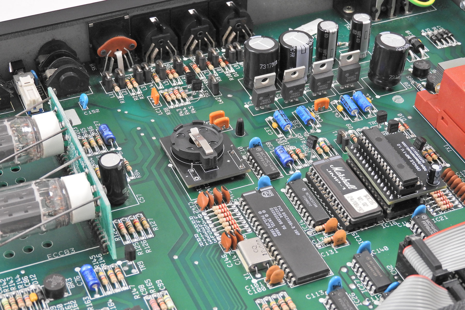
The image below is of my 'lab' JMP-1. It's used to test stuff I make for the JMP-1 before I send it out to customers. As you can see, Oracle JMP-1 is installed as is my CR2032 battery adapter... less the battery, of course.
My lab JMP-1 with both my CR2032 battery adapter and Oracle. Of course, the former is now empty. Who needs a battery when you have an Oracle?
My CR2032 battery adapter will remain available as I fully accept that swapping out that big SRAM IC for Oracle JMP-1, isn't going to be everyone's cup of tea. You can read more about it here.
Okay so, I'm sure folks are thinking "Why Oracle JMP-1? Why not just Oracle?" Well, I'm currently developing similar devices to eliminate the necessity for battery backed up memory for other machines. Some of those machines for example, don't even have 64k RAM and therefore use a 24-pin nvSRAM device. Also, component layout and PCB size may vary so as to fit.
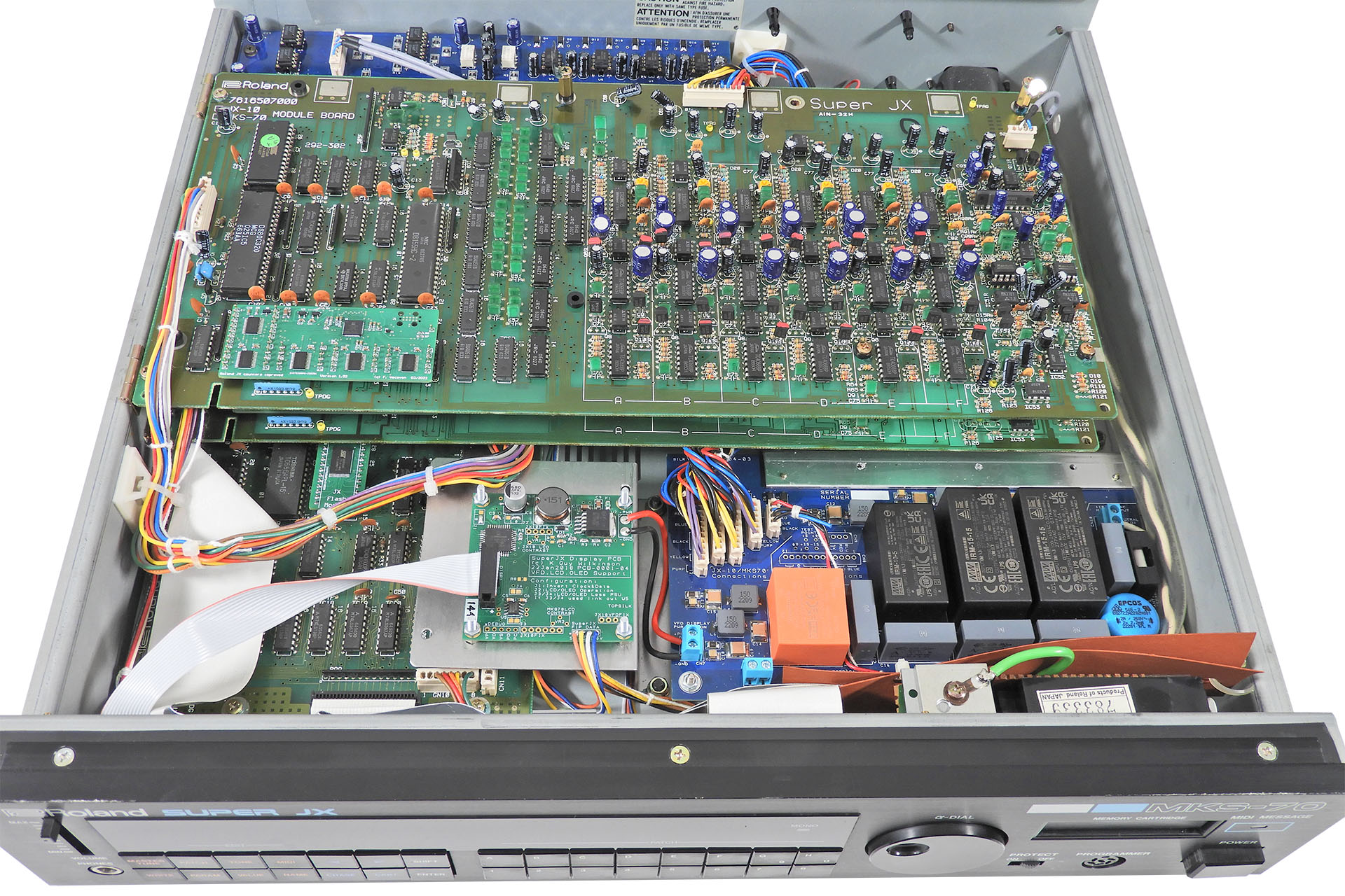
Yes, you read correctly. A lovely customer in Miami, who I've got to know rather well over the past couple of years, sent me his beautiful synth module asking me to put everything into it. I have a few of these come in on a regular basis from the US but on this occasion, I can't think of anything that the customer didn't ask for so ended up doing a Roland MKS-70 full upgrade. Of course I couldn't help myself and while I had it, Brent's MKS-70 got referred to as 'The Miami Sound Machine'. 😀
Brent couldn't find a good deal on shipping so I arranged for his instrument to be collected on my DHL Express (import) account. Yes, it's a little extra work for me but I know that the package will be looked after, I won't pay import duty and Brent would only pay duty on the work done (and not the MKS-70 itself), when it's returned to him. 🙂 Above all, it was considerably cheaper than anything he could find locally.
Yeah, I know so if you're in the US or Canada, then you're busting to know, right? Well, the cost of shipping The Miami Sound Machine from Florida to Hemel Hempstead, UK was less than 180 GBP and the package was here in three days. Brent couldn't guarantee he'd be in when DHL was scheduled to collect so he took it to a DHL depot. Be warned however. If you do that, DHL will most likely open the package for security reasons (fair enough).
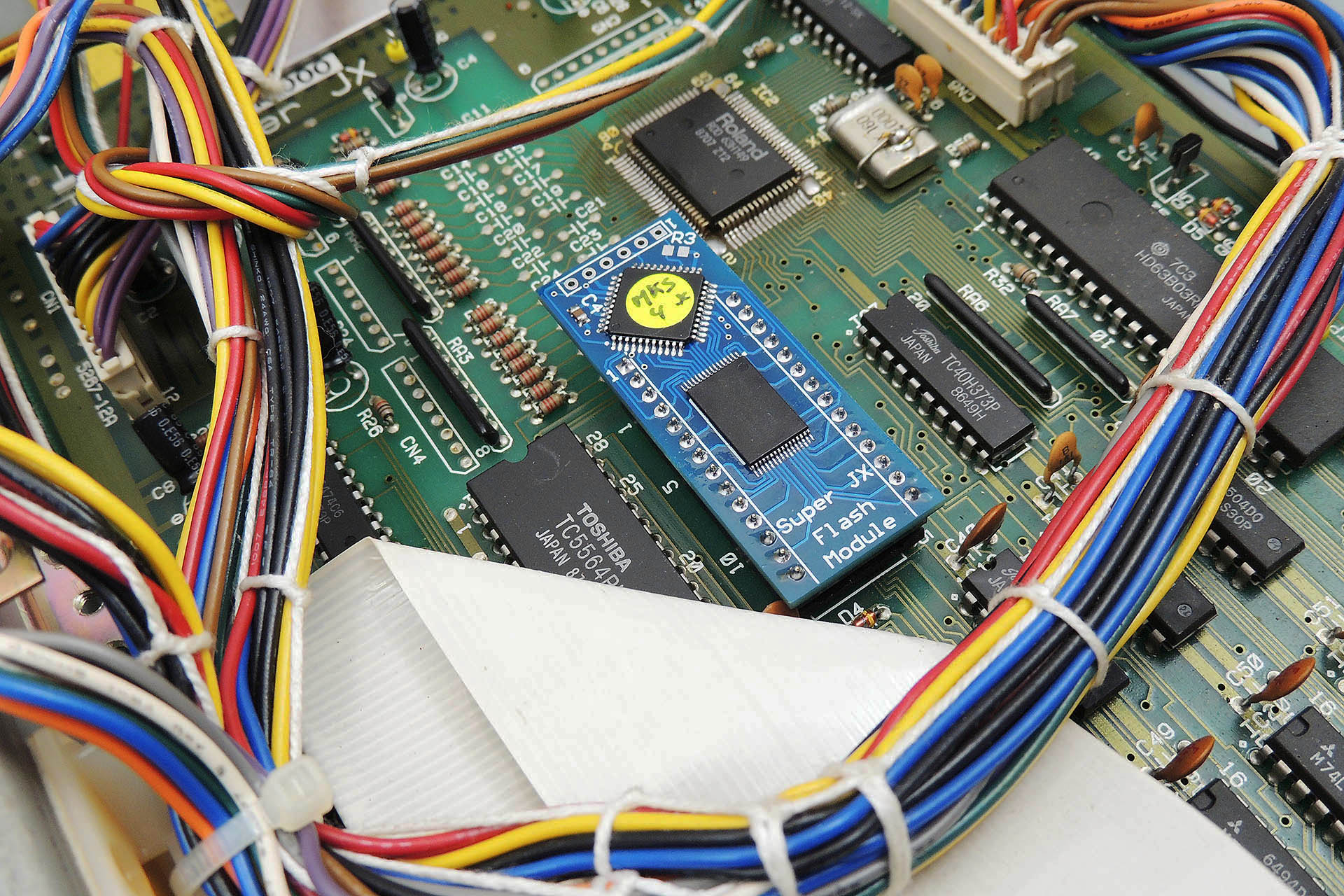
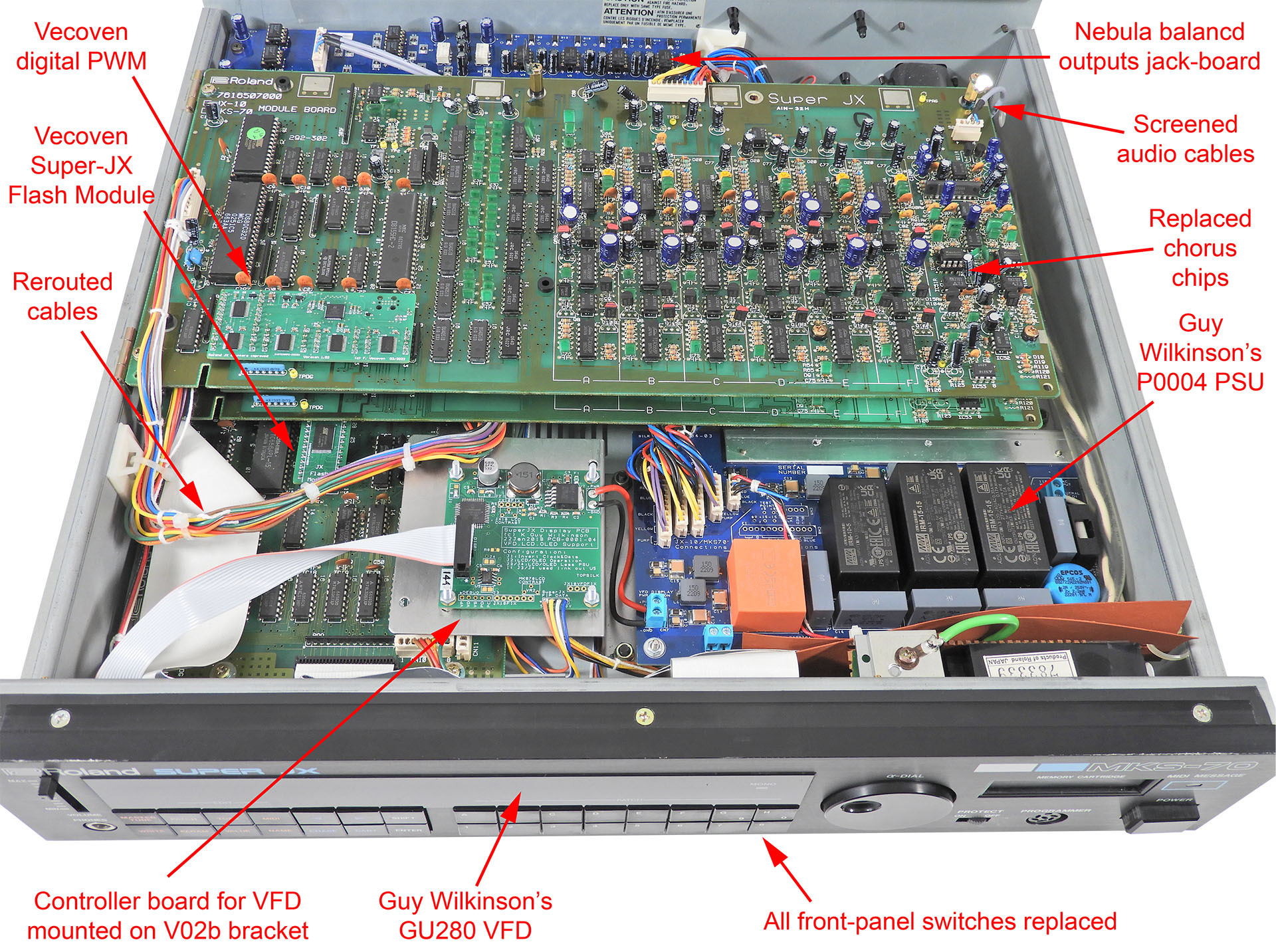
Brent had already bought some bits 'n' pieces and packaged with his MKS-70 were Fred Vecoven's Super-JX Flash module, Fred's latest digital PWM kit and four Xvive MN3009 replacement chorus chips.
Fred Vecoven's Super-JX Flash Module is part of my Roland MKS-70 full upgrade package.
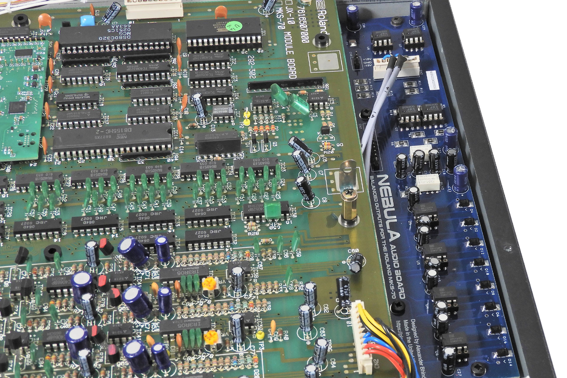
Knowing that this Roland MKS-70 full upgrade was coming in, I bought a GU-280 VFD replacement display kit off my friend, Guy Wilkinson and had ordered parts to build a Nebula balanced outputs jack-board and a P0004 modular switched-mode power supply. Is there a Super-JX (MKS-70 or JX-10) on the planet that's not powered by a P0004?!?!?
Delivering superior phase coherency, Nebula uses dedicated balanced line driver ICs to produce balanced outputs of each channel, as opposed to a dual op-amp configuration. Each output line on Nebula has a full compliment of diode protection and inductive and capacitive filtering which considerably improves the signal quality. Nebula is also now available with optional screened internal audio cables which reduce the noise picked up from within the MKS-70.
Brent figured that while the machine was here, it would be prudent to also change the front panel switches... so I ordered them, too.
Okay, so Brent told me that his MKS-70 was displaying random behaviour like freezing, intermittent booting, bad sound and so on. I immediately suspected the power supply so when I got, I was NOT going to switch it on!
Instead, I ripped out the power supply as a P0004 modular switched-mode power supply was already on the upgrade list.
I could immediately tell the power supply was quite fatigued. The filtering capacitors were starting to swell and there was some mild scorching around the rectifier joints.
Then, on removing the power supply, I was shocked to find that the 2SD1406 responsible for regulating -15V was so dry-jointed, that none of its pins were making contact with the tracks on the underside of the PCB.
Here's the underside of the power supply PCB showing Q4 (a 2SD1406, highlighted in red ) which is part of the -15V regulator circuit. As you can see, it's had enough! Dry-joints are a common source of problems on these old PCBs, especially under components that get hot.
This Roland MKS-70 full upgrade isn't cheap but if you're a Super-JX owner, please at least consider replacing your synth's power supply with a P0004.
Having the right equipment and using a couple of very well seasoned techniques (which might not be in the book, incidentally), I'm able to remove components without marking, let alone damaging the PCB or the components themselves.
This is one of Brent's MKS-70 module-boards which is being prep'd for Fred Vecoven's digital PWM upgrade.
As original components for this generation of electronics are becoming scarce and increasingly more difficult to procure, with the customer's approval, salvaging them off jobs like this is a godsend and will inevitably help another Roland MKS-70 owner some time down the line. It's a true privilege being part of this kind of community! 😀
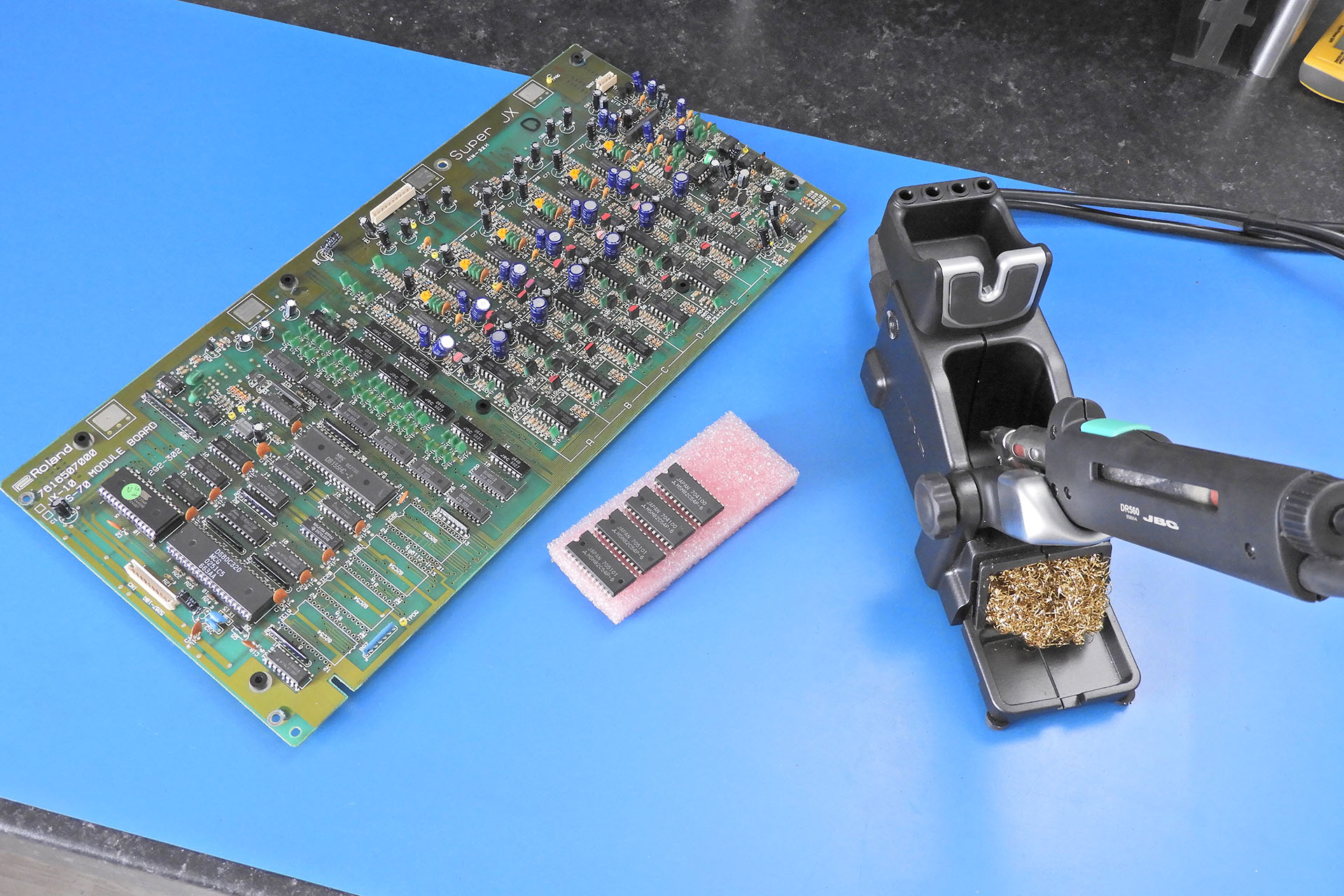
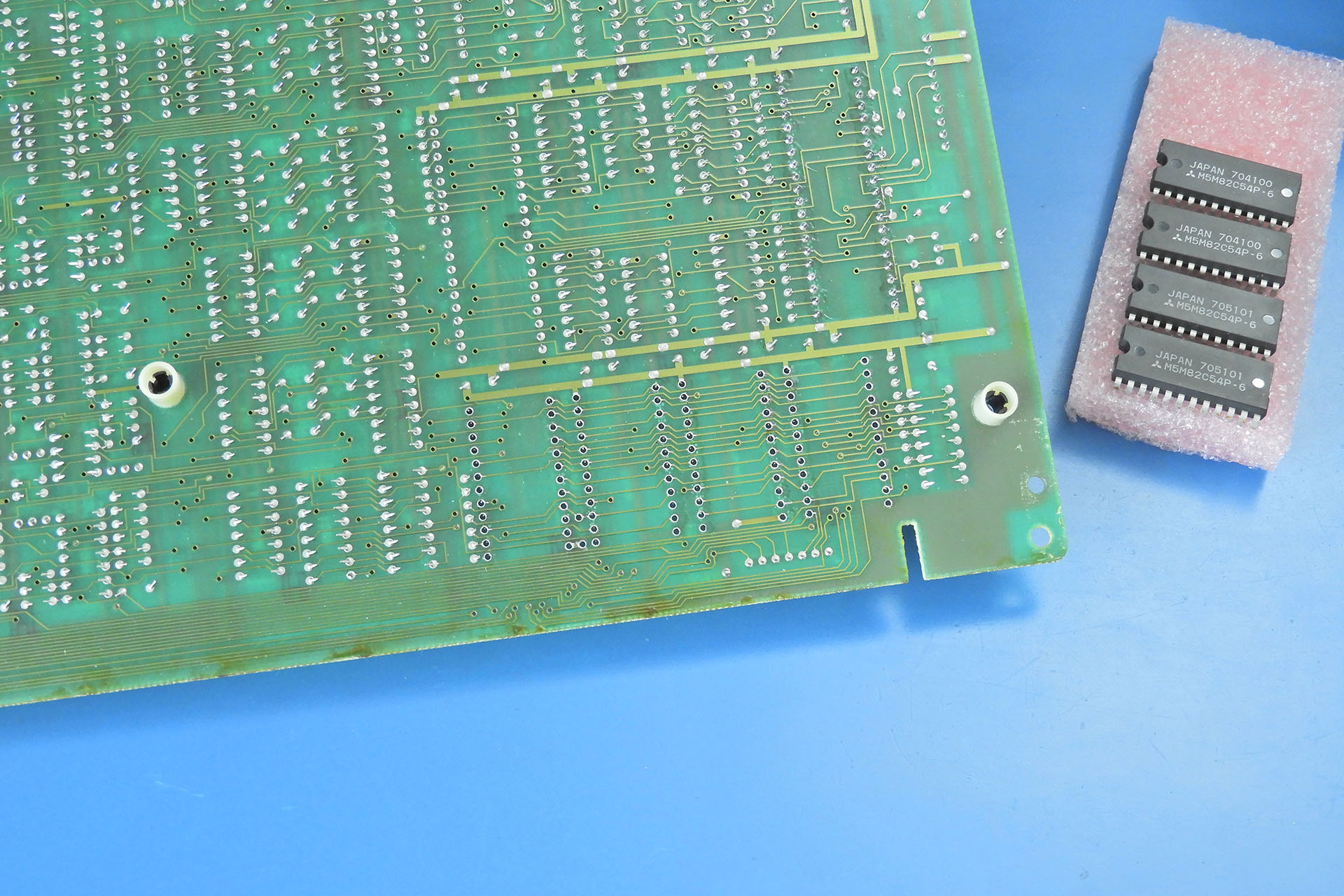
Here's the underside of the PCB after the four 82C54Ps have been taken off. You simply can't achieve this level of clean removal with a manual hand pump type desoldering tool.
Whenever I remove an IC, I always put a high-quality, turned-pin socket in its place, even when I install the Vecoven digital PWM daughterboards. Doing so makes life so much easier, should anything go wrong or in the case of the Vecoven PWM upgrade for the MKS-70, you just fancy going back (for some insane reason).
I always drop in some high-quality sockets prior to installing the Vecoven daughterboards.
!!! WARNING !!!
The expression “all the gear but no idea” might not be universally known but the sentiment probably is. Whilst there’s absolutely nothing wrong with having a confident character, doing your best at what you know and accepting the fact that you shouldn’t attempt the things that you don’t, may be considered a more valuable attribute. It’s called wisdom.
I periodically receive boards from people who for example, have watched a video on YouTube and decided that they can immediately do some in-depth work on a thirty-something year old synthesiser. Having the right equipment is only part of the story. Knowledge and experience take time and cannot be acquired over night let alone via a YouTube video.
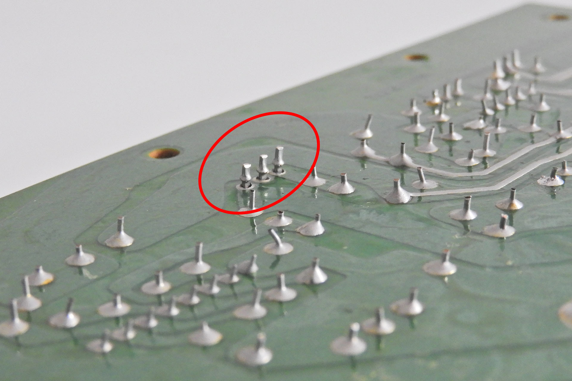
If you want to remove devices like the counters on the Super-JX voice-boards for example, PLEASE consider following these steps:
Using a pair of side cutters, snip the IC legs close to the body of the IC that you want to remove.
Then, using a soldering iron and a pair of tweezers, simply pull out the legs from the solder pads.
Once the pins are out, it’s much easier to remove the residual solder from the respective solder pins, with a good quality, electronic desoldering tool and you’re far less likely to damage your voice-boards.
I strongly recommend that you practice on some old, unwanted PCBs before you start working on your valuable Super-JX!
When removing components, a pair of side-cutters, a pair of tweezers, a good soldering iron, a reasonable desoldering tool and a lot of patience will do just fine.
Yeah okay, you lose the components but that’s a small price to pay against ruining your Super-JX voice-boards.
Okay so you lose your components but there's considerably less possibility of damaging your boards, using this method.
I make no apologies if that all sounds a bit harsh. It's far more upsetting for me to receive damaged voice-boards, I assure you!
Of course, after doing all of that, you gotta test it all but a Roland MKS-70 full upgrade is so worth it and gives this legendary synth module a whole new lease of life.
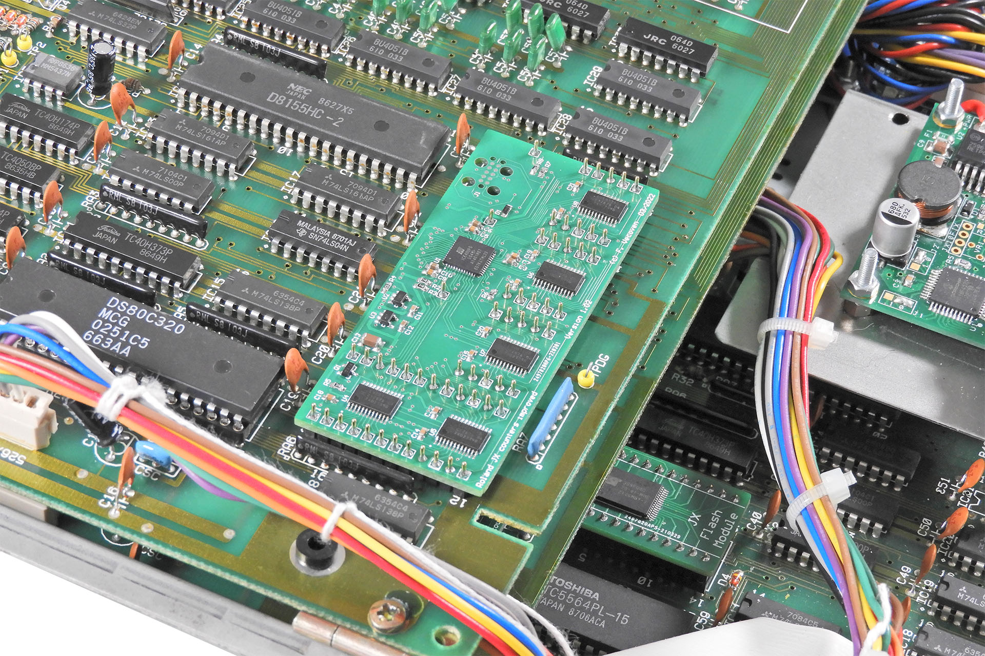
And here is one of the Vecoven digital PWM boards installed on to a module-board.
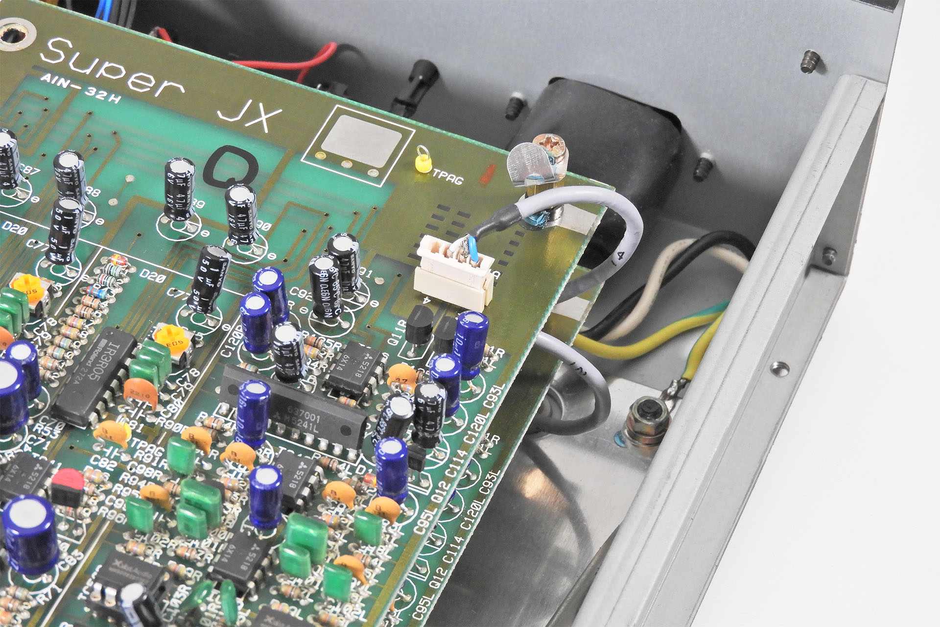
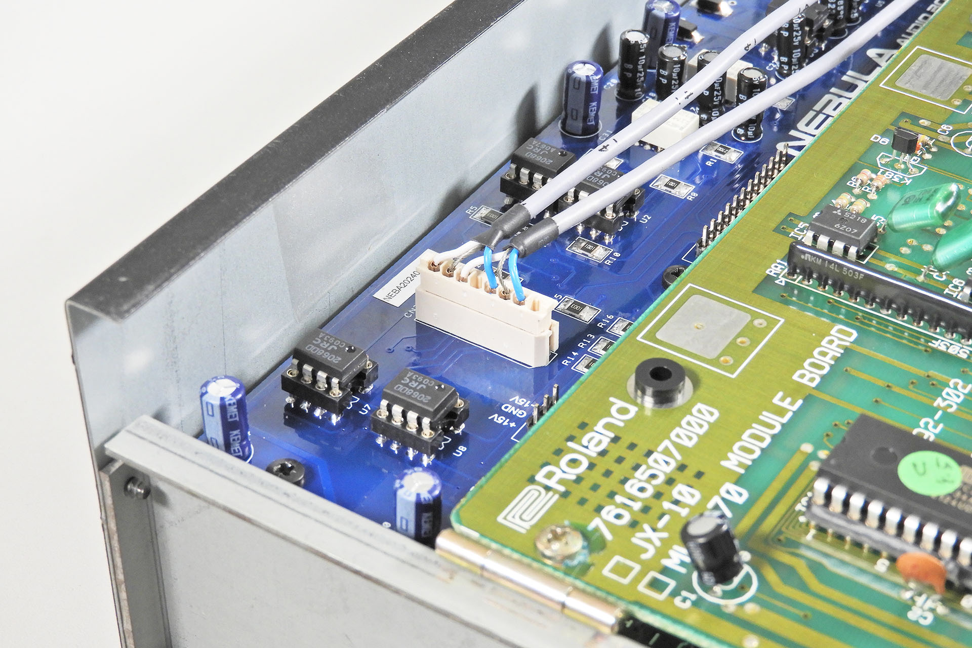
A few weeks ago, I decided to take an idea I've had for a long time, to the next level; I made a pair of screened audio cables for the Roland MKS-70 to replace the original 'wires' that connect the outputs from the module-boards to the jack-board.
Accepting the insane cost of the tool that crimps the wires to the terminals that are inside the Molex connector was the hard part! Also visible, is the insulating boot over the IEC C14 power connector and of course, the chassis is securely connected to mains earth.
Before I started work on The Miami Sound Machine and while everything was still factory, I used Brent's instrument to test my new screened audio cables. A plug 'n' play installation, this is a simple but very worthwhile upgrade. You can read the whole story here. 🙂 Indeed, Brent's instrument was the first to receive my new screened audio cables for the Roland MKS-70.
Here are my new screened cables for the Roland MKS-70, fitting snuggly to Nebula's audio board.
If you don't want to buy Nebula, then these screened cables will work equally well with the stock Roland jack-board.
Part of the work I do, includes keeping the customer updated on progress. I'm not sure what's happened in the past year or so but things have just got rather busy. Maintaining regular communications with customers however, remains paramount.
Okay, so you want to know just exactly what the customer got on this occasion. What does this Roland MKS-70 full upgrade include? Well, here ya' go:
Guy Wilkinson's P0004 power supply for Super-JX.
Earth bonding kit with IEC C14 power inlet connector.
Replacement of wires connecting module-boards to Nebula with screened audio cables.
Fred Vecoven's Super-JX Flash module.
Fred Vecoven’s digital PWM upgrade.
Live-forever battery mod.
Replacement of all front-panel switches.
Chorus chip replacement with 4 x Xvive MN3009.
Rerouting of internal cables to reduce noise.
RE-MKS-70 rack-ears.
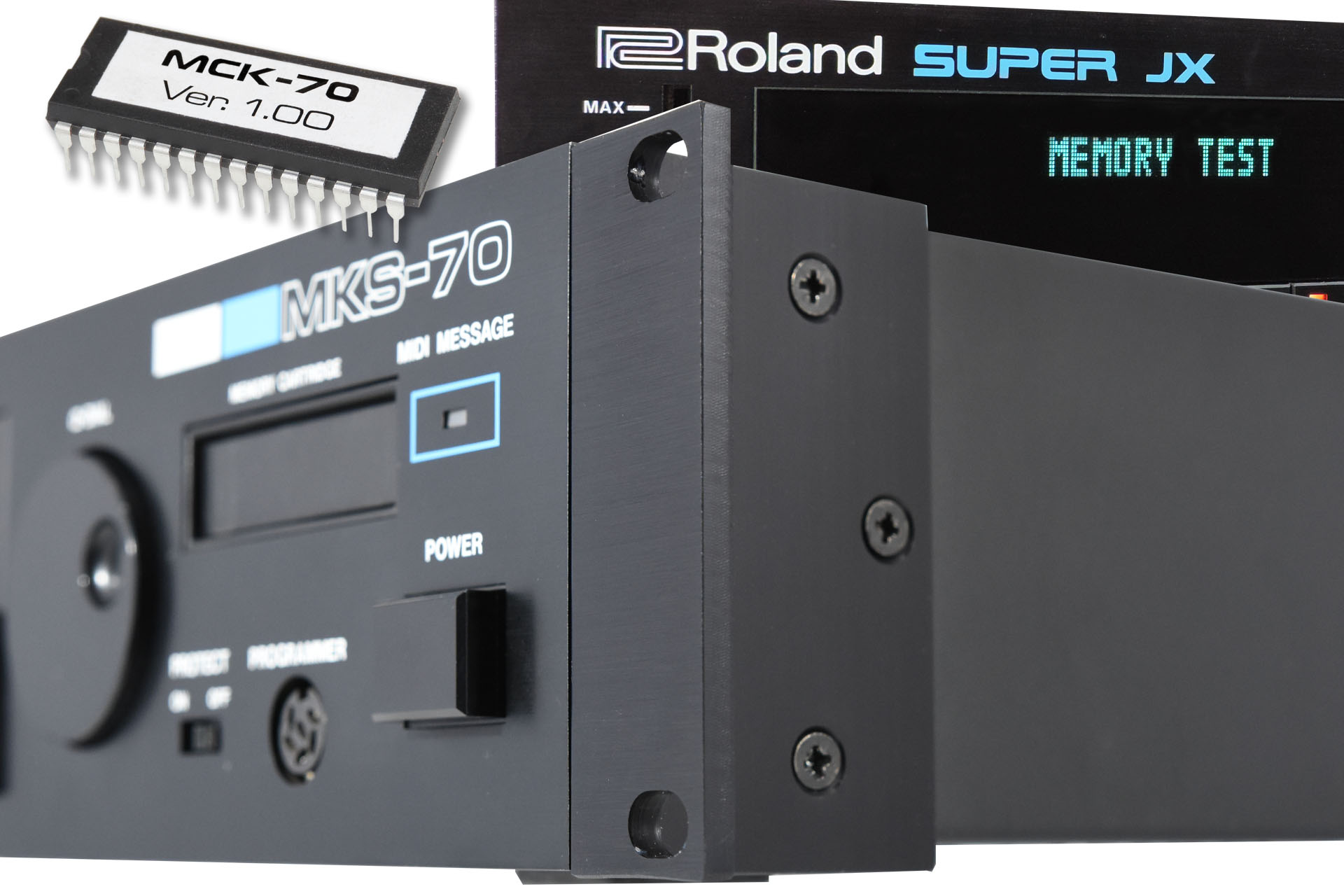
MCK-70 memory checker ROM.
Check all functions and calibrate module-boards.
15% discount over purchasing items individually.
Sub-assemblies like the P0004 power supply and Nebula are tested prior to installation. The MKS-70 is then tested after every single upgrade. If something isn't right, I'll know straight-away.
I've highlighted some of the options included in this Roland MKS-70 full upgrade. Note the severe lack of the original Roland cable looms!
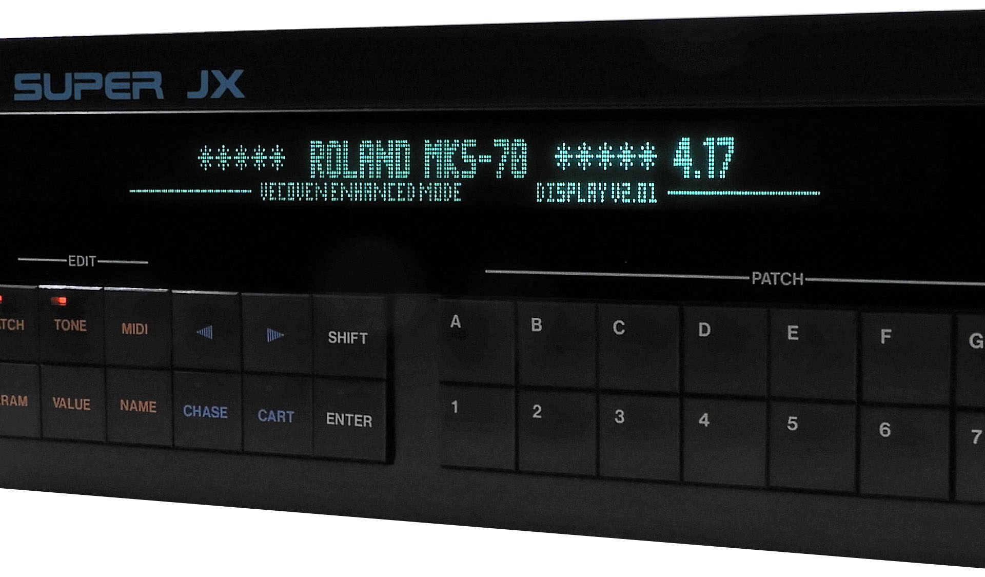
A lot of the upgrades are not apparent from the outside of the MKS-70 but Guy Wilkinson's GU280 based VFD definitely is and looks absolutely fabulous!
Visually one of the most impressive upgrades for the MKS-70, is Guy Wilkinson's VFD kit.
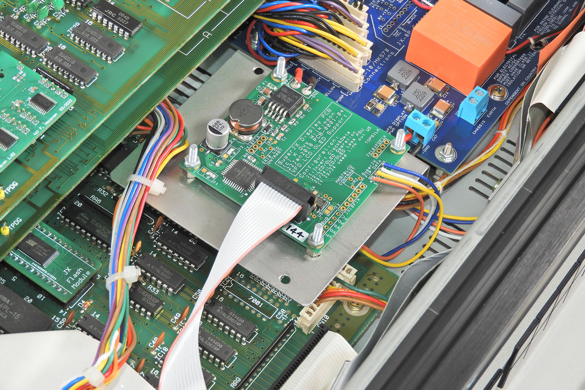
Making life a lot easier and in my humble opinion, being much more secure, the controller PCB for the VFD is mounted on my unique V02b bracket and not to the back of the front-panel chassis, as per Guy Wilkinson's installation instructions. Guy popped over while I was doing work on this baby and couldn't help notice the mounting solution. He loved it!
Guy Wilkinson's VFD controller PCB on my 1mm thick, mild steel, V02b bracket.
You may have noticed a couple of perhaps unexpected items in the inclusion list above. Well, Brent's MKS-70 didn't have rack-ears so he asked me to include my RE-MKS-70 rack-ear kit. He also asked for a copy of Guy's MCK-70 memory checker and so The Miami Sound Machine was accompanied by a few extra bits on its return to, well... Miami.
Included with the return shipping to the sunshine state, was my RE-MKS-70 rack-ears kit and a copy of Guy Wilkinson's MCK-70 memory checker.
A big T H A N K Y O U to Guy Wilkinson and Fred Vecoven for developing some awesome kit for the Roland Super-JX. 😀
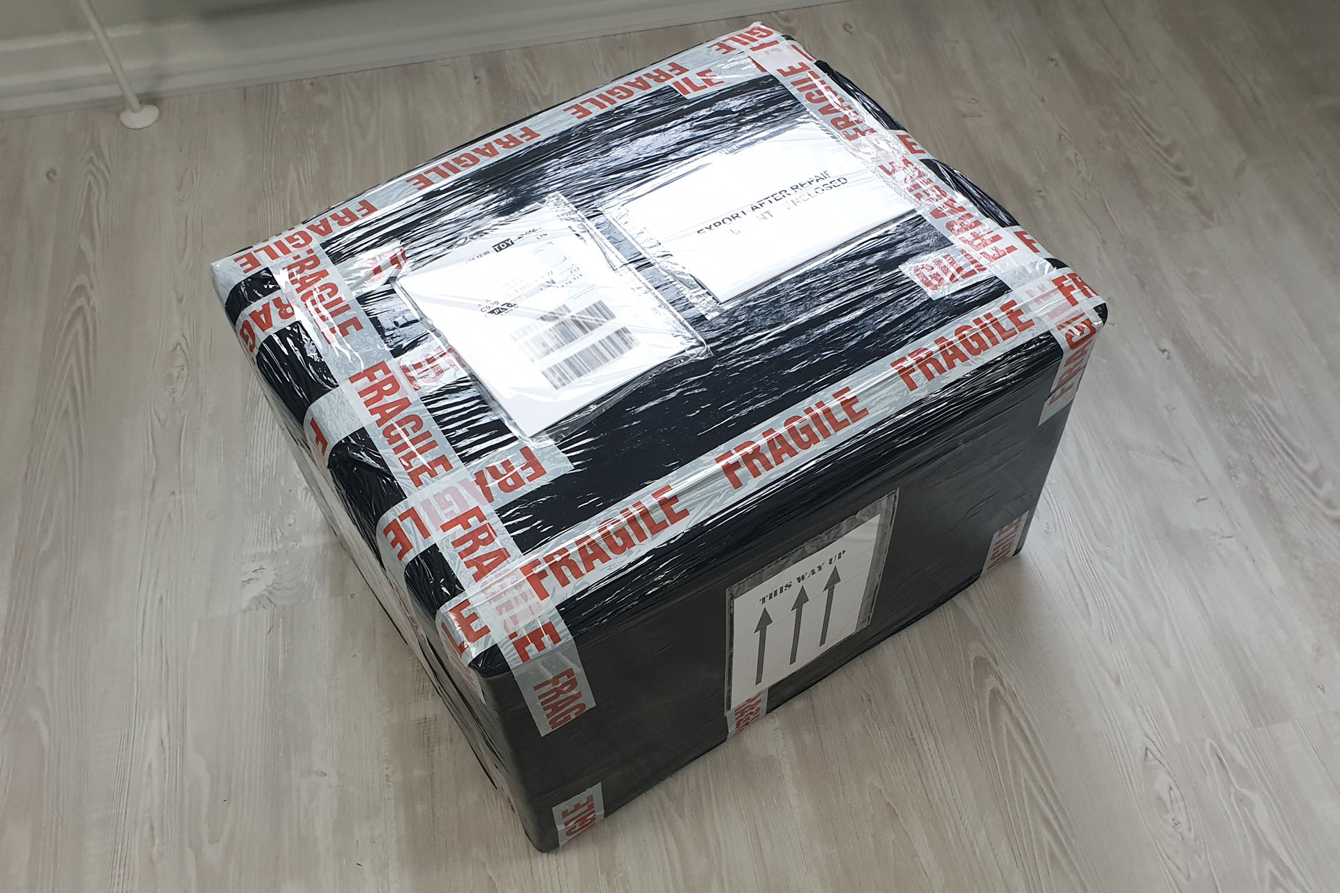
When it comes to packaging, I don't take any chances. Touch wood, I've never had anything damaged, let alone lost but I still believe in good, sometimes excessive packaging. Apart from protecting equipment, it helps the courier, too.
The Miami Sound Machine packed and ready to go home.
The shipment is marked up as 'Return after repair' so as to ensure that worst-case scenario, the customer will be charged on the cost of the repair and not the value of the item and the cost of the repair.
UPDATE - 10th April 2024
I'm always dead curious if and how much customers get charged import duty. It helps me advise future customers and is just really helpful for everyone. Brent kindly informed me of the following breakdown of duty charges:
MERCHANDISE PROCESSING 31.67 USD
IMPORT EXPORT DUTIES 167.78 USD
DUTY TAX PROCESSING 17.00 USD
TOTAL CHARGES 216.45 USD
Unfortunately on this occasion, US Customs got a bit funny and asked for 'additional information'. Annoyingly, the additional information was in fact included in amongst the documentation that accompanied the shipment but at stupid O'clock in the morning, I sent Brent everything that Customs had asked for, in a letterheaded document. A couple of days later, Brent received his baby.


 My town Hemel Hempstead, is twinned with Neu-Isenburg in Germany. In fact, I'm the chairman of the Town-Twinning Association here. Before Christmas last year, we were made aware of a European festival that was to be held in Neu-Isenburg and my family and I couldn't wait to go and meet up with some friends.