I regularly receive two questions from those interested in my PML-TX01. Both are about the Marshall JMP-1 input voltage selection:
Is the PML-TX01 replacement transformer for the Marshall JMP-1, 230V or 115V?
Are the voltage selector components diodes, ferrite beads or just fancy wire links?
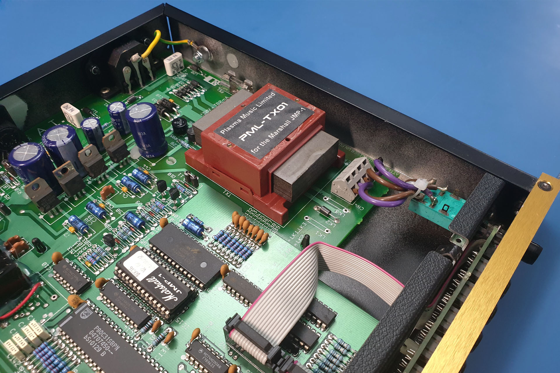
Here are the link locations to select the voltage rating of the primary windings for the transformer in a Marshall JMP-1. The example shown is set to 230V.
The answer to the first question is, just like the original TXMA-00014, my PML-TX01 has two separate primary windings, each rated at 115V. So…
EUOPEAN / UK VOLTAGE SELECTION. Wired in series, the primary becomes a single 230V winding which is suitable for 220V (Europe) and 240V (UK, Australia). To wire in series, connect ONLY LK2.
USA / CANADA / JAPAN VOLTAGE SELECTION. Wired in parallel, the primary becomes a single 115V winding suitable for 120V (USA and Canada), 100V (Japan). To wire in parallel, connect LK1 and LK3.
It's quite easy to implement 240V to 120V conversion, or 120V to 240V, for example. Those eighties style wire links can make things look complicated but the original links were JUST WIRE LINKS and nothing else, so you can use wire.
Looking from the pin side of the transformer, here are the voltage selection links and secondary transformer voltages. Apart from the higher quality material used for the laminates, the PML-TX01 is a direct drop-in replacement for the original Dagnall TXMA-00014.
It's important that the input voltage selection is chosen properly so below things are drawn that may be more representative of what you might actual see in your JMP-1.
Here's a diagram which resembles the actual physical layout of the power feed and primary voltage selection in the Marshall JMP-1.
SIDE NOTE
One might ask why the two individual primary windings are put in parallel for 115V. Why not just use one winding?
Well, a system uses a certain amount of power. Power is the product of voltage and current: P = V x I.
You can probably see now that if you half the voltage, you'll need twice the current to deliver the same amount of power. Placing the two primaries in parallel does just that, it doubles the current going into the system. 🙂
Check out my PML-TX01 low heat and low noise replacement transformer for the Marshall JMP-1 here.
And lastly...
! ! ! DON'T FORGET TO CHECK THE FUSE RATING ! ! !
So as I've just intermated, the power requirement of a machine is the same whatever the supply voltage. Since power = current x voltage, if you're halving the voltage, you'll be doubling the current.
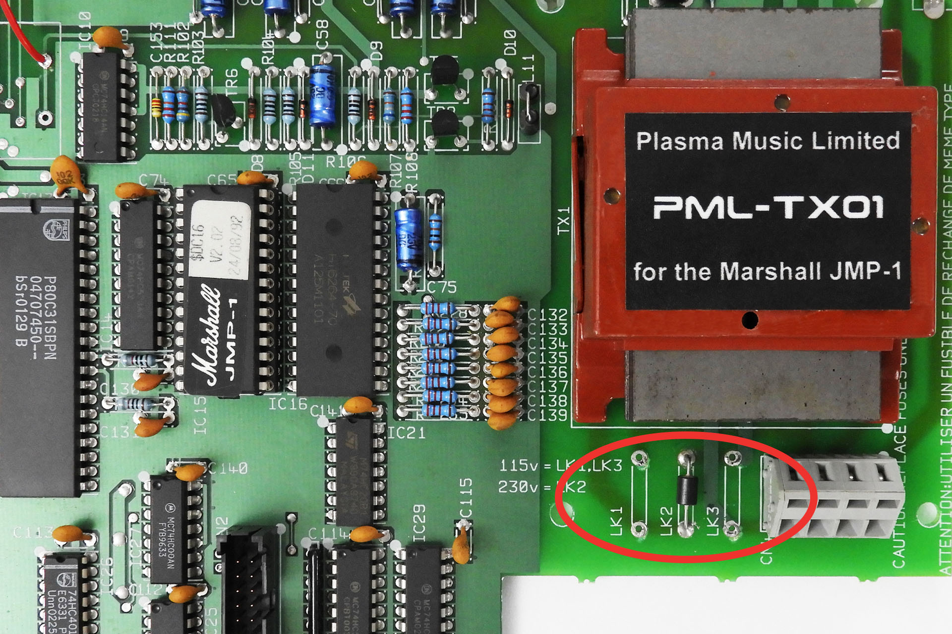
Don't forget to select the correct fuse rating for your region.
If running at 230V, the JMP-1 fuse should be 80mA (230V x 0.08A = 18.4W).
If running at 115V, the JMP-1 fuse should be 160mA (115V x 0.16A = 18.4W).
'T' stands for 'time delay' so use a time delay fuse.
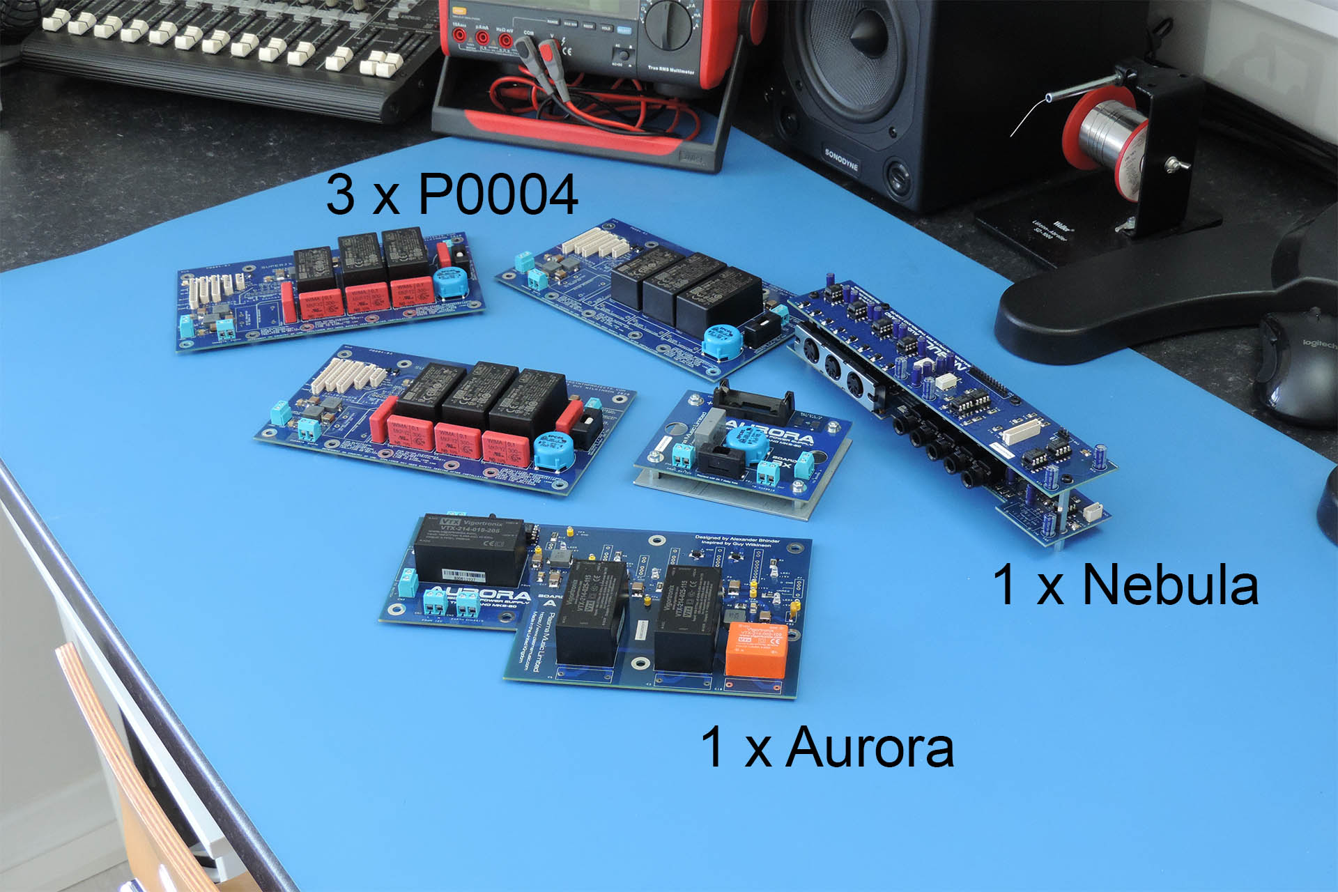
It’s amazingly reassuring that MKS-70 and MKS-80 owners are so interested in the stuff that Guy Wilkinson and I have designed and built. Indeed, it's been a busy few days.
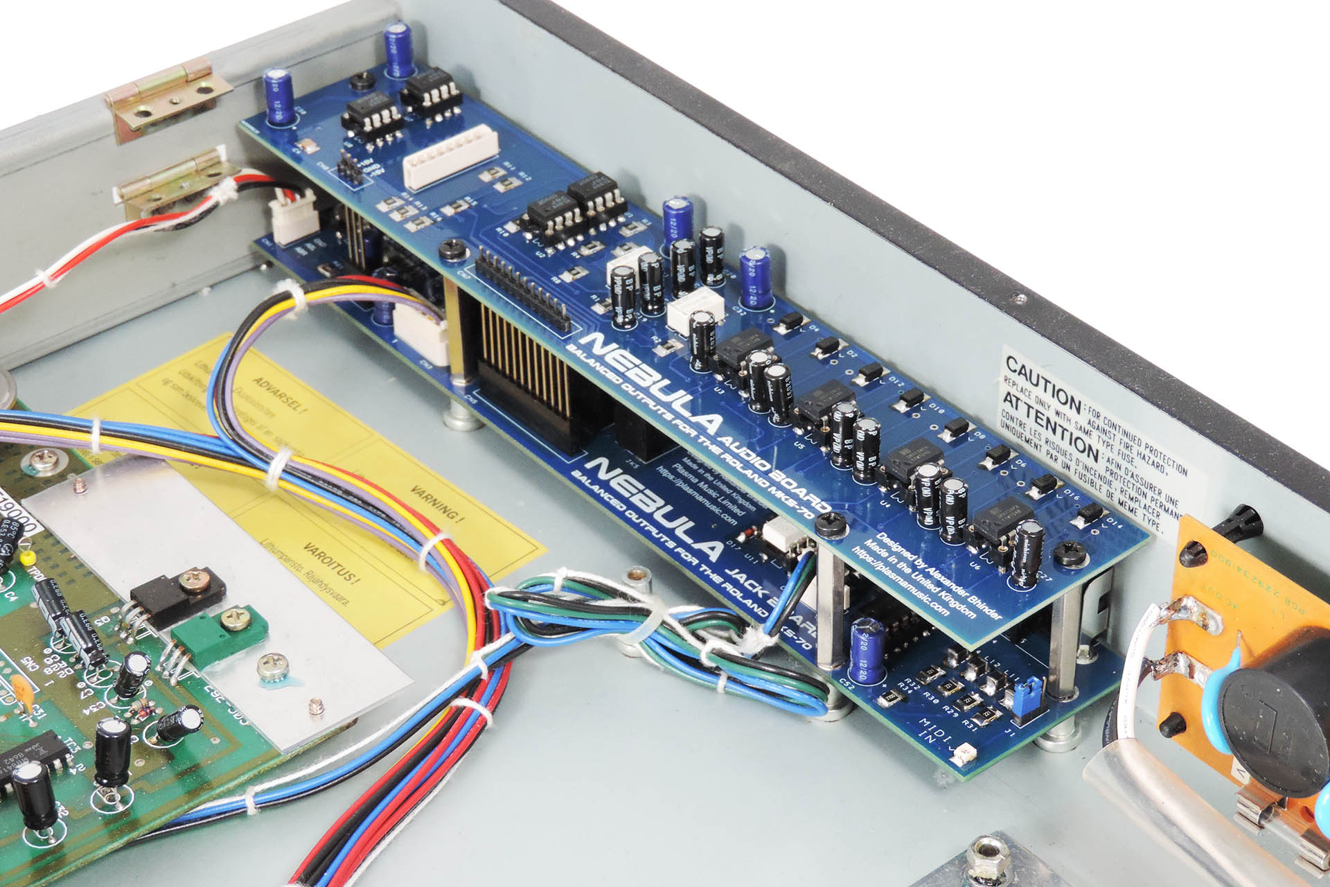
Pictured are three of Guy’s P0004 power supplies for the MKS-70, one of my Aurora power supplies for the MKS-80 and one of my Nebula output boards which gives the MKS-70 balanced outputs and upgraded MIDI hardware.
You may notice that there are a few components missing! Except for the nebula, the power supplies are currently unfinished!
It seems that it’s not just the likes of Mercedes Benz and Jaguar that are victims of the global component shortage. A few months ago, it was reported that Jaguar delivery times have increased by three or four months, due to issues precuring processors. Well, it seems that even passive components can be difficult to get hold of, at the moment.
The Y2 safety capacitors that I use on the power supplies have become really quite thin on the ground. When looking for alternatives to those originally specified, it’s not just the electrical characteristics that must match. The physical dimensions are also crucial as anything that’s a different size, would require a change of the board lay-out. Well, I’m pleased to tell people that they are finally on order, in stock and I’m expecting them any day. 😊
The keen-eyed will also notice a lack of one specific AC / DC converter. Well spotted! These are also on order and I’m hopeful that they’ll also be here shortly.
I still have a load of stuff to build for a MKS-70 that's just arrived from California and I'm in the middle of building and installing Fred Vecoven's PWM kit into another MKS-70.
I'm also arranging to meet a customer from Holland who's bringing over this slightly ill MKS-80.
Today I received the sad news that my old boss from my days at Roland (UK) Limited in the late eighties, had passed away.
A real character, kind, generous and trusting, Fred was quite simply, a lovely person. I only have fond memories of those magic days. Everyone who worked at Roland or was involved with the company, will have at least one hilarious story involving Mr. Fred Mead.
Here's what one of my old Roland colleagues Alan Greensall put up on Facebook:
Fred Mead, one of the key figures behind the establishment of Roland UK as perhaps the most dynamic British MI company of the 1980s, has died just five days short of his 81st birthday, following a long illness.
Though destined to become Roland UK's sales director and buyer, Fred Mead originally trained as an engineer and cut his MI teeth working for Tom Jennings' Vox company, in Kent. Later, he went on to become buyer and then factory manager for Dallas Arbiter, then one of the largest companies in the industry. It was at Dallas Arbiter that Mead was to meet Brian Nunney, the firm's export director.
Following the collapse of Dallas Arbiter in 1974, Nunney was approached by the Danish Roland and Hammond distributor, Brodr-Jorgensen to start a UK division, a challenge he readily accepted. Looking for people with MI experience to help get the fledgling business off the ground, Nunney turned to Fred Mead, as he recalls:
"The man who had been most helpful and supportive to me in the Dallas organisation was the factory manager, Fred Mead, so I rang Fred and we met - on two adjoining deckchairs in Hyde Park, of all places."
Though, by his own admission never having sold anything in his life, Fred was immediately given the entire South of England to handle and was summarily "thrown in at the deep end" as he later recalled.
"I’d never sold before and I was terrified, but in February 1975 we started the company. After a week or two, Brian finally said it was time for me to go out and sell and that the first person he wanted me to go and see was Lou Dean, who ran an organ shop in Hammersmith. So I went down, looked in this enormous shop, terrified by what I had to do. I think I smoked about six cigarettes, while walking up and down outside the shop and in the end I plucked-up the courage to go in. There was dear old Lou behind the counter with a great big cigar in his mouth. I took him through the products we had, the SH 3A, the SH1000, some Boss pedals and rhythm boxes and he looked at me and started to laugh."
I asked him why and he said:
"I’ve been sitting here watching you walk up and down outside the shop all this time. How many cigarettes have you smoked?"
Then he said:
"Get you order pad out. I’ll tell you now, Brian Nunney had already told me you were on your way down here, so I was looking out for you."
Fred continues...
"We developed the company quite well until 1980, when Jorgensen in Denmark went into receivership. But despite the problems in Denmark, we were flying in the UK so, in effect, we took the company over on 9th January 1981 and created Roland UK, which was a 50/50 venture between Brian, Ken Stoddart, financial director, and myself on the one hand and Roland, Japan."
Based in what had previously been the Smiths Crisps factory in Brentford, west London, Mead and Nunney formed a tightly knit team, which was to become one of the most potent in the industry. Key figures in the Roland UK of that era included Dave Marshall (today managing director at Sound Technology), Alan Greensall (later at Sound Technology and then Line 6 before forming his own Synergy Distribution), Chas Smith (who went on to run Avid in the USA) and Jed Allen, later with DiGiDesign.
"I was very pleased to have Fred on board." Brian Nunney recalls.
"I could not have operated without him and we did everything together. If I went to Japan, which I did once a year, Fred came with me and likewise we went to Frankfurt, which everybody in the industry did every year. It would take a book to cover the adventures we had!" he laughs.
Sadly, Roland UK was destined to run into trouble, following the company's move to custom-built premises in Fleet, Hampshire in 1991 and a controversial expansion into warehousing and office facilities in Swansea.
"In my opinion it was a very bad move." Fred later recalled.
"The logistics were bad and we over-stretched ourselves financially by doing it - well, not only by doing that, but by building Fleet as well. All this strain on the company’s finances coincided with a change in the economic climate of the whole country. Doing the Swansea thing altered all our lives completely. It was a mistake. I think that if we hadn’t moved there, we would have survived the financial turmoil of the company at the time. We had already been through one downturn in the economy without even noticing it, because our overheads were low at that time. But as soon as we did the Fleet/Swansea exercise, we reversed the situation."
Fred Mead retired from Roland UK in 1996, following Brian Nunney's retirement but the relationship endured. Nunney, following a battle with cancer, retired to the South of France and says:
"Fred and I remained firm friends and he visited me once a year for the last 25 years. Fred was the only one who visited me when I was in hospital following my cancer operation. I woke up and there he was sitting in an armchair in the room, completely unannounced, waiting for me to wake up, which was a really nice gesture and typical of Fred."
Fred Mead was predeceased by his wife Jean, and is survived by two sons, Richard and Gary.
Today I've been working on the new place and have been thinking a lot about Fred, the wonderful time I had at Roland and all the fantastic people I have been privileged to know, many of which I'm pleased to say, are still friends today.
Reflecting, I'm quite spooked at the crossroads I now see in my past. The choices I and perhaps others made for me, have all contributed to who and what I am today and the people I know now and those who I have known. Going to that interview with Fred, being offered the post of Group Technical Manager UK by him and accepting it, were three of those crossroads.
My time at Roland was exciting, even magical and will never be repeated.
In between repairs and fulfilling orders for peripherals for vintage gear, I’m frantically working to get the downstairs of Plasma’s new premises finished as I have a load of office furniture arriving at the end of the month. Eeek!!!
If that's not enough to keep me busy, I’m also building a couple of rack systems to go into the studio upstairs.
I REALLY don’t like DIY but as I’ve said before, sometimes there’s no choice. You just gotta do it!
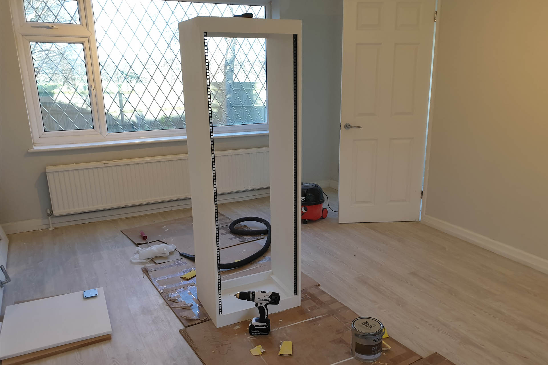
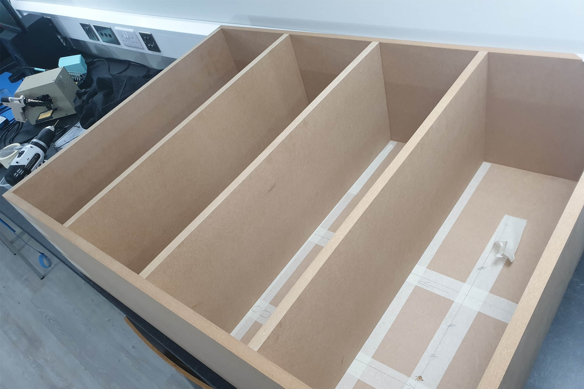
This 33U rack enclosure will be home to my guitar and bass processors. Yep, after many, many years, I’m ditching my trusted EMS rack cases and wanted my new rack enclosures to fit in more with the décor of the new place.
Making what is essentially a box, isn’t particularly difficult. It’s the finish that makes the real difference. Today I fitted the front and rear (not shown) rack rails, just to line them up. They’ll come off shortly, so that I can start applying top coat.
I also have to make the base-board. At 1.5m high, 400mm deep and standing as is, this enclosure would be quite unstable, so I’ve made a base using 18mm plywood, which extends beyond the front and rear of the unit and which will be fitted with castors.
Here you can see that I've applied primer and temporarily fitted the front rack rails. In the lower left corner, you can see the plywood base board which is ready to be drilled for castors.
As a songwriter / producer, I never thought I’d be doing this kind of work! In some ways, it’s been quite therapeutic and I’ve been forced to apply a patience I never knew I had, LOL. 😀
As mentioned, I'm busy trying to get all the stuff done in what's now the kitchenette and office area.
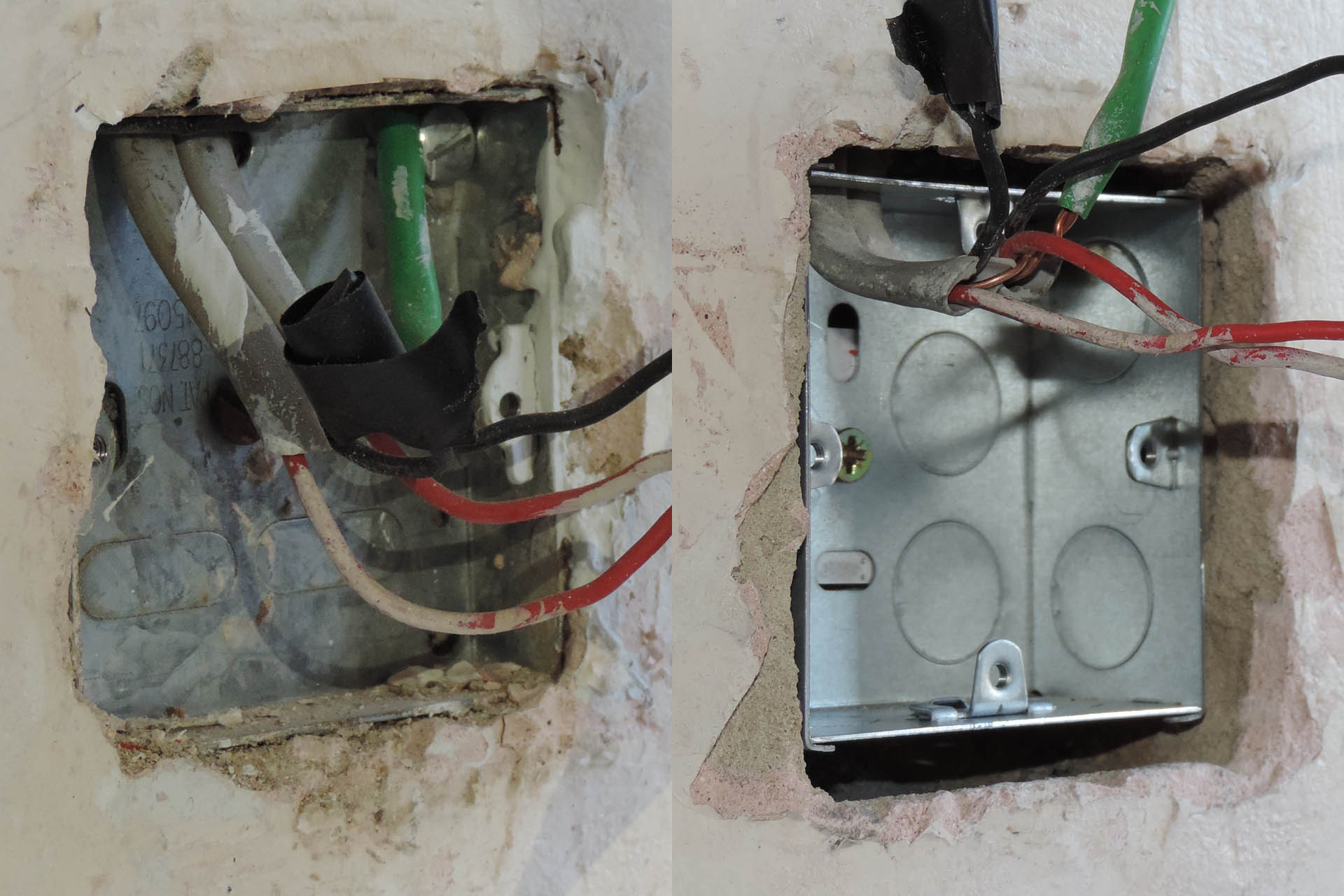
While the boys from Bonell Property Renovation Limited really accelerated things, there's still a lot of work to do. One really annoying job, is smashing out the light switch backbox cavities which are only like 10mm deep or rather an imperial version of that, going by the age of the house. The new switches are very modern and stylish but require a (standard) 25mm. I figured while I'm doing this, I might as well get as much space as I can for potential smart switches which might be installed at a later date and so I bought 35mm backboxes.
On the left is the original 10mm backbox and on the right is a newer 35mm backbox.
Bashing out the backbox cavities in breeze block walls isn't particularly difficult but it's really messy. Stuff goes everywhere and the process generates a lot of dust.
A messy job!
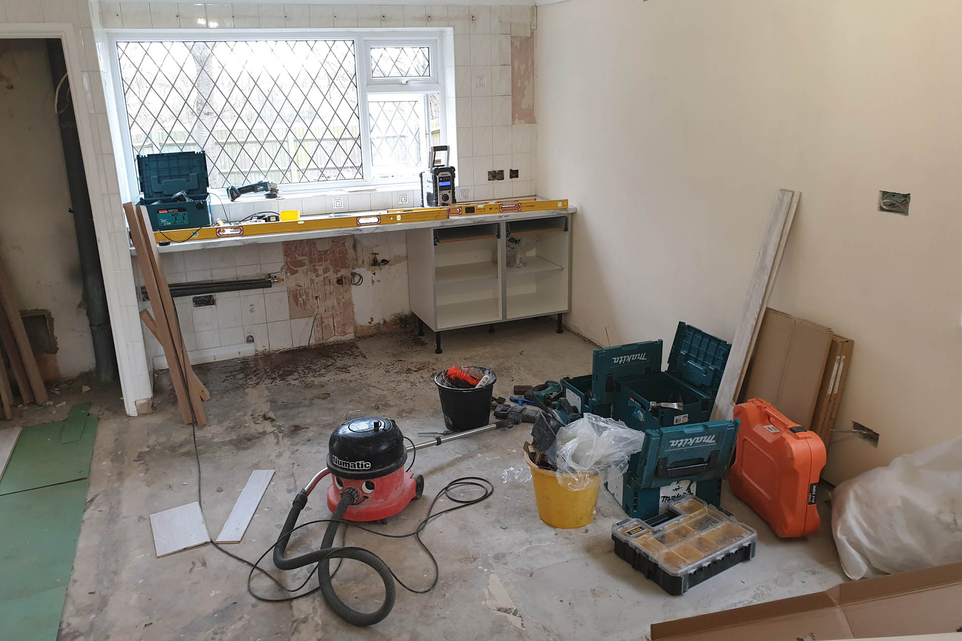
This space I'm working on, was originally the kitchen and dining area and when I moved in, I immediately ripped out the old kitchen intending to install a kitchenette. I don't need an oven, hob or a large amount of worktop and on top of that. Instead, I wanted as much space as possible, for the office, which I figured would occupy the old dining area.
All this space had been badly papered with cheap lining paper and a few weeks ago, Julie my wife and Tsunami my youngest daughter, stripped it for me. Painted over many times, while the paper had started to lift in several places, in other places, it seemed like it had been stuck on with superglue! 🙁 As the paper came off, it became clear just why this part of the house had been papered in the first place; the walls were just bloody awful with bad filling and many damaged areas. There's an archway which now looked like it was added long after the house had been built and the installation although solid, hadn't been finished properly. The concrete around the structure hadn't been smoothed out to the surface of the original walls. What a mess!
I need to get this space sorted as soon as possible but the prospect of filling and sanding the walls and generally making good of such a large space was daunting, to say the least but eventually I started... just a week ago.
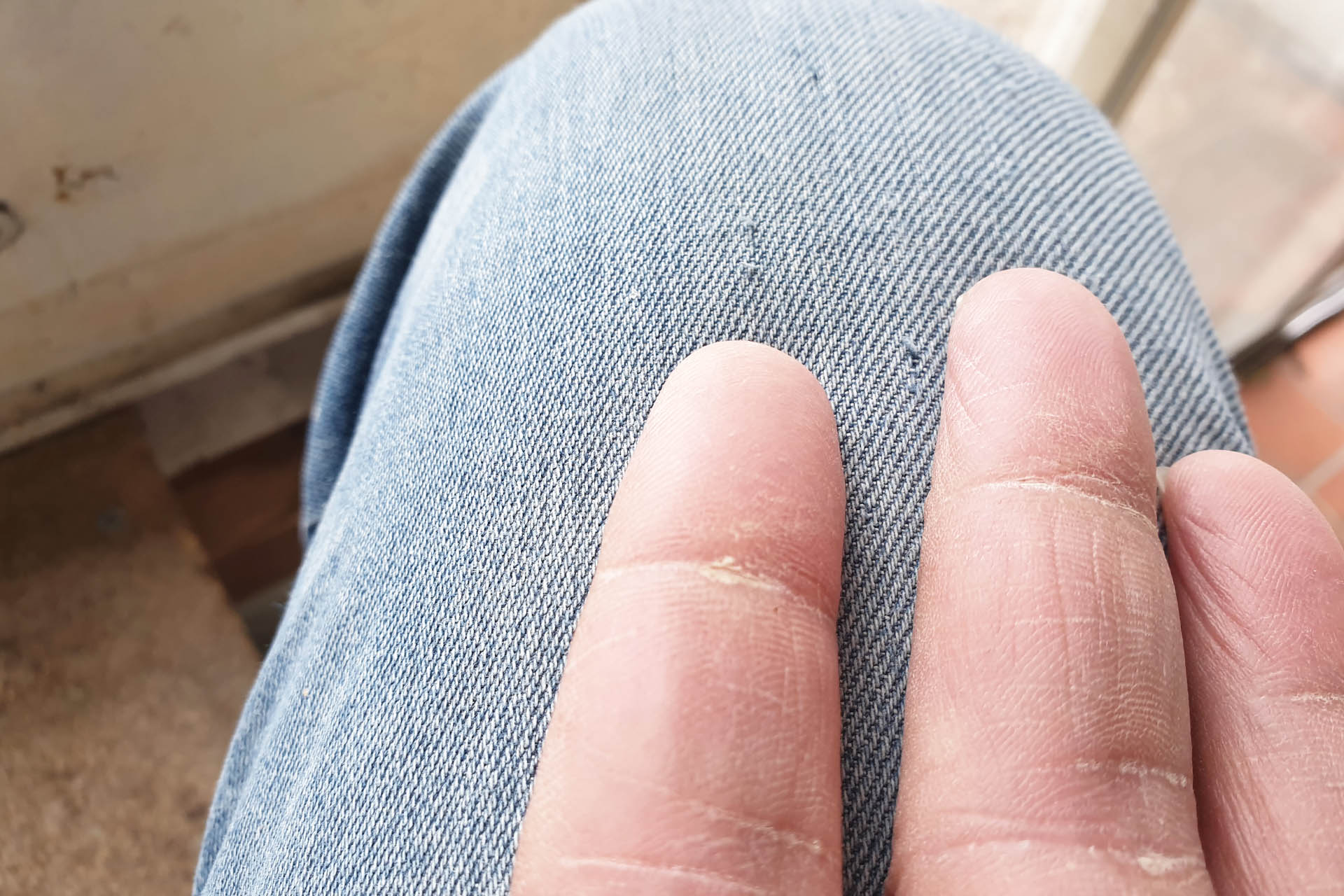
After the first day, my hands were really sore and after the second day, I couldn't access my mobile phone. After cleaning the fingerprint scanner, rebooting and looking for solutions on line, I discovered that my fingerprints had disappeared! WTF?!?!? Seriously?
UPDATE - 15th January 2022
Today things are finally ready for the top coat! Rolling the walls is boring but easy. In my opinion, the end result however, is determined by the quality of the cutting-in and I'm going to take my time doing this.
Hmm... perhaps it's easier just to buy a grey shirt!
It's been five months since I began work on what's going to be Plasma Music's new home. Not as big as what I had before but a reasonably sized detached property and just down the road, it's going to be an awesome base for my creativity and from which to run my technical services.
Redecorating upstairs is done and I'm now moving equipment in. I've still got a way to go before the studio is operational, like I'm designing some rack cabinets and waiting for others to arrive and of course, the cabling. 🙁
Downstairs, the lounge is waiting to be painted and the lab is not just done but totally up and running, making work soooo much easier.
I eventually decided to get in some professional help to finish off the kitchen, what's going to be the office and the hallway. My friend Adam, put me in touch with David of Bonell Property Renovation Limited. I sent David an illustrated brief of what was required. Matthew his carpenter popped around a couple of days later, to check some details and take some more pictures. A favourable quote soon arrived in my inbox. I paid a deposit and at 8:00 this morning, a bunch of lads turned up to begin work.
The boys had only been here a couple of hours and already things are starting to take shape.
Tidy, efficient, polite, considerate and really fast, I popped over a couple of hours later, just to check on progress and see if they needed anything. Well, I was gobsmacked at what had been done, just in that space of time. I think these guys are going to get five stars from me! 😀
A great bunch of lads caught chilling out, on their well deserved lunch break.
Things are finally starting to take shape. I can see light at the end of the tunnel and I'm really very excited, now.
UPDATE - 14th December 2021
I popped down to drop off some components that arrived for a couple of builds and was blown away with the progress, just twenty-four hours later.
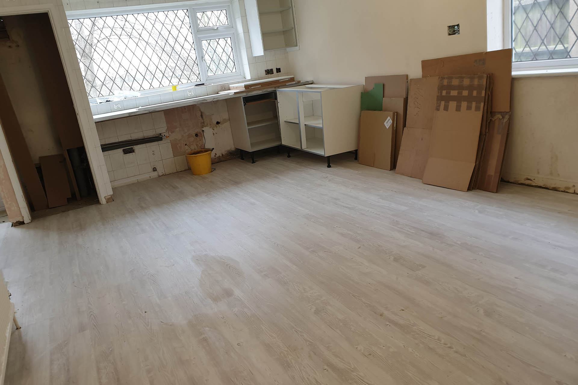
Twenty-four hours later and the flooring is down in the kitchen area, office and hallway. Seriously?!?!?
Forget the five stars, I'm just totally impressed!
There were two areas in the porch where plastering had come away from the wall. It wasn't too bad, to be honest but while I had a professional team in, I thought I'd put it on the list. That's also all sorted, now.
UPDATE - 23rd December 2021
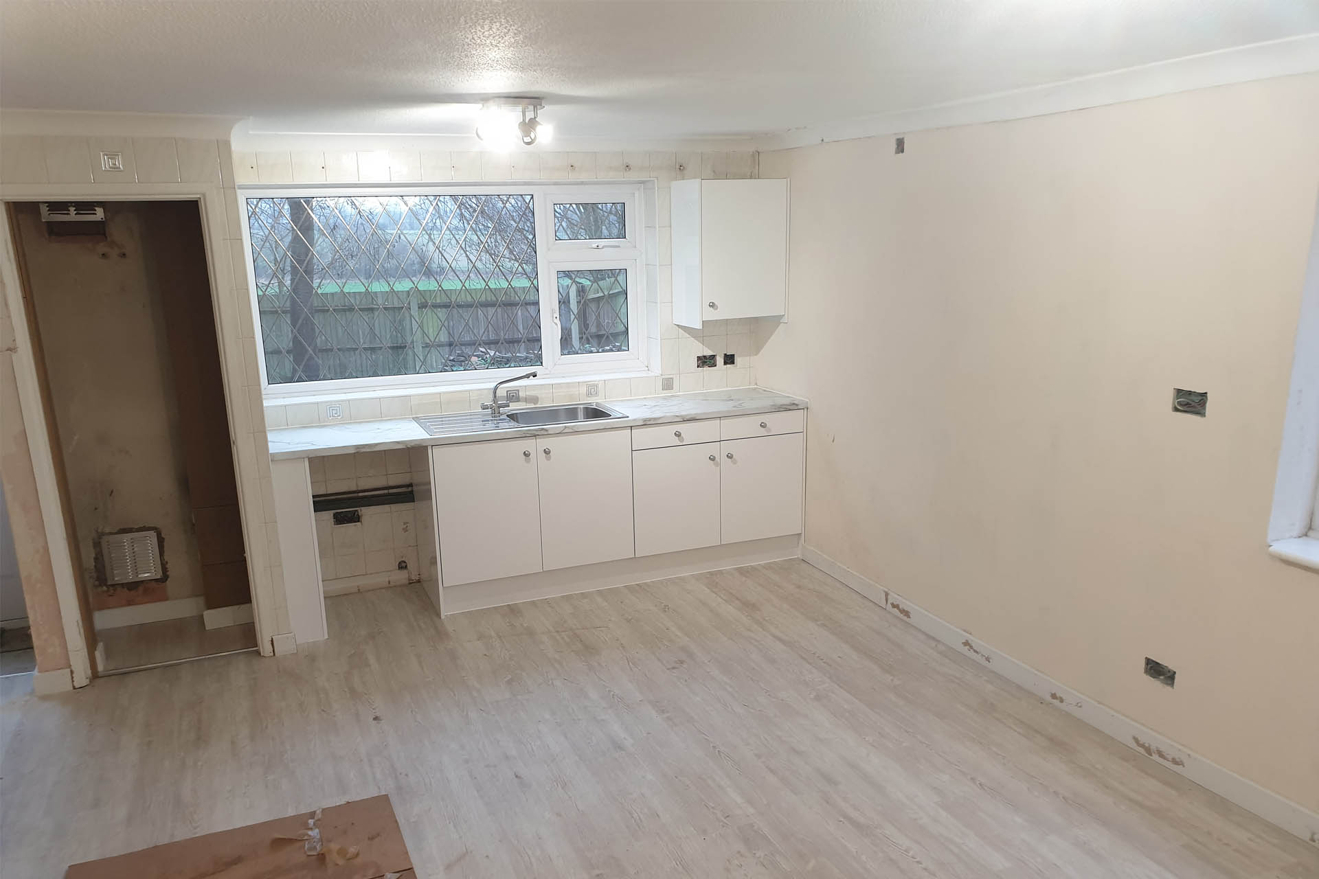
In just ten days, the boys had finished all the jobs that were on my list. What a transformation! 😀
I agreed with the builder, that I would do all the decorating. I therefore asked the lads, not to put the doors back, as I'll be re-painting them.
The wall opposite that in the picture above (which was re-plastered), isn't very smooth. The whole of this section of the house was papered with thick lining paper which my wife Julie and my daughter Tsunami, removed. I'll have to go over all the walls, filling and sanding, prior to painting. I only have four weeks to finish the whole lot, before the furniture arrives. 🙁
UPDATE - 26th January 2022
Bonell Property Renovation Limited is busy! That's because they're good! 🙂 so I didn't mind them coming back a couple of weeks later, to tidy up a couple of things.
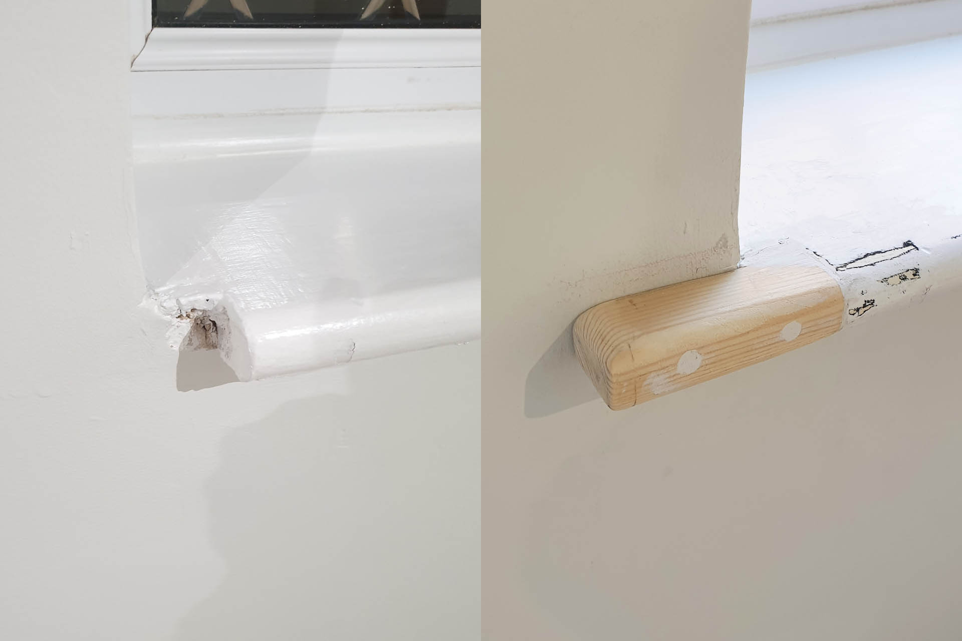
Pictured below is an example of two things; attention to detail and their fantastic level of craftsmanship.
A before and after of a window sill repair. Amazing work, Josh!
The original kitchen had a worktop bar thing and instead of placing it two inches away from the window sill, the original fitters cut the bloody window sill to make it all fit. WTH????!?!? This morning, Josh did an awesome Job fixing this. I hope I can do him justice with my decorating! 🙁
I’m not good at it and I absolutely hate DIY! On the other hand, there are occasions when you just have to do it.
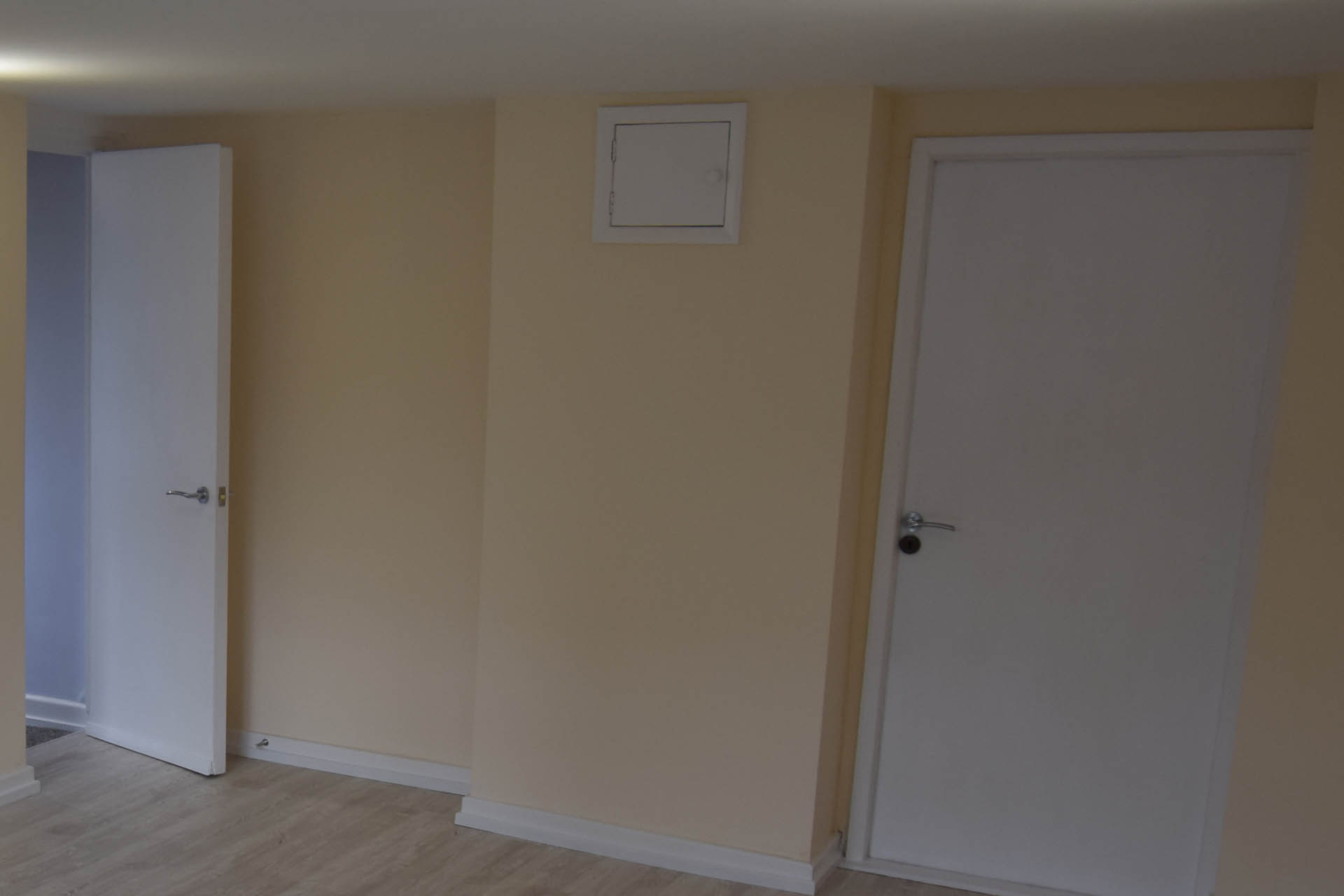
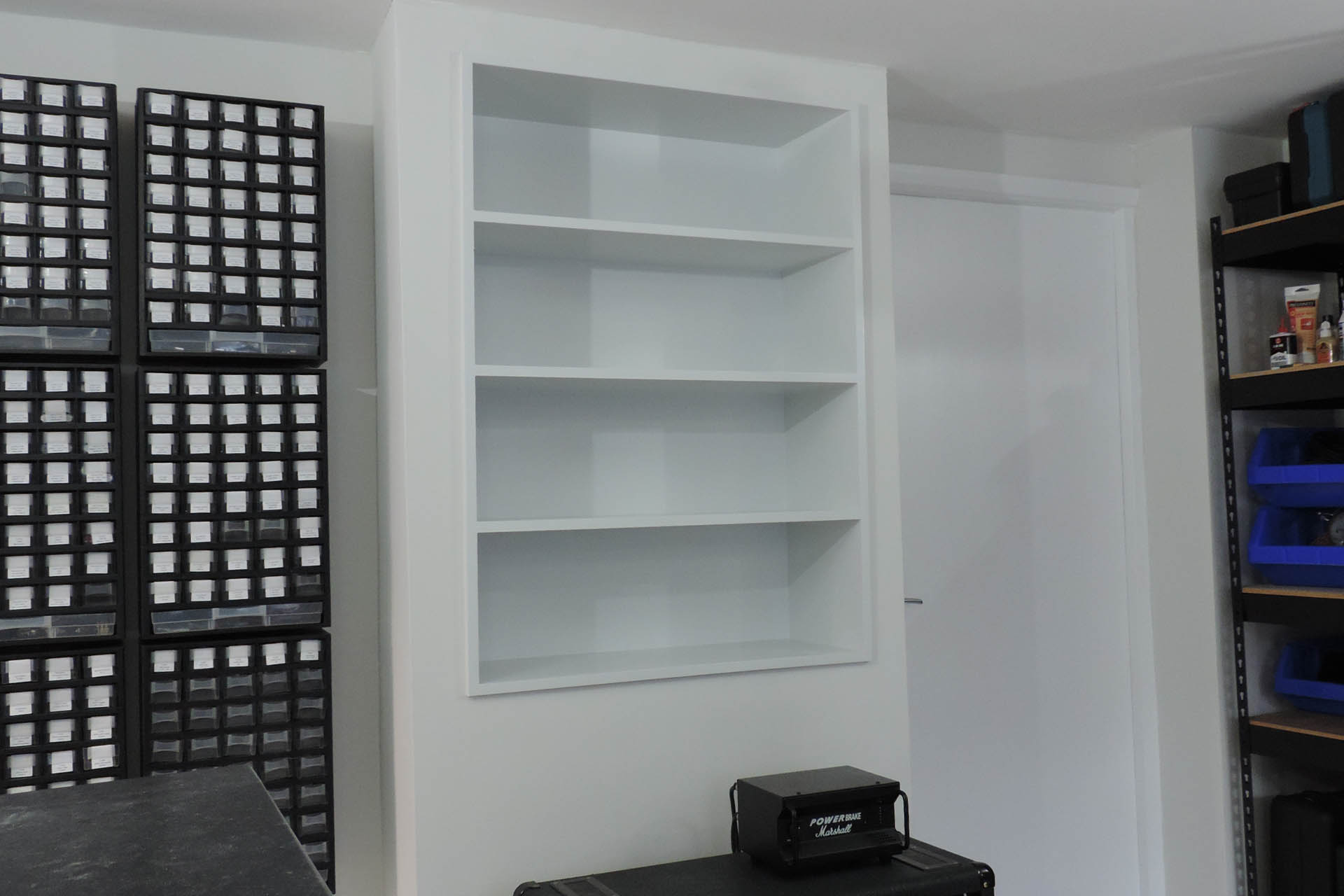
The lab at the new place has been built into the downstairs bedroom which used to be a garage. In 2018, the gas meter was moved, leaving a little hatch in a section of ‘boxed in’ nothingness.
This perspective of the downstairs bedroom, taken from a picture after I redecorated in 2017, shows the boxing around gas supply and pipes. The hatch provided access to the original gas meter which was ripped out a long time ago.
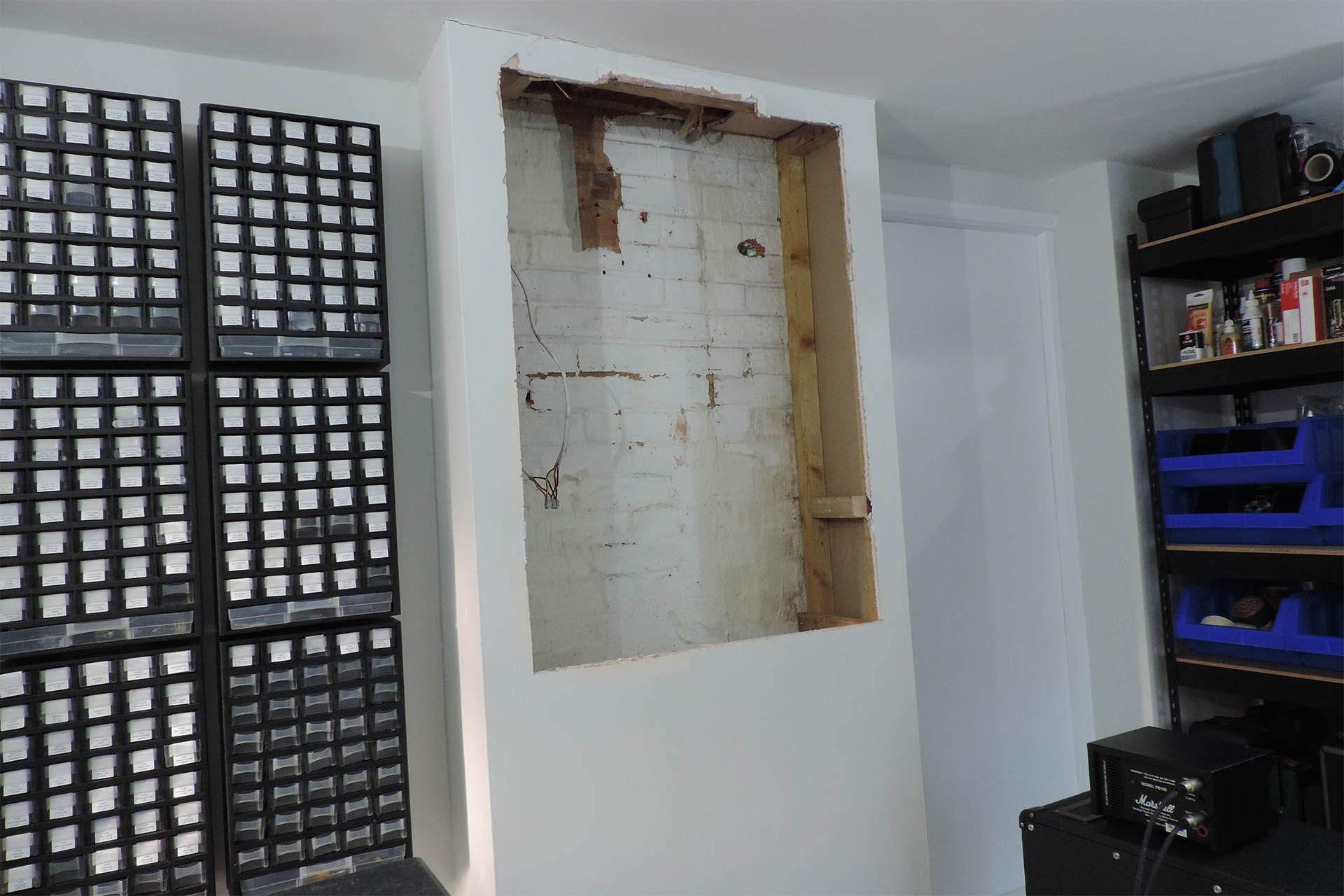
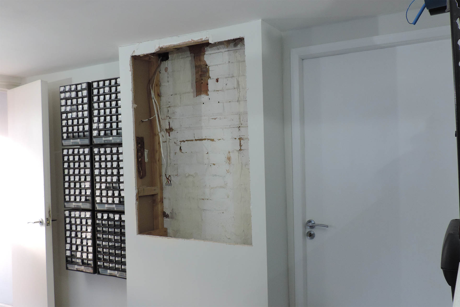
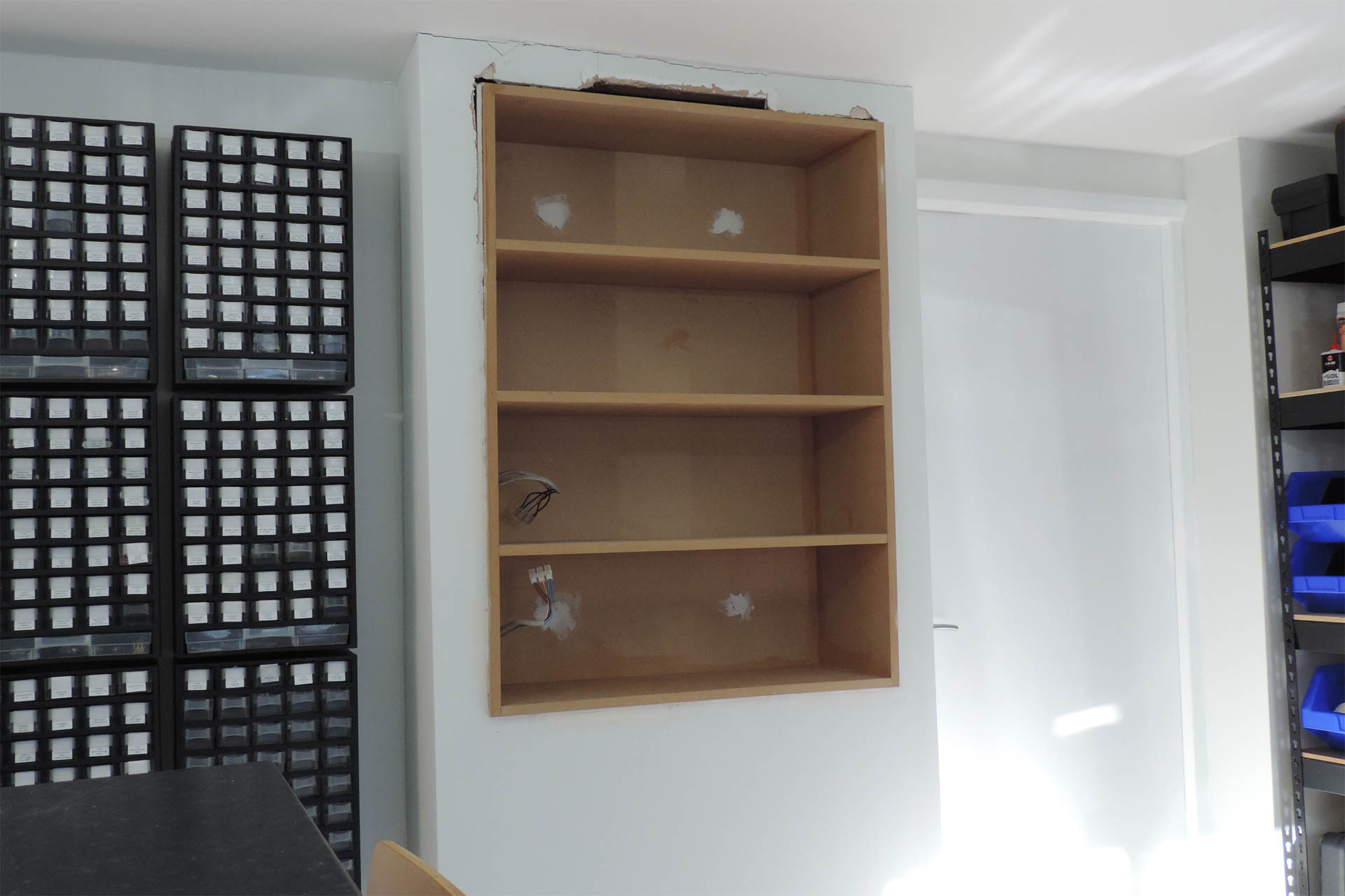
Wanting as much space as possible in the new lab, I decided that the way forward, would be to make a shelf unit, the idea being that I smash out a cavity and (theoretically) slide in the shelf unit... that I'll err... have to make. Did I mention that I hate DIY? 🙁
After finalising the dimensions, I roughly cut out the studwork, with a floorboard saw. There were a couple of redundant gas pipes (not shown in the pictures below), that were cut down with an angle grinder.
After deciding what kind of size I wanted the shelving unit to be, I cut out a cavity in the boxed in emptiness.
Ideally, I’d have liked to take out the whole thing but that would have meant redoing the laminate floor. Did I mention that I hate DIY? 🙁
Here you can see a couple of mains cables hanging down from the ceiling. These are conveniently connected to the ring and so I'm going to take advantage and make a charging point on the shelving unit.
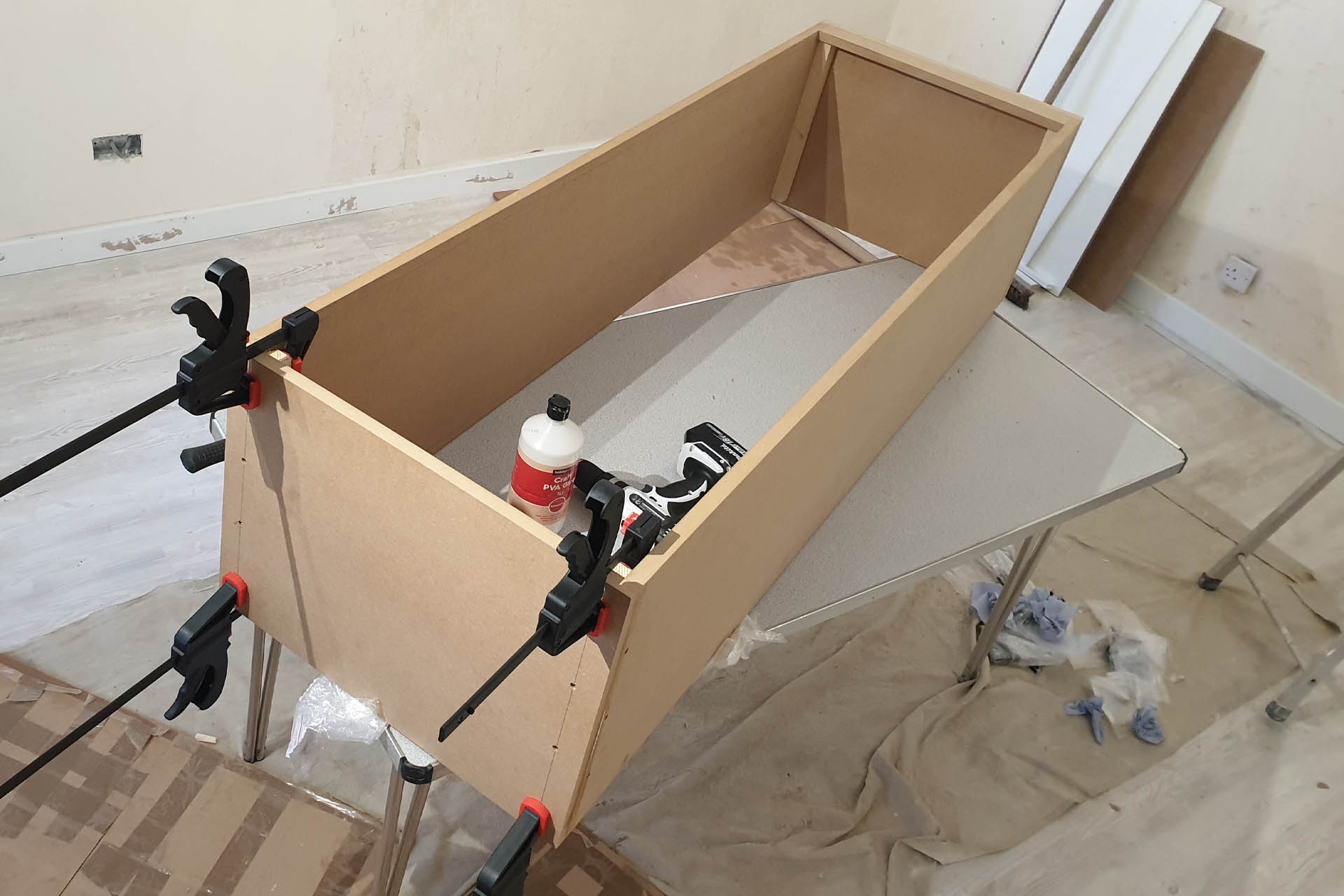
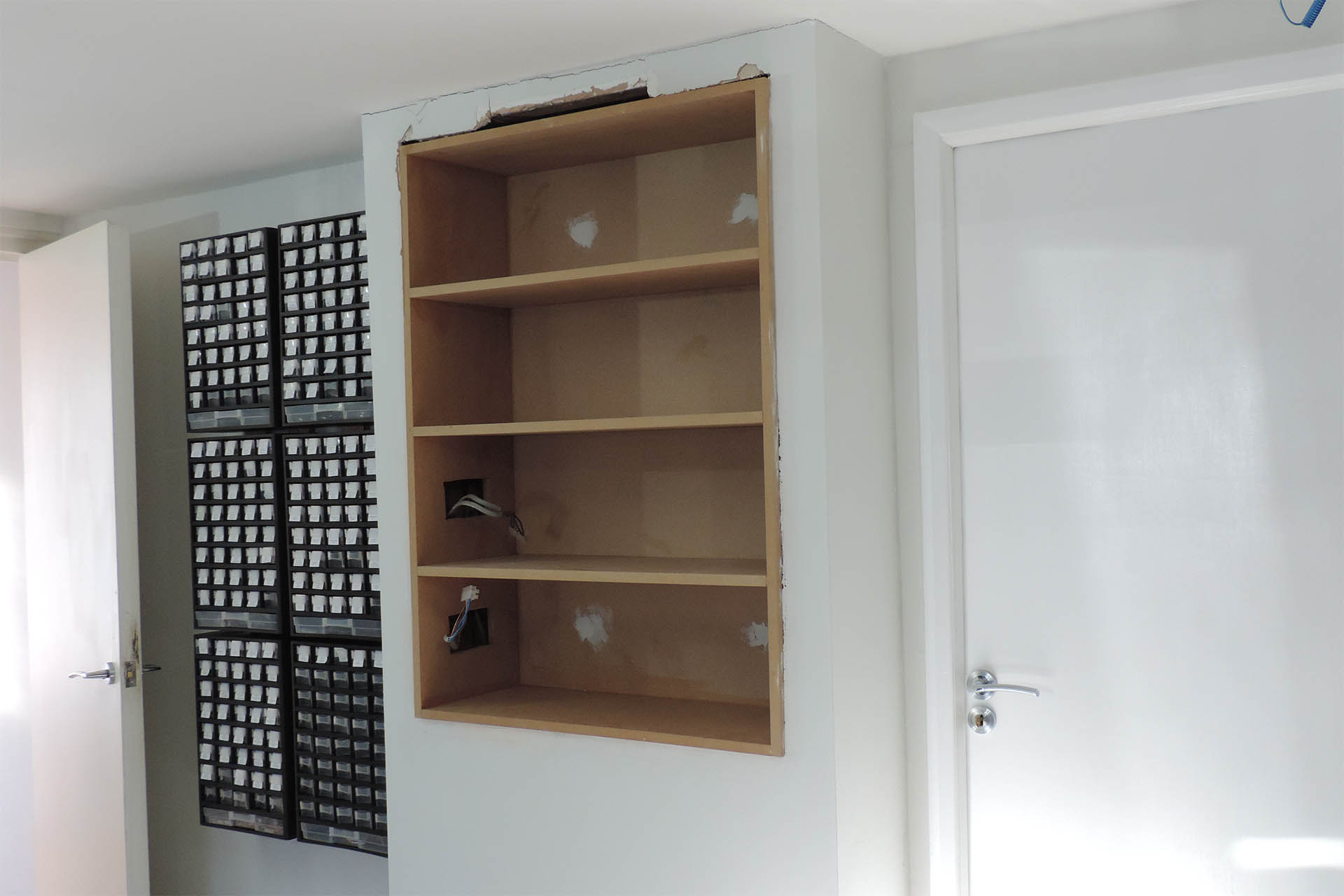
I then designed the shelf unit and originally was going to use conti board but changed my mind in favour of MDF. I picked a 'cut-to-order' supplier that I found on-line and submitted my requirements. There are loads of companies that offer this kind of service but I'm pleased I settled on MDF Direct. The perfectly cut 18mm MDF arrived the next day and was very well packaged, with plastic caps protecting the otherwise vulnerable corners. The beautifully cut MDF arrived the next day but it all stayed wrapped up for a week or so while I mustered the courage to get going on this project. Stupid really as I'd already carved out the bloody wall, duh!!!
Then one evening after finishing some repairs, I thought “what the hell?” I unwrapped the MDF and a few hours later, my shelf unit was glued and screwed together and suddenly taking shape. Oh my God! I’ve actually done it... and it looks and feels bomb-proof!!!
And then one night... I was just inspired!
As I had in my previous lab, I wanted a charging station so since there was electricity in the cavity, I made a couple of cut-outs in the shelf unit, to take two double-gang power outlets with integrated USB charging. I had to hunt around for cavity backboxes (otherwise known as dry lining backboxes) that would fit into 18mm, though.
My wife Julie, gave me a hand to lift the shelf unit into place and slide it in on the supports I had made at the bottom of the cavity. I marked four screw points on the wall and then we pulled out the unit.
BLIMY!!! It fits!
After drilling and then sinking in four rawl plugs, we lifted the unit and slid it back into place again. While Julie supported the shelf unit, I quickly secured it to the wall with some chunky screws.
Wow! It’s actually in!
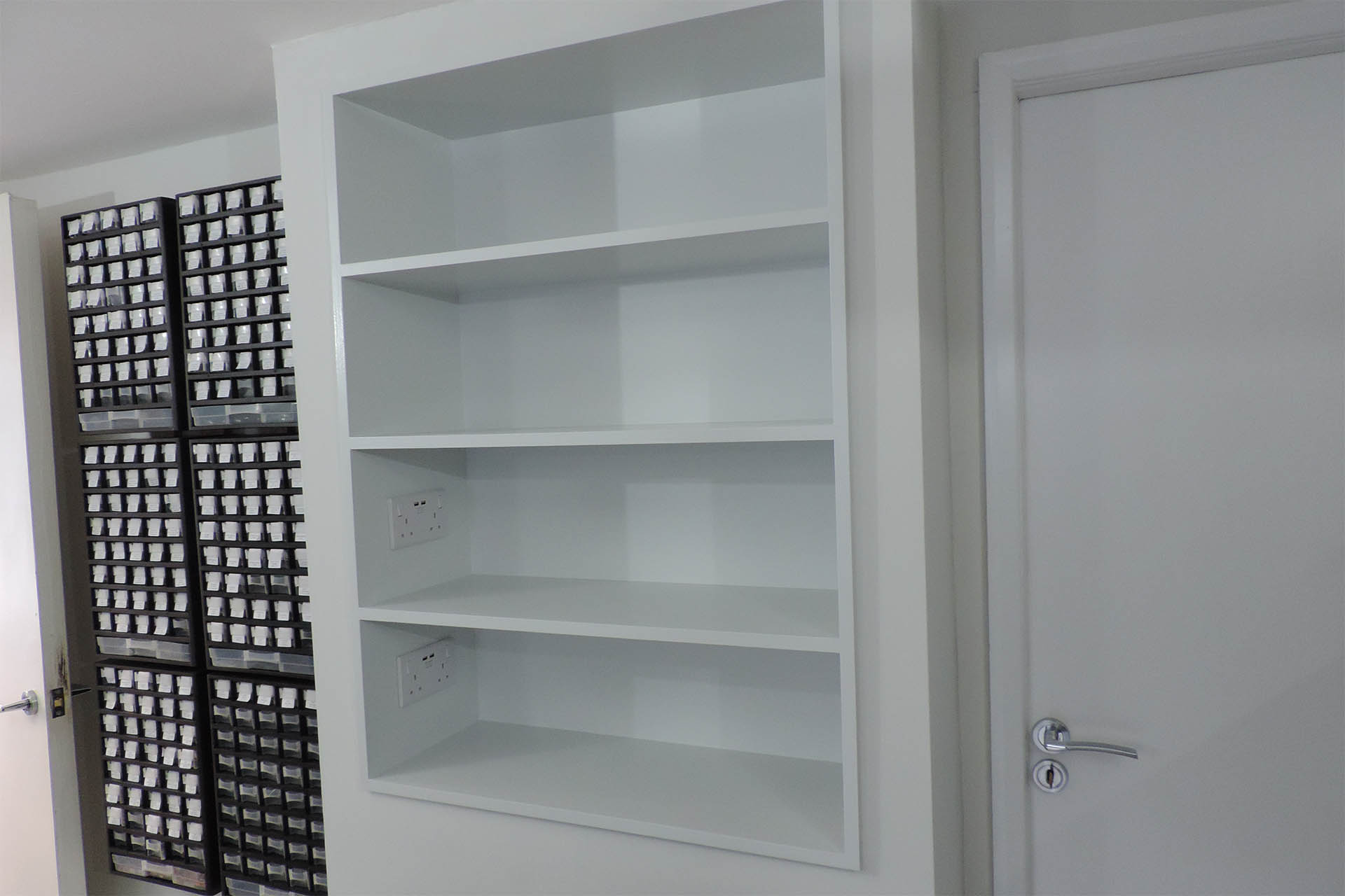
And doesn't look too bad. The shelves are square and level, too.
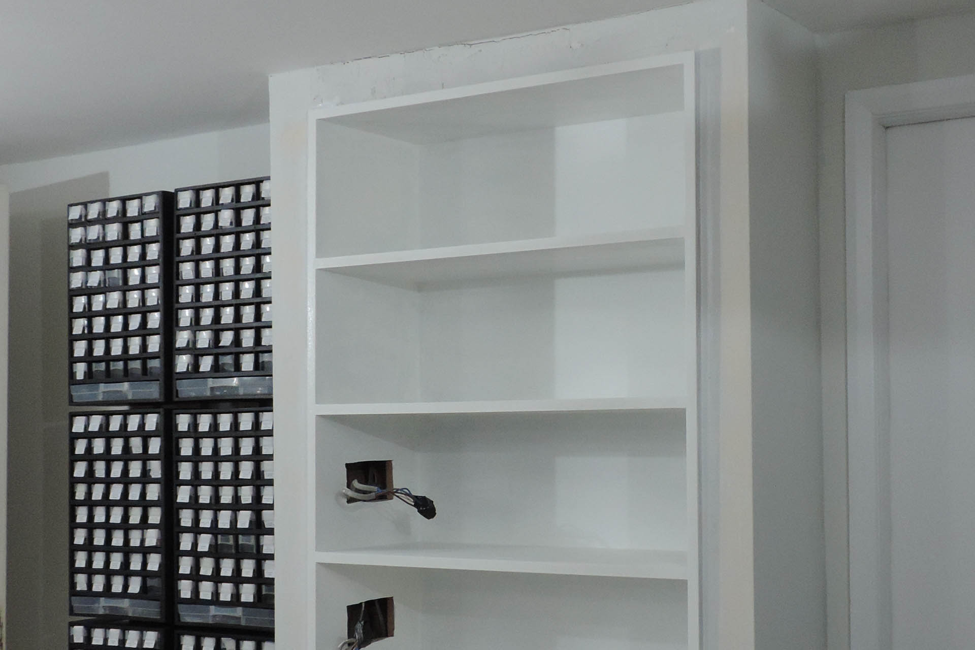
Over the next few days, I primed and painted the cabinet, finishing off with an eggshell version of the matt emulsion that the rest of the room was painted with. I would have normally used a satin paint but figured that the eggshell would be a little more robust.
I had a lot of touching up to do which included filling and sanding, specifically between the top of the unit and the ceiling.
I don't know if this was necessary but I decided to put on a couple of coats of MDF primer before I painted the unit. You can also see that I started filling in and making good the area above the unit, just under the ceiling.
When I originally smashed out the cavity, there was a piece of wood at the top which tried my patience and well, I kind of damaged the plasterboard trying to get it out.
And finally! I used an eggshell version of the emulsion grey (swansdown) which the rest of the lab is painted with.
Anyway, I took my time finishing off and making good. To be honest, I’ve stunned myself with the results. They say that success breeds success but I have to say… I still hate DIY!!!!
The two lower shelves have mains and integrated USB charging, for gadgets, phones, electric screwdrivers, etc.
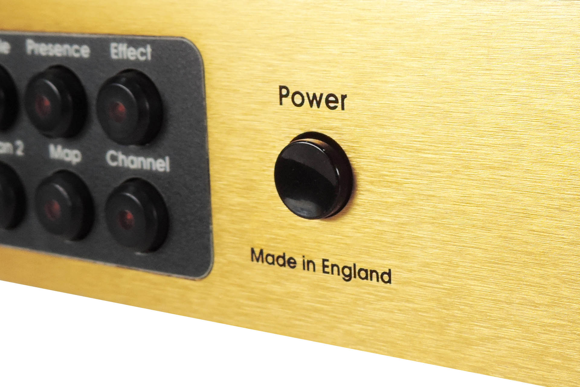
Every since I launched my replacement knob and bezel sets for the JMP-1, people have asked if I can supply either the original or a Marshall JMP-1 replacement power switch button.
Well the original button isn't available anymore but relating to JMP-1 fans' desperation, I persevered, looking for a suitable alternative.
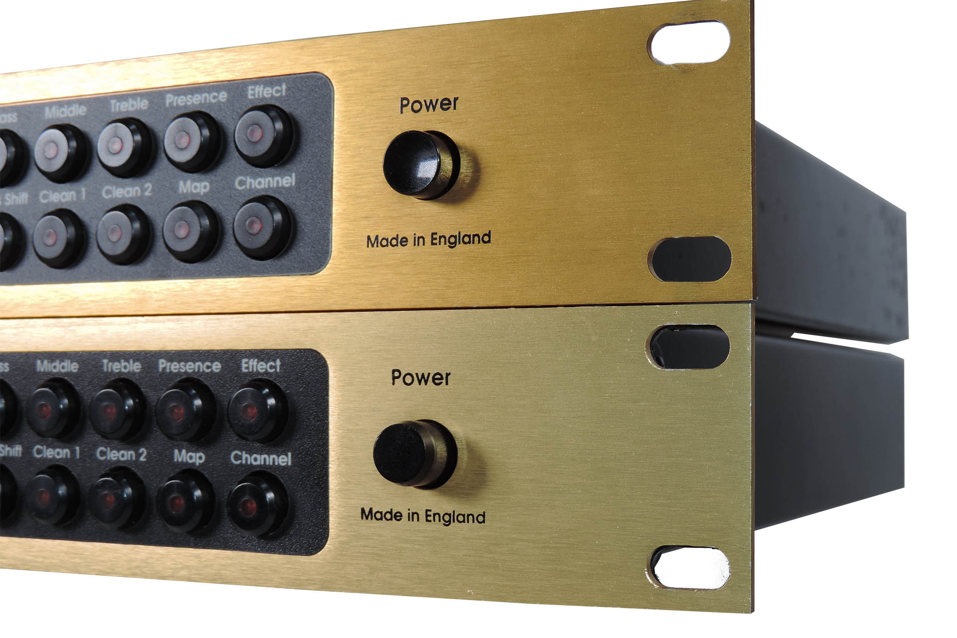
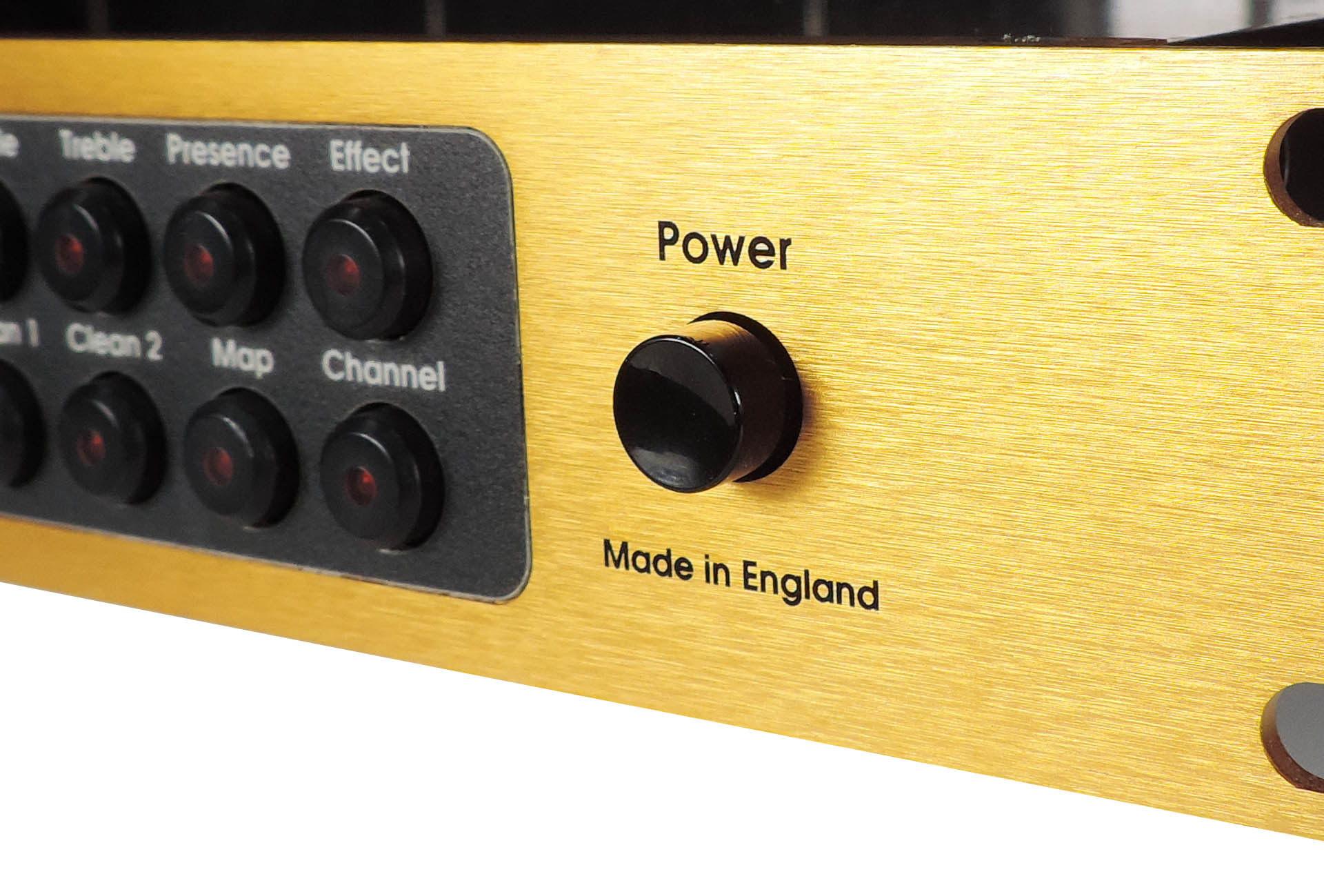
The bottom JMP-1 has the original power switch button. With a slightly lower profile and indented top, my replacement power switch button isn't absolutely identical but it's still a pretty good match.
A few days ago, I think I found one! Three or four millimetres shorter than the original, it does actually fit but when depressed, sits a little closer to the front panel facia than the original. Apart from that, it looks good and works. 🙂
My replacement power switch button for the JMP-1 in the 'OUT' (off) positionMy replacement power switch button for the JMP-1 in the 'IN' (on) position
As such, my Marshall JMP-1 replacement power switch button has now been added to both my performance and studio knob and bezel sets. You can check them out here.
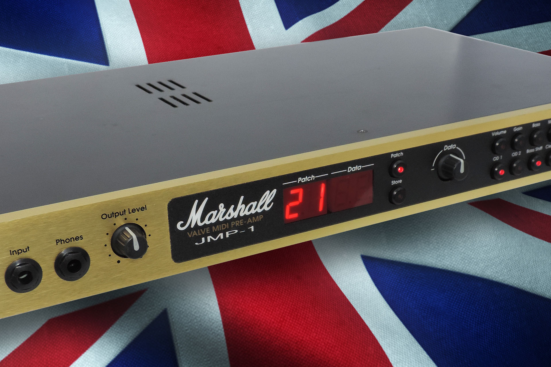
Many will know that I have a thing going with the Marshall JMP-1. Despite having a small collection of vintage Marshalls, I keep mon coming back to this little box only too often.
I know the Marshall JMP-1 inside out and do what I can to keep those that are still breathing, going a little longer. 🙂
I've designed a couple of things for this special little box like my Eclipse bounce eliminator which stops the data entry knob from jumping or skipping. Then there's my recently released PML-TX01 replacement transformer which runs a lot cooler than the original, thanks to the use of a higher quality material for the laminates. Unable to convert the outputs to balanced, due to a severe lack of space and appropriate PCB connections, I promote my Transformer Coupled Interface Type 1, as the perfect interface to connect your JMP-1 to your desk or DAW.
I regularly keep an eye out for developments in the world of JMP-1 and sometimes come across little jems like this cool editor: http://jmp-editor.mattzick.com/
And of course if you just need your JMP-1 looked at, don't hesitate to contact me.
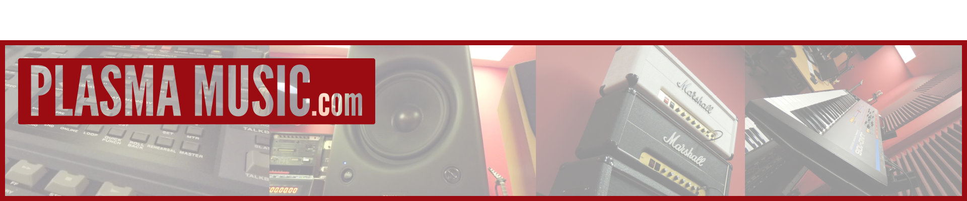
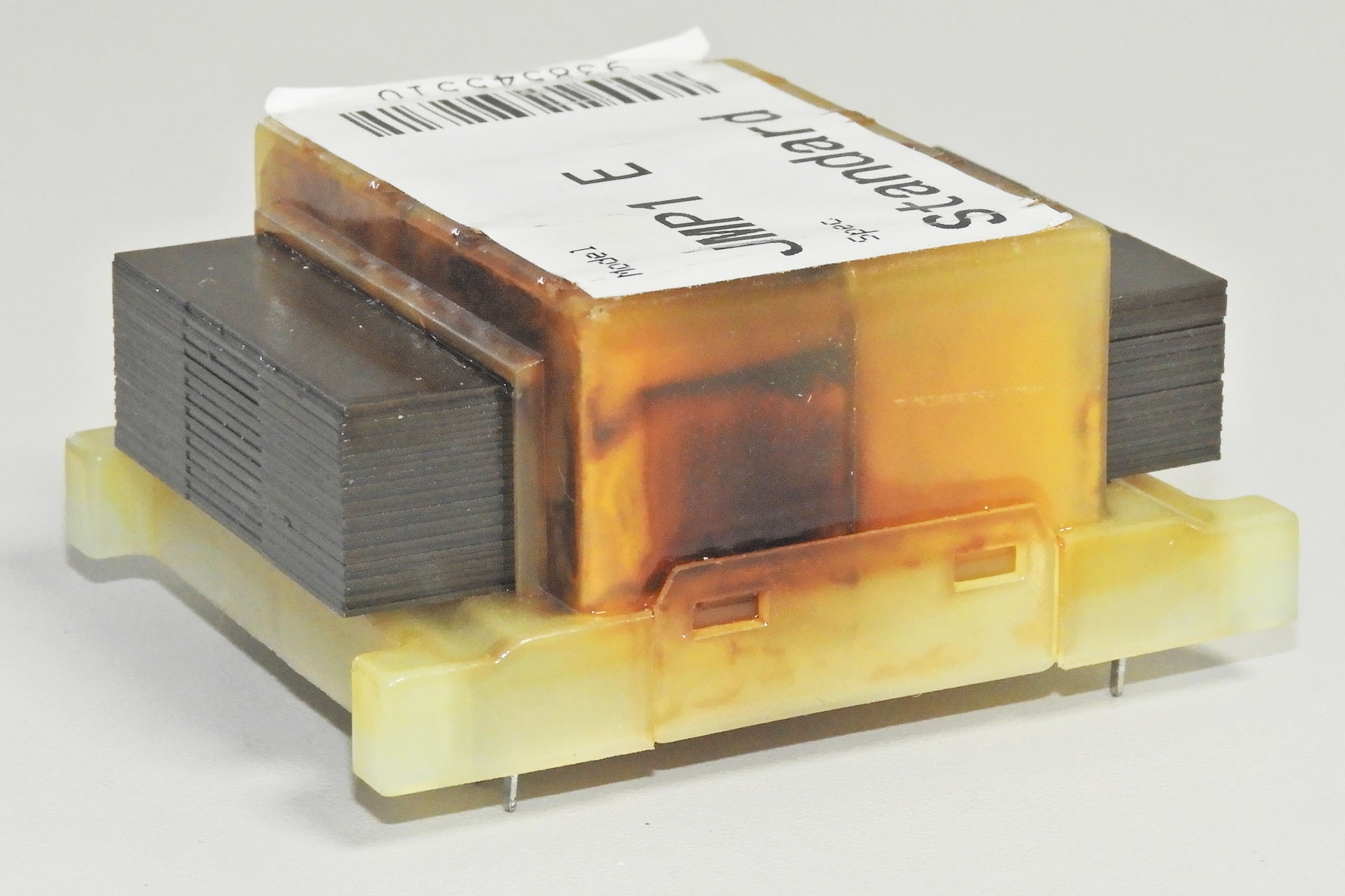
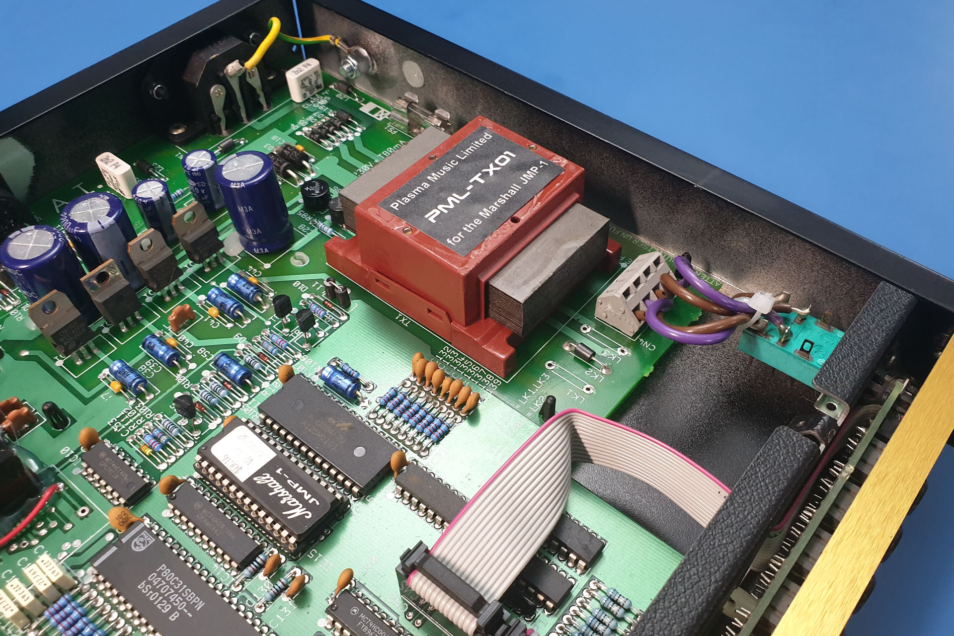
And here it is... my PML-TX01 transformer for the Marshall JMP-1.
This project has taken months but after tracking down Graham Sopp, the guy who designed the original TXMA-00014 JMP-1 transformer, I'm delighted to announce that my PML-TX01 upgraded transformer for the Marshall JMP-1 is now available, featuring laminates made with a higher quality material.
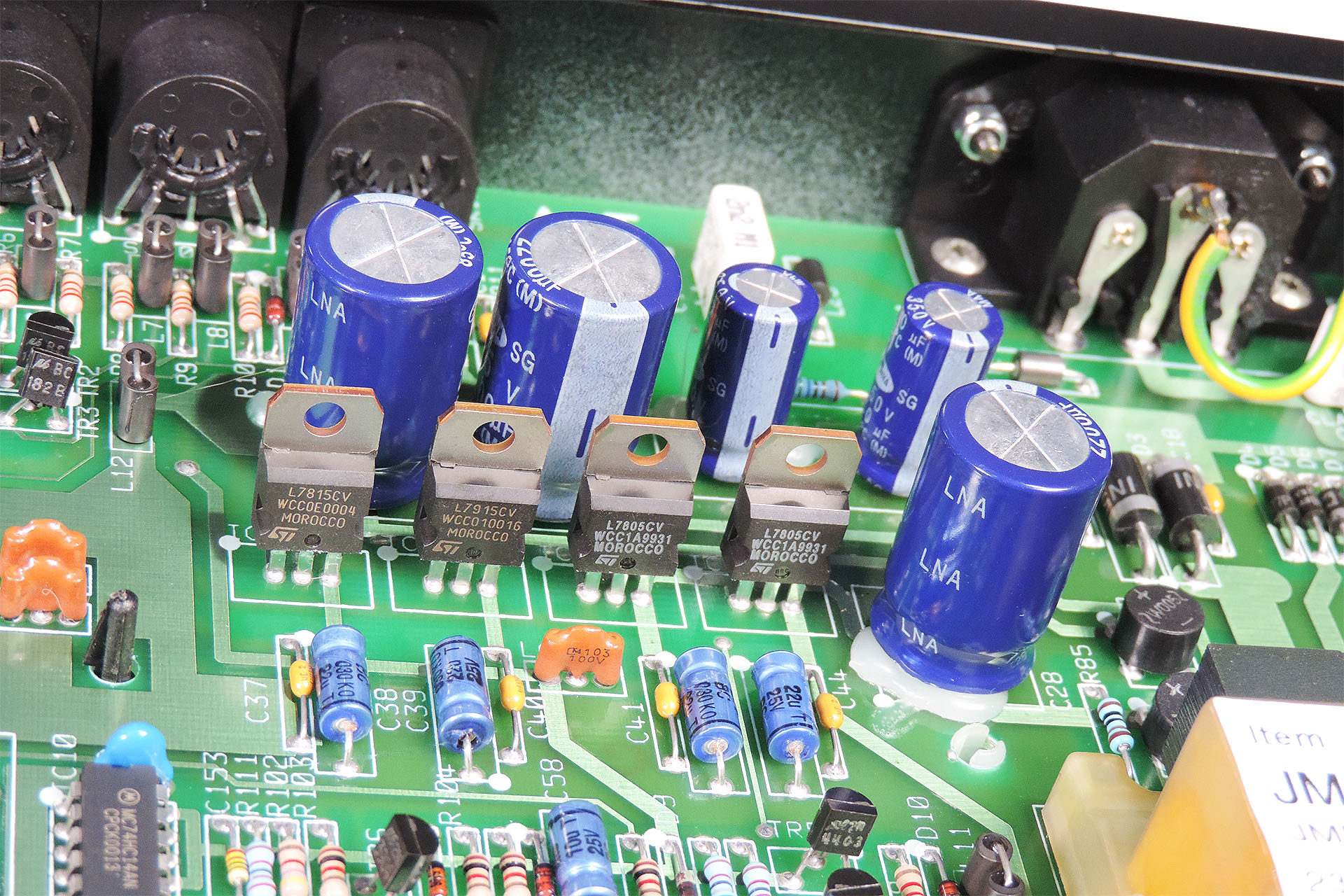
You don't need to be a rocket scientist to notice that the original transformer in the JMP-1 is not particularly stressed. Just take a peek at the regulators and you'll notice an obvious lack of heatsinks suggesting that the current draw from the supply lines is far from excessive. Measuring the input voltages to the regulators indicates that the voltage drop across them is not too much and of course we all know that the valves take very little current.
The regulators in the JMP-1 don't have any additional heatsinking because they don't run hot.
So why then, does the JMP-1 transformer get so hot?
Well, it's due to the fact that the transformer's laminates oscillate. That's right. They oscillate so much that apart from the hum, a considerable amount of heat is also produced.
WARNING - THERMAL MELTDOWN IMMINENT
I've heard of people putting rubber or foam between the top of the transformer and the inside of the JMP-1's lid, to reduce the the hum. DO NOT DO THIS!!! I've just mentioned that the oscillating laminates produce a huge amount of excess heat. Whilst the hum is annoying, with the top of the transformer in contact with the lid, any heat produced at least has a dissipation path. If you put anything on top of the transformer, it'll act like a blanket and you're just going to burn it out quicker. 🙁
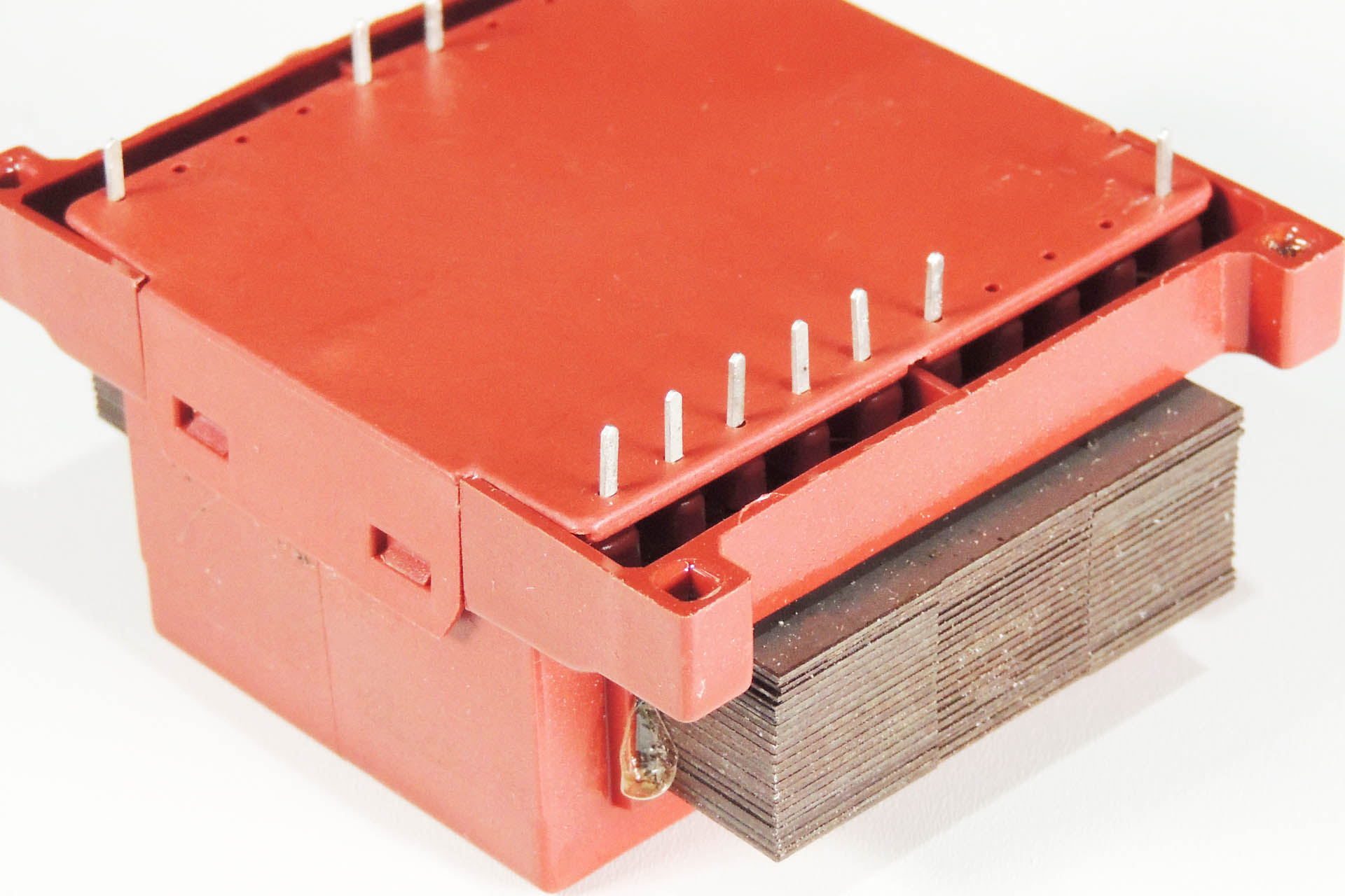
Pictured below is an original TXMA-00014 that I removed from a faulty JMP-1. Displaying random behaviour and poor sound quality, when I opened her up, the results of thermal stress were quite obvious.
I spent a lot of time looking at the mystery of the Marshall JMP-1 humming transformer, refusing to acknowledge any issue with the laminates as I just didn't want to believe it. Once the penny dropped though, it all made sense.
Made in the same factory as the original, my PM-TX01 is of course pin-for-pin compatible with the Marshall TXMA-00014
It took a while but my first batch of PML-TX01 transformers is now here. With considerably less hum and heat than the original Marshall TXMA-00014, I thoroughly recommend that you consider this upgrade.
Looking quite at home, my PML-TX01 fits easily into the JMP-1.
MARSHALL JMP-1 VOLTAGE SELECTION
I regularly receive two questions from those interested in my PML-TX01:
Is the PML-TX01 replacement transformer for the Marshall JMP-1, 240V or 120V?
Are the voltage selector components diodes, ferrite beads or just fancy wire links?
Here are the link locations to select the voltage rating of the primary windings for the transformer in a Marshall JMP-1. The example shown is set to 230V.
The answer to the first question is, just like the original TXMA-00014, my PML-TX01 has two separate primary windings, each rated at 115V. So…
EUOPEAN / UK VOLTAGE SELECTION. Wired in series, the primary becomes a single 230V winding which is suitable for 220V (Europe) and 240V (UK, Australia). To wire in series, connect ONLY LK2.
USA / CANADA / JAPAN VOLTAGE SELECTION. Wired in parallel, the primary becomes a single 115V winding suitable for 120V (USA and Canada), 100V (Japan). To wire in parallel, connect LK1 and LK3.
It's quite easy to implement 240V to 120V conversion, or 120V to 240V, for example. Those eighties style wire links can make things look complicated but the original links were JUST WIRE LINKS and nothing else, so you can use wire.
Looking from the pin side of the transformer, here are the voltage selection links and secondary transformer voltages. Apart from the higher quality material used for the laminates, the PML-TX01 is a direct drop-in replacement for the original Dagnall TXMA-00014.
It's important that the input voltage selection is chosen properly so below things are drawn that may be more representative of what you might actual see in your JMP-1.
Here's a diagram which resembles the actual physical layout of the power feed and primary voltage selection in the Marshall JMP-1.
SIDE NOTE
One might ask why the two individual primary windings are put in parallel for 115V. Why not just use one winding?
Well, a system uses a certain amount of power. Power is the product of voltage and current: P = V x I.
You can probably see now that if you half the voltage, you'll need twice the current to deliver the same amount of power. Placing the two primaries in parallel does just that, it doubles the current going into the system. 🙂
And lastly...
! ! ! DON'T FORGET TO CHECK THE FUSE RATING ! ! !
So as I've just intermated, the power requirement of a machine is the same whatever the supply voltage. Since power = current x voltage, if you're halving the voltage, you'll be doubling the current.
Don't forget to select the correct fuse rating for your region.
If running at 230V, the JMP-1 fuse should be 80mA (230V x 0.08A = 18.4W).
If running at 115V, the JMP-1 fuse should be 160mA (115V x 0.16A = 18.4W).
'T' stands for 'time delay' so use a time delay fuse.
A WORD OF CAUTION
The transformer is soldered to the now very old, double-sided main board in the JMP-1. Please take care when removing the original transformer. It's a relatively heavy device and the through-hole plating isn't exactly the best quality. The last thing you want to do is strip it!
IMPORTANT
My PML-TX01 upgraded transformer for the Marshall JMP-1 is a high specification drop-in replacement for the original TXMA-00014 only. It is NOT suitable for other pre-amps such as the Marshall 9001.
If you have any questions about my PML-TX01, please don't hesitate to contact me or you can just
This item regularly goes out of stock, I'm afraid but... I encourage customers to back-order. Unfortunately, the crappy e-commerce plug-in I use, only tells the links (like the one above) that the item is out of stock. What 's the bloody point of that?!?!?! So if you want this, then please just visit the PML-TX01 page on my e-store here.
UPDATE - 22nd July 2023
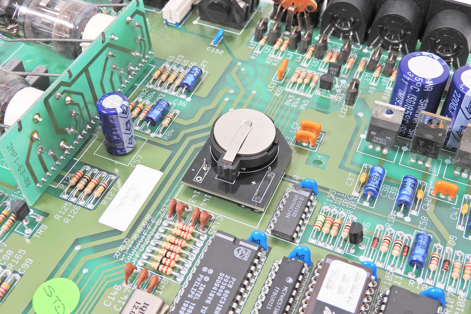
I often get asked about the memory back-up battery in the Marshall JMP-1 and with soldered batteries not really being in fashion anymore, replacements are difficult to get hold of. I therefore decided to knock up a small PCB that mounts into the original battery location but which has a CR2032 clip. This allows for easy battery changing with a standard (you guessed it) CR2032. Measuring the voltage on the battery is a little easier, too. 🙂
UPDATE - 9th February 2024
With so many bits 'n' pieces available for the JMP-1 and always thinking of new stuff to make for our favourite MIDI valve pre-map, I decided to make a category just for the Marshall JMP-1 in my on-line store. You can check it out here.
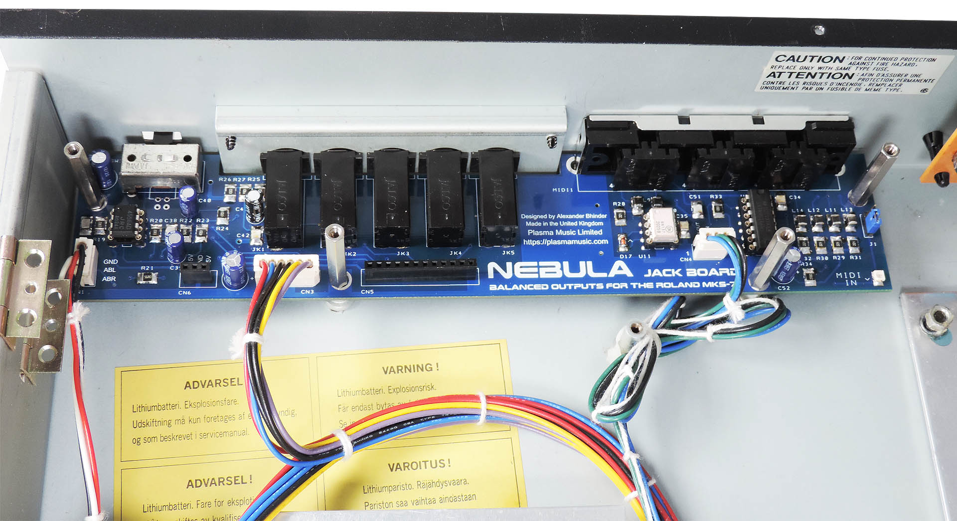
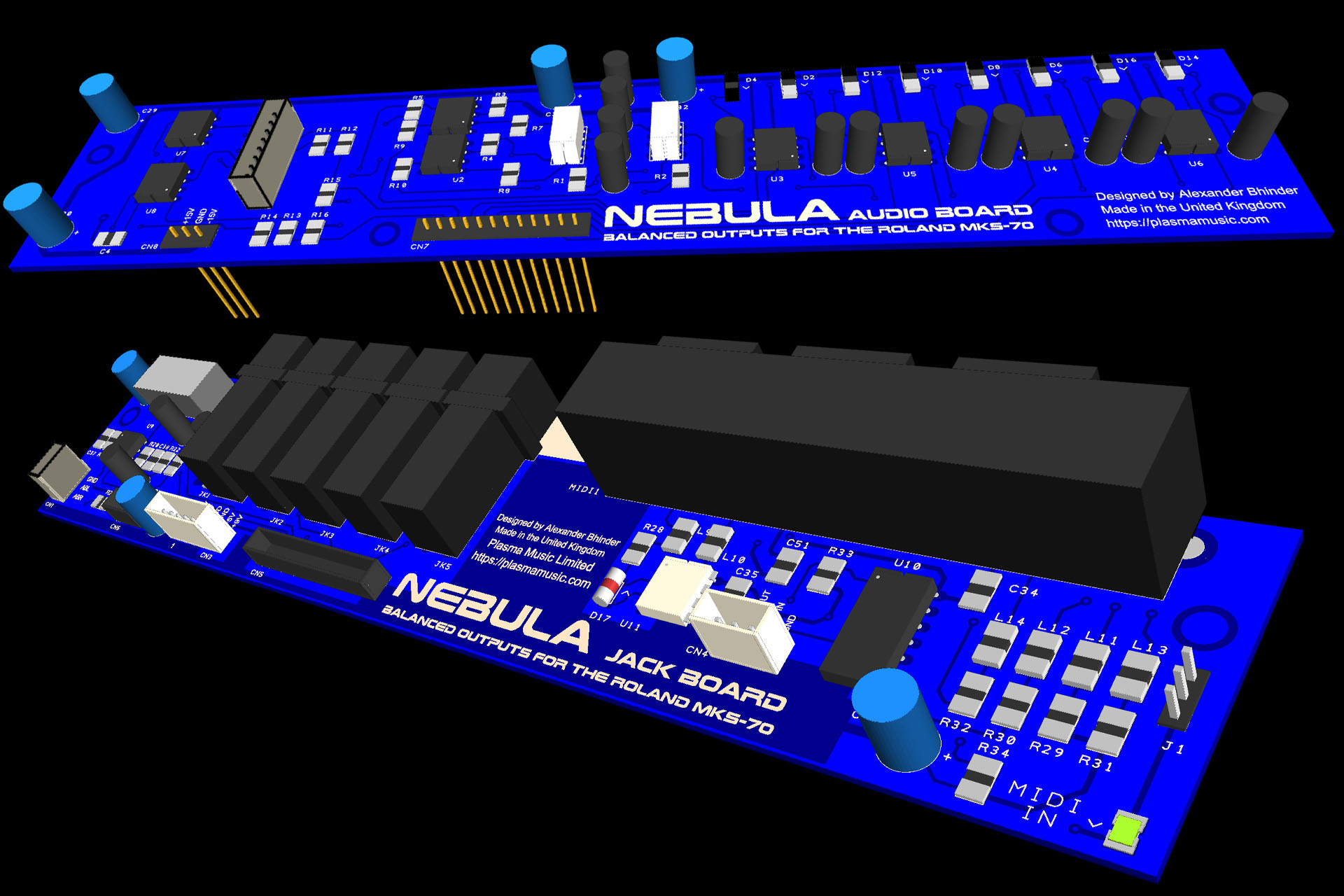
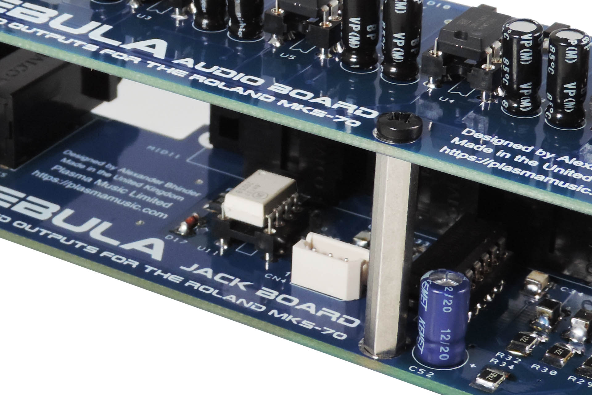
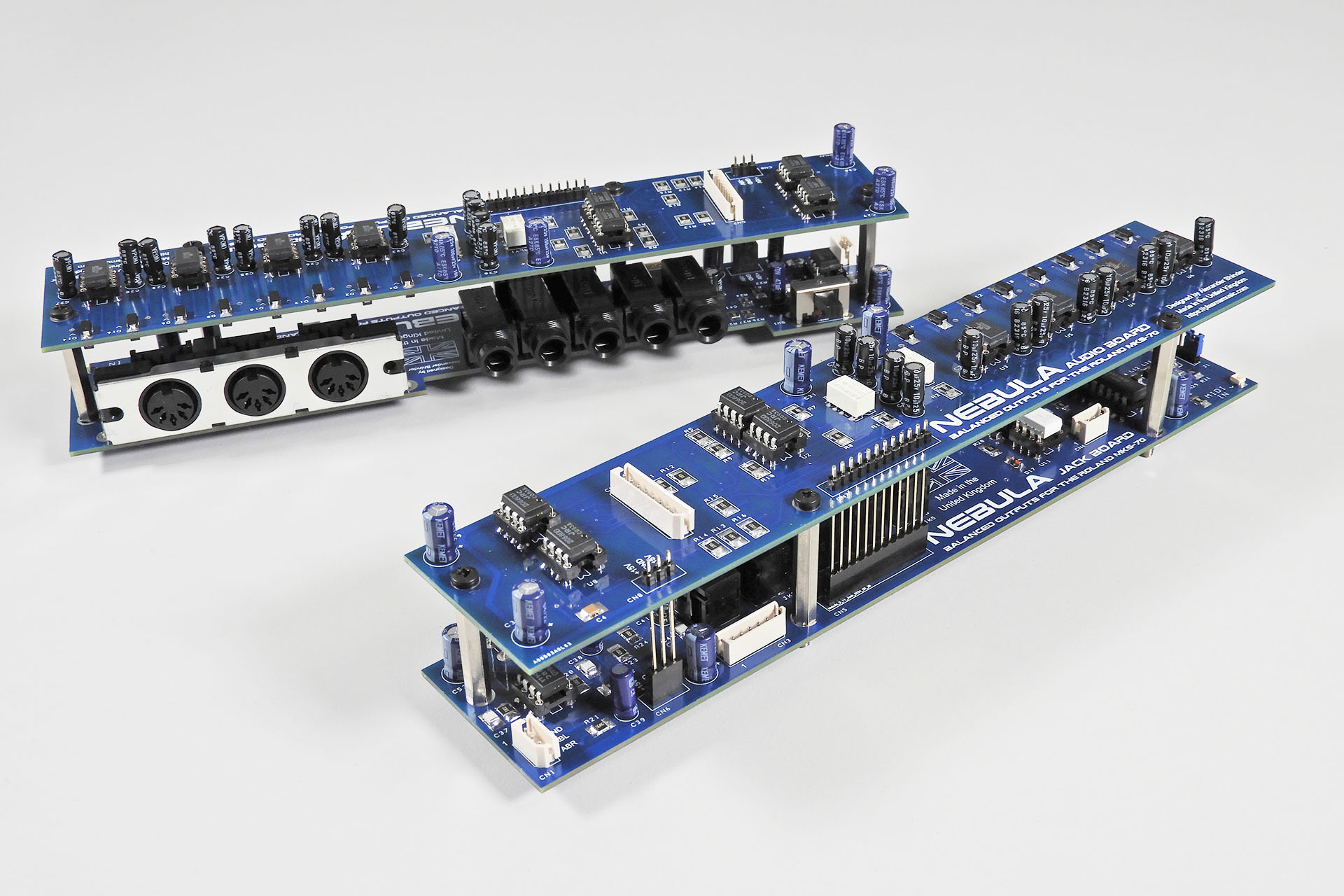
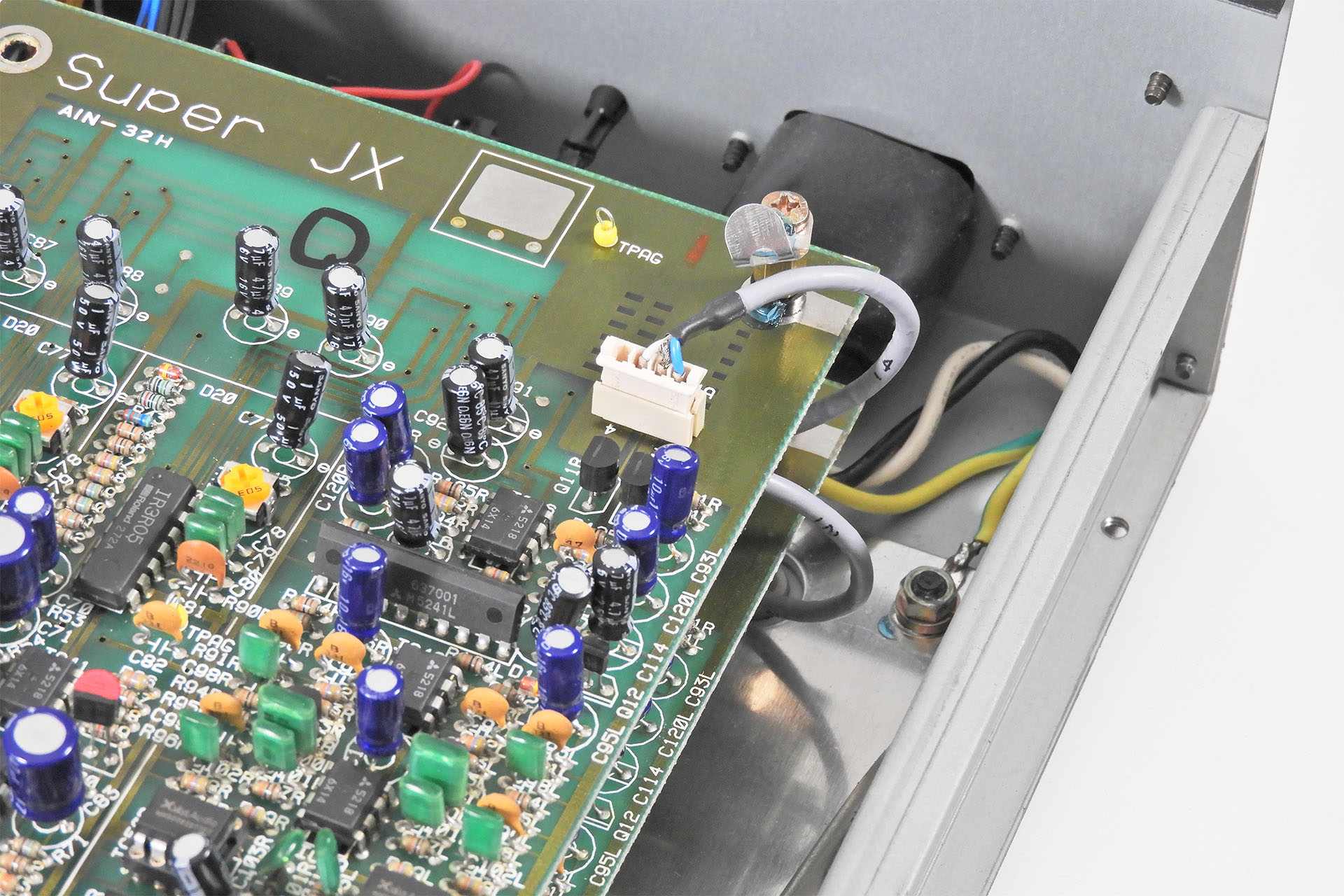
This is Nebula, a new jack board for the Roland MKS-70 with an upgraded MIDI interface and balanced outputs.
Shortly after Christmas 2020, Guy Wilkinson and I were having one of our long and deep chats on the phone. I mentioned an idea to him which he seemed to like. Since then, I’ve been developing my idea and after working in my spare time for seven months, I’m delighted to announce Nebula – balanced outputs for the Roland MKS-70.
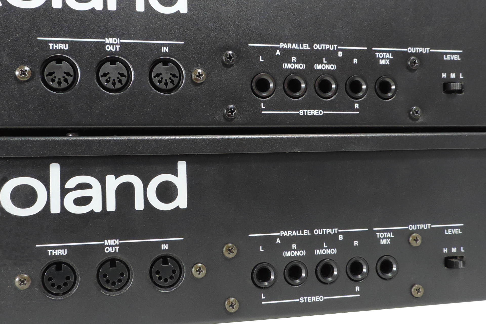
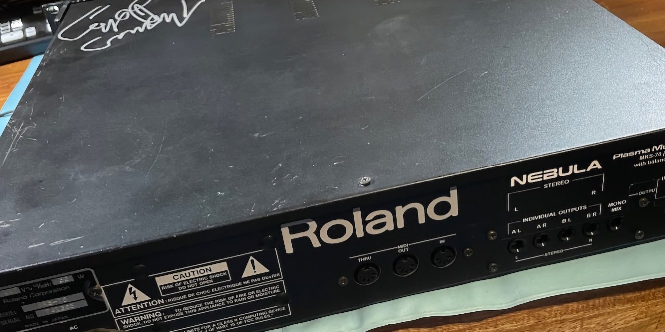
The back of these two MKS-70s look almost identical but one them hides a rather cool little secret.
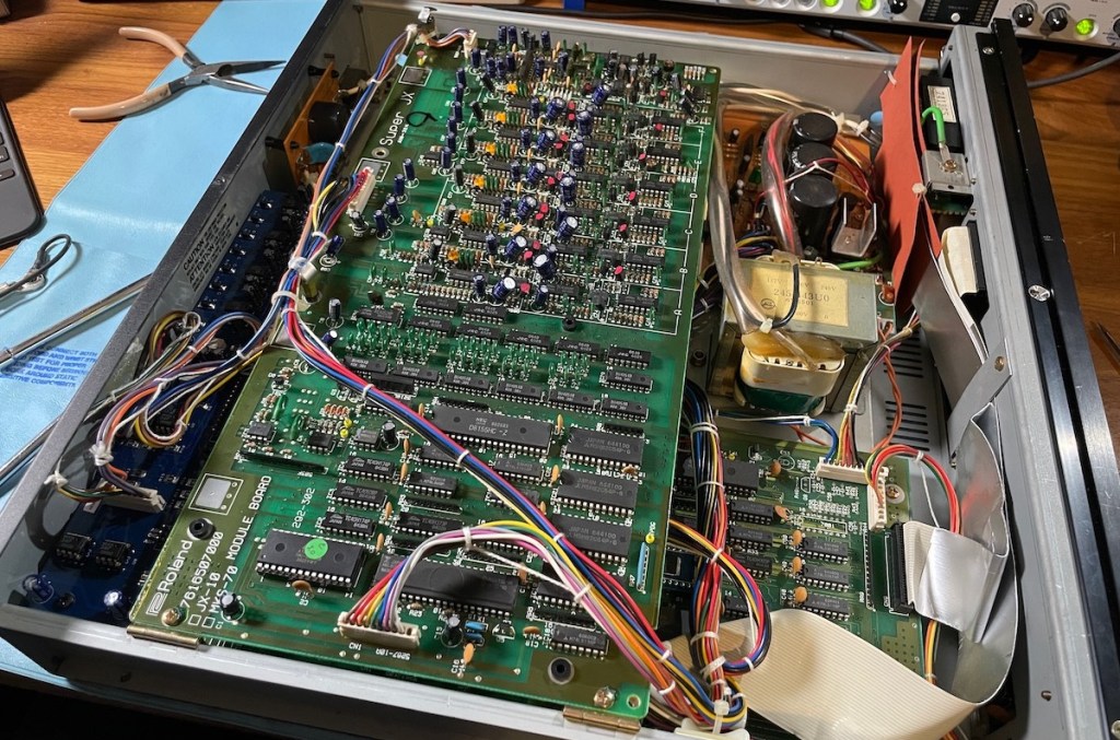
Above, are my two MKS-70s. The bottom one is heavily modified with one of Guy’s OLED display modules, his P0004 power supply, Fred Vecoven’s PWM and his Super-JX flash upgrade. The other MKS-70 is unmodified but…. it does hide a secret. The top MKS-70 is running Nebula which means it has a revised, up-to-date MIDI circuit and… balanced outputs! SERIOUSLY????? Yes... SERIOUSLY!!!! 😀
SO WHY BOTHER?
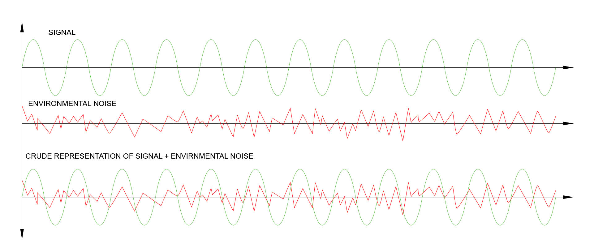
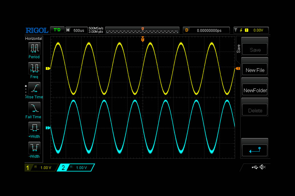
There’s a big advantage to running balanced signals from your sources to your mixing desk or DAW audio interface and that is, an increased immunity to noise.
Environmental noise exists everywhere all the time. There’s human generated environmental noise such as radio signals, noise generated from switching circuits and so on but there’s also a considerable amount of natural background noise.
To screen signal carrying conductors from noise, cabling comprises a shield which is attached at one end, to the chassis of the source device and at the other, to the chassis of the destination device, thereby ‘extending’ the chassis of each device.
The problem is that screening isn’t 100% effective. We want our cables to be flexible and it’s impossible to achieve a 100% screen, while maintaining a good degree of flexibility.
Unbalanced signal is in in green and noise is in red. Unfortunately, noise mixes well with audio signals!
NOTE for all the would-be rocket scientists out there. YES, I'm quite aware that the output waveform doesn't actually look like that but unfortunately packages like Adobe Illustrator aren't able to display a Fourier combination of what they see as a pair of vector traces. That's why I've blatantly written 'CRUDE REPRESENTATION'. In addition, I personally think this representation makes it easier to 'see' what's going on, particularly for the uninitiated.
So where were we? Ah, yes...
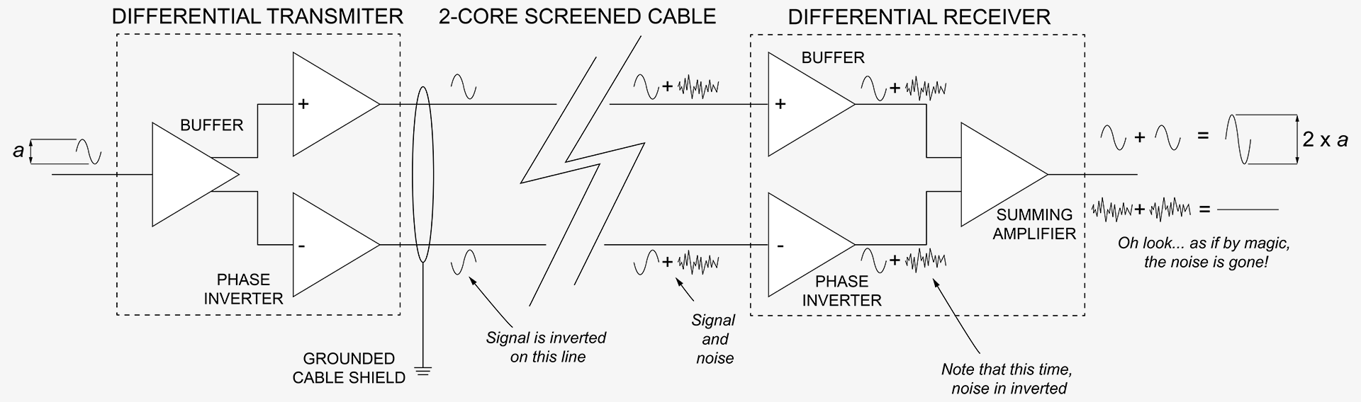
Another approach is that of the balanced line…
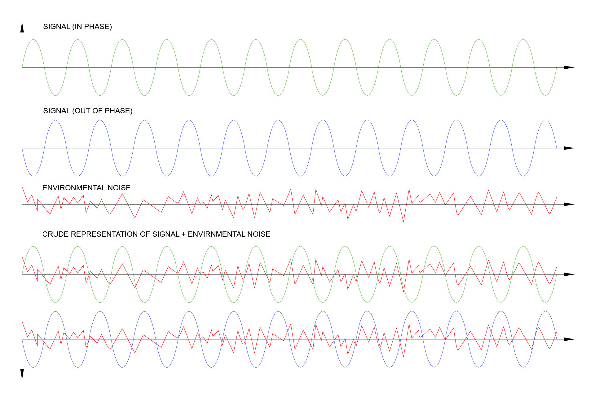
Instead of sending a single signal, we send two signals; one being a copy but 180° out-of-phase with the first and then at the receiving end, we put things back to a single in-phase signal.
Noise is in-phase, everywhere. Nothing is producing a 180° out-of-phase load of noise, right? This means that noise is affecting both the in-phase and out-of-phase signals in exactly the same way.
With me so far? Good.
At our receiving end, the (differential) input stage rejects all signals that appear the same on both the in-phase and out-of-phase lines, this being… noise and ‘passes’ everything that is 180° out-of-phase… our signal.
Similar to the previous figure but the out-of-phase signal is in blue. Now, take a closer look at the last pair of waveforms and you'll notice that noise (in red) is in-phase on both signal lines. When fed into a differential amplifier, any common phase signals such as this noise, are 'filtered' out or rejected .
So how cool is that?
I get asked this a lot but after reading the above, I hope you now understand that balancing the outputs of your equipment will NOT get rid of noise generated by your equipment. It’ll only reduce noise that's picked up between your source and destination devices.
A figure known as the Common Mode Rejection Ratio (or CMRR) is the measurement in decibels, of how much signal that's common to both phases is filtered out by a device.
I don't like reinventing the wheel but since the jack-board not only has the MIDI sockets on it but also the MIDI interface hardware, I figured this might be an opportunity to review this thirty-five year old circuit.
Designing a new jack-board for the MKS-70 with balanced outputs was also an opportunity to potentially 'modernise' the MIDI circuit.
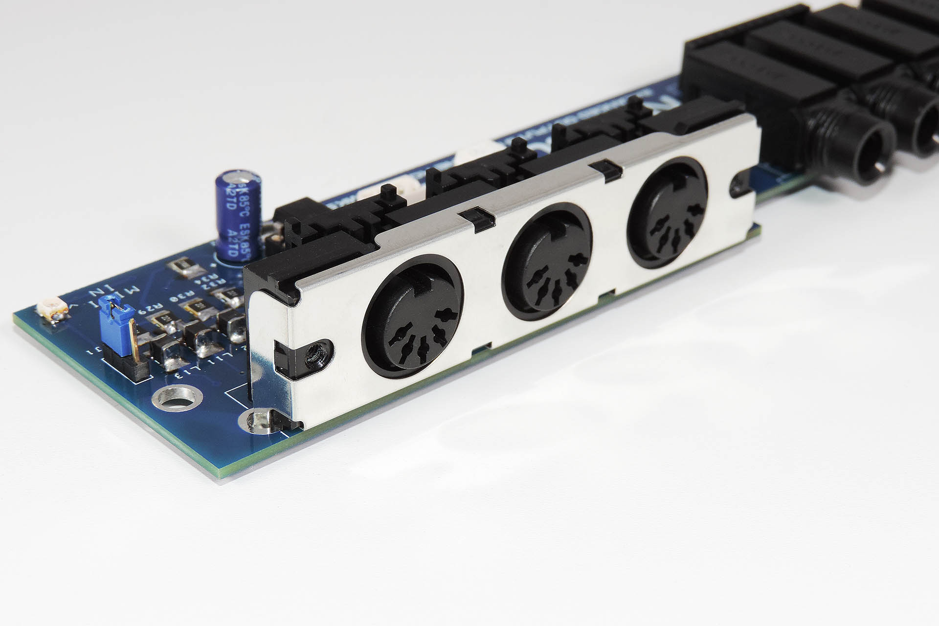
So anyway, there were a couple of initial design challenges. For example, the sockets on Nebula had to line up perfectly with the existing holes in the MKS-70 rear chassis.
Well luckily, a non-switching, 3-pole version of the original jack sockets still seems available. A bonus is that they’re the same size as the original 2-pole sockets. A version of the triple 5-pin DIN array is also still available. This was all really a big deal. If I couldn't get hold of those sockets, Nebula might not have happened because other 3-pole sockets are much wider than the original 2-pole (unbalanced) versions.
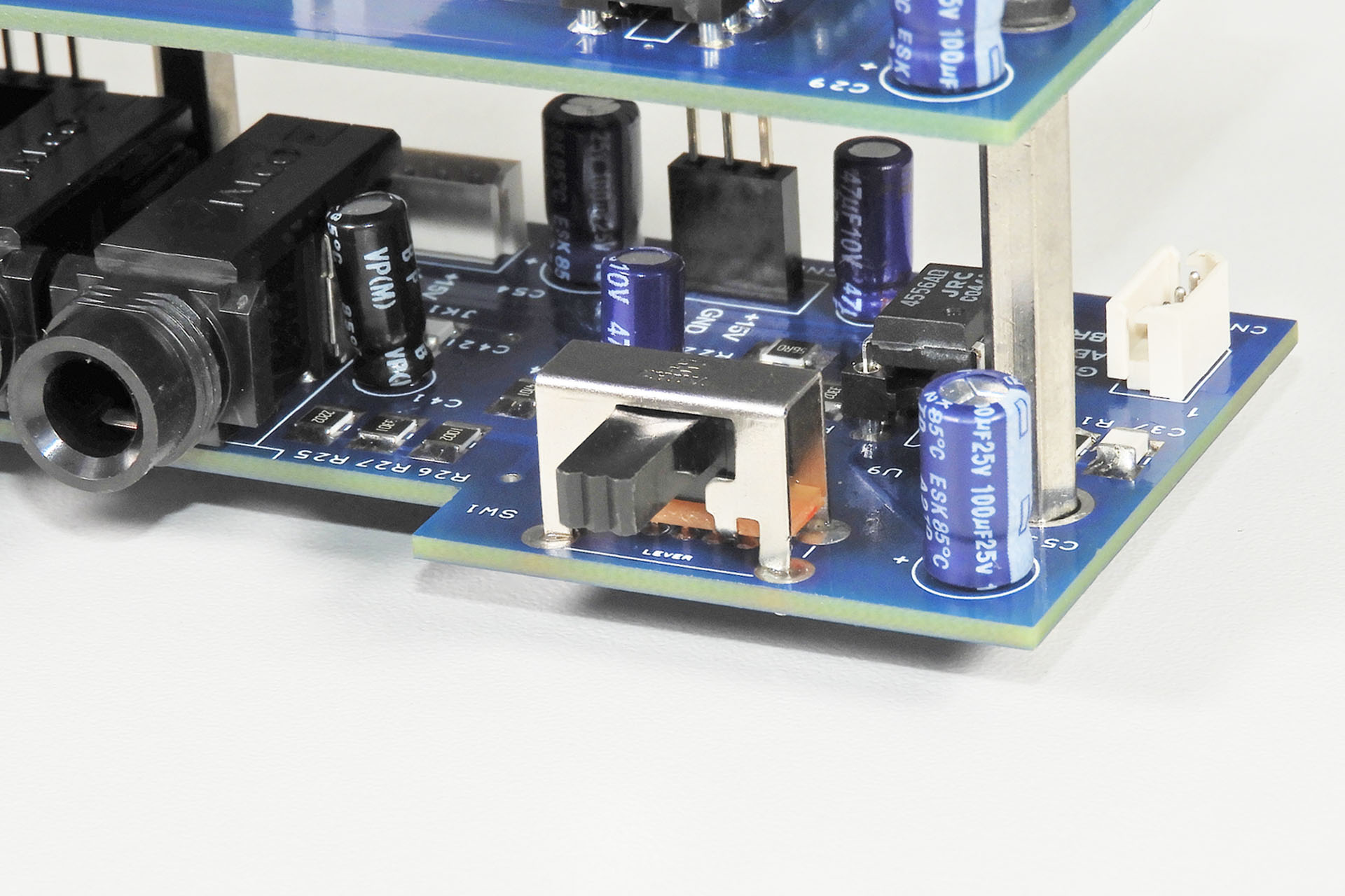
Then the obvious problem; there isn't exactly a lot of room to play with at the back of the MKS-70. How am I going to get a whole load of chips in such a small space? Even if I use SMDs, there's not a lot of room here. It seems like "the only way is up" and so I made the decision to build a double-decker (stacked PCBs) system.
Getting Nebula's PCB to fit, ended up being quite expensive. Everything had to line up properly and with four internal screw posts, six sockets and a switch, I must confess that it took me four attempts to get it all right. That's a lot of prototype PCBs! 🙁
I usually get this kind of thing right first time but it took four attempts to get Nebula's bottom PCB to fit properly. No doubt the most expensive part of the project.
Back in the eighties, part of Roland’s design philosophy was to always support live music and believe it or not, even huge machines like the MKS-70, were designed with a mono-mix output, which could be fed straight into an amp, thereby allowing musicians to take their equipment down the pub for the odd gig. Madness, I know but you have to hand it to Roland for putting performing musicians first.
I’ve respected that philosophy and so the mono-mix output remains unbalanced.
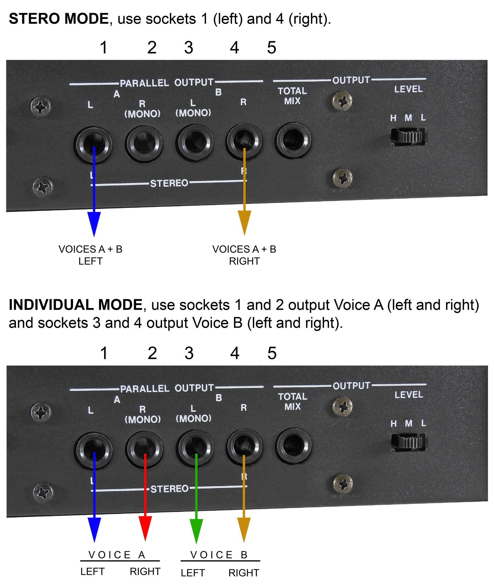
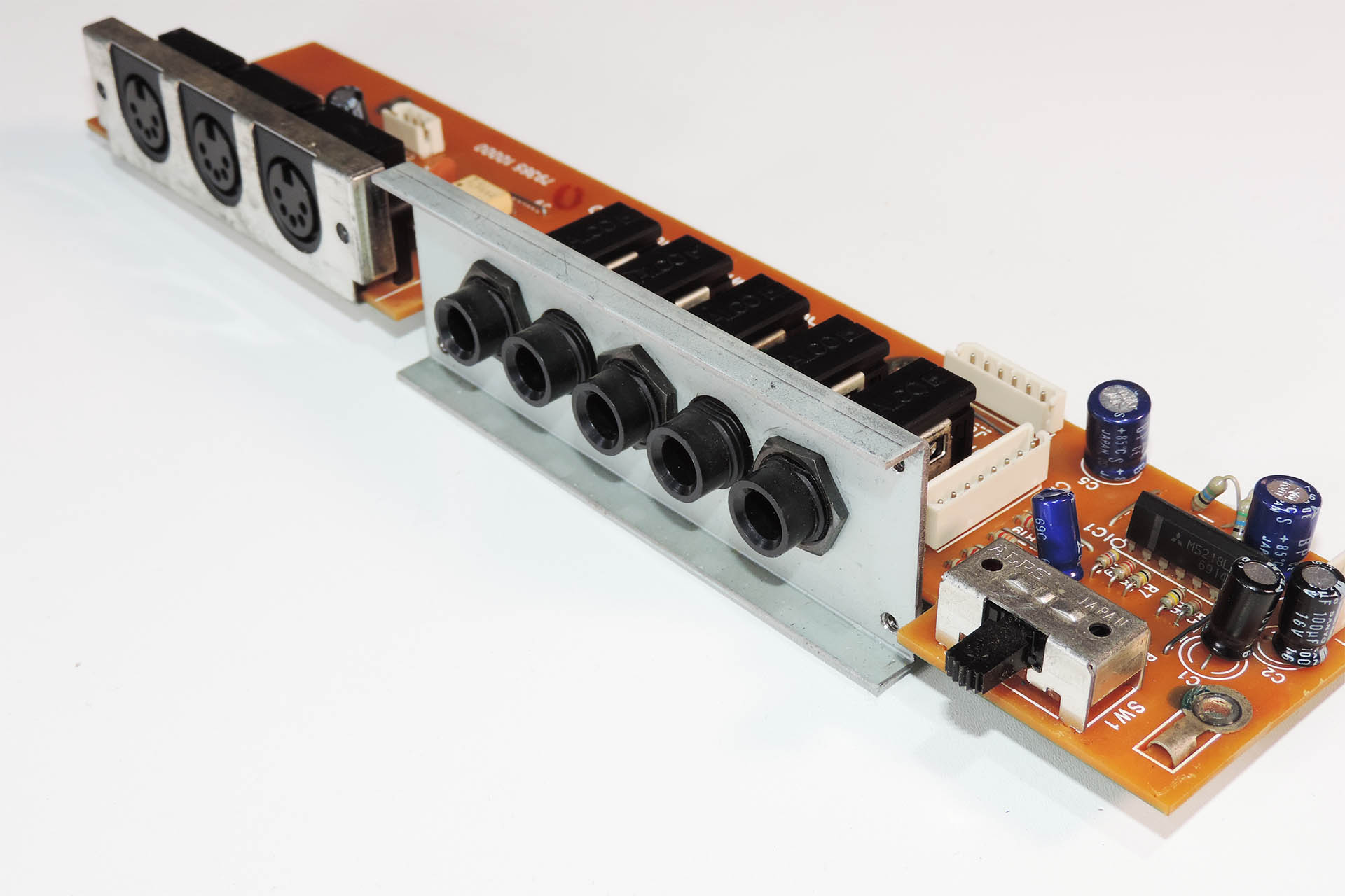
Roland handled the switching of the outputs from stereo to individual, rather cleverly, by using switched, 2-pole jack sockets and a simple but effective array of resistors. Depending on which jacks were used, the MKS-70, either output a stereo pair or four individual outputs; Voice-board A left, voice-board A right and voice-board B left and voice-board B right.
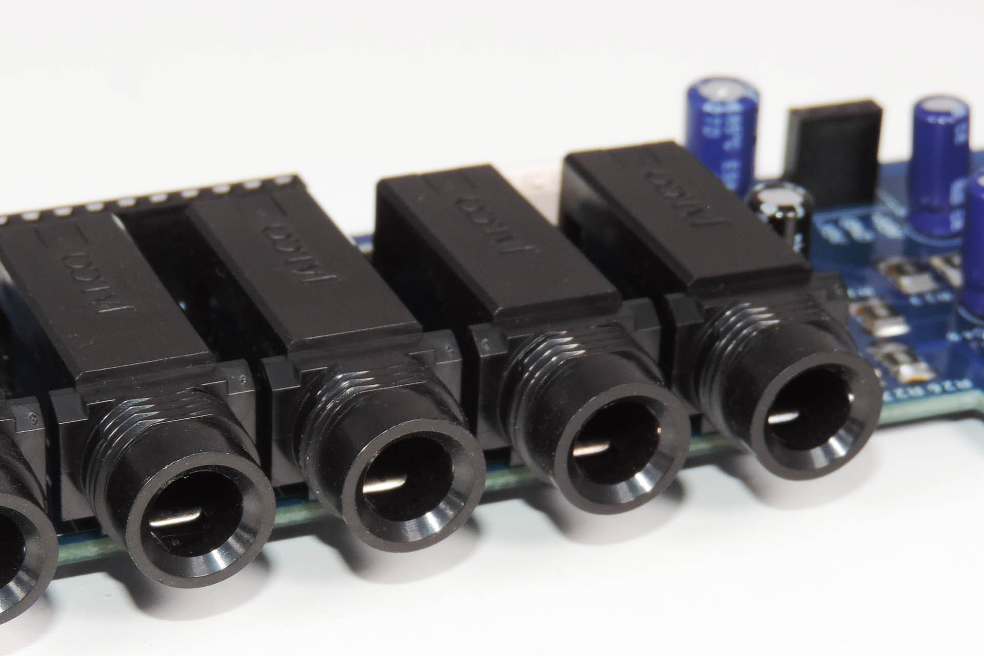
With the exception of the 'total mix' output jack, Nebula's jack sockets are the non-switched 3-pole versions of the original switched mono jack sockets.
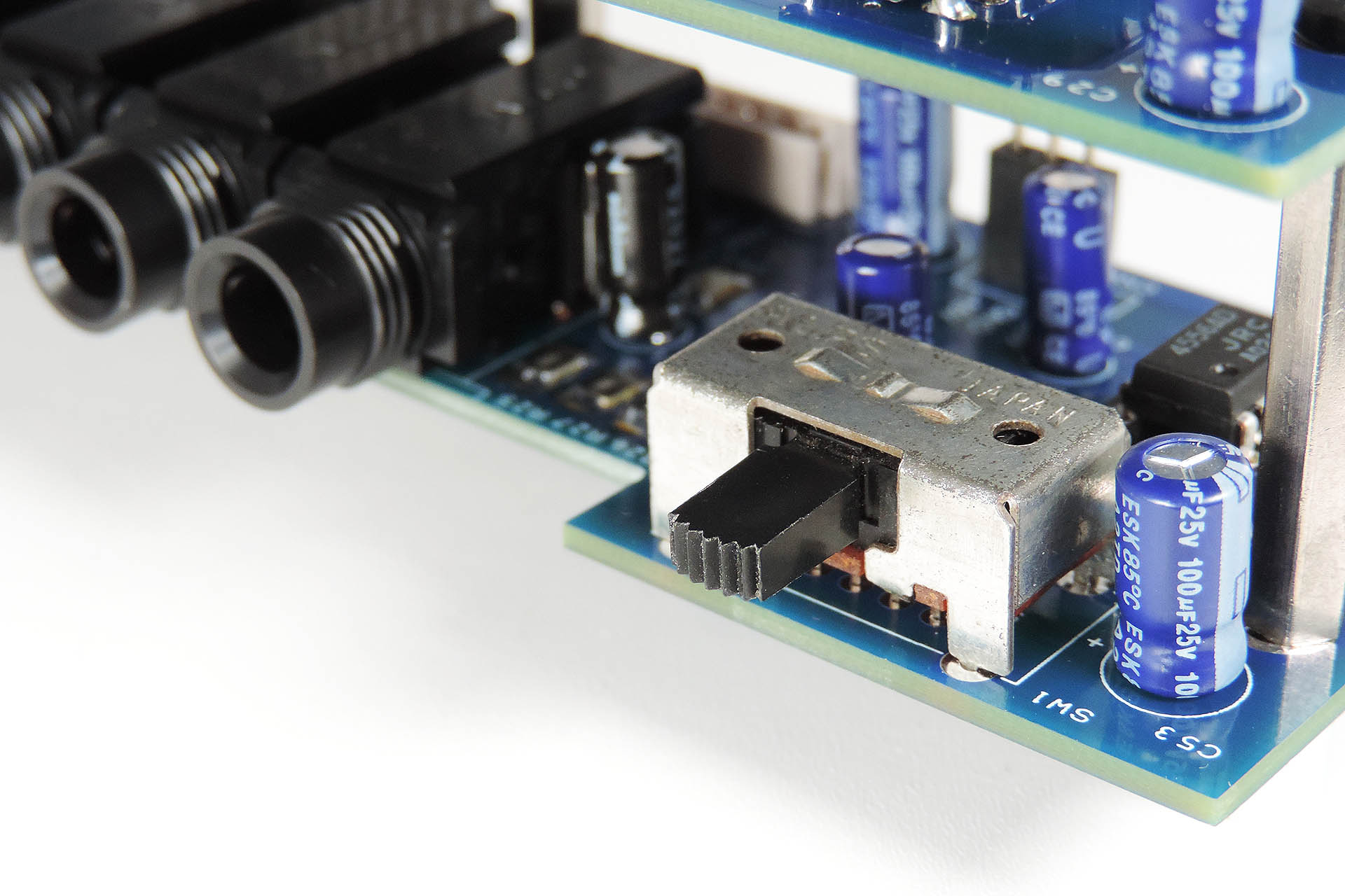
To do the same with 3-pole jacks was impossible as switched, 3-pole jack sockets are just too wide and would not have fitted or lined up with the holes in the rear chassis of the MKS-70. I therefore elected to use a manual mechanism to switch between stereo and individual outputs.
Here's a very early Nebula version which used a DIP switch to engage a couple of relays that change the mode of the outputs from stereo to individual. While functional, I didn't really like this approach.
Accessible through the rectangular hole originally used for the output level selector switch, Nebula’s original design used a DIP switch to engage a pair of relays that changed the output configuration from stereo to individual. While this worked just fine, I then realised that if I used the original output level selector switch to do this job, the back of the MKS-70 would look unchanged. Pretty cool but that meant that Nebula would no longer be ‘plug-and-play’. Hang on a minute… why don’t I provide for both? So, the original versions of Nebula had provisions for either a DIP switch (Nebula DS) or the reuse of the original output level selector switch (Nebula OS).
Nebula original Alps SSP12240A version worked just fine and looked great but required the output level selector switch to be removed from the old Roland jack-board and repurposed. Nebula would no longer be Plug 'n' Play as I originally intended it to be.
Well, I wasn't happy. That switch thing bugged and bugged me. As mentioned, one of the objectives of Nebula was that it should be plug and play with no soldering involved. A medium sized Phillips screwdriver should be the only requirement to fit my new balanced outputs jack-board for the Roland MKS-70.
The problem was that I couldn’t find a right-angle slide switch big enough. Yes, you read correctly; BIG enough.
Modern switches are much smaller than what was used in the eighties and I couldn’t find anything with adequate clearance between the lever and the bottom edge of the slot cut-out on the rear of the MKS-70.
But I persevered, my quest continued and indeed I eventually found a switch which was physically as similar to the original as it was going to get.
And finally... I found a very suitable switch to change Nebula's output mode from stereo to individual.
The first revision of Nebula used 0805 and even 0603 SMD passive components and SMD chips. It took a long time to build the prototype and it was apparent that if I was going to be making a few of these, doing things like this wouldn’t be practical or cost-effective. I therefore redesigned everything with 1210 package SMDs and full-sized DIP ICs. Amazingly, I still managed to get everything to fit on my two PCBs and so, version 2 was born.
I guess I should also mention that version 1 had dual stereo outputs when switched to 'STEREO' mode.
A neat idea but I decided to ditch that one as I needed to be mindful of current consumption.
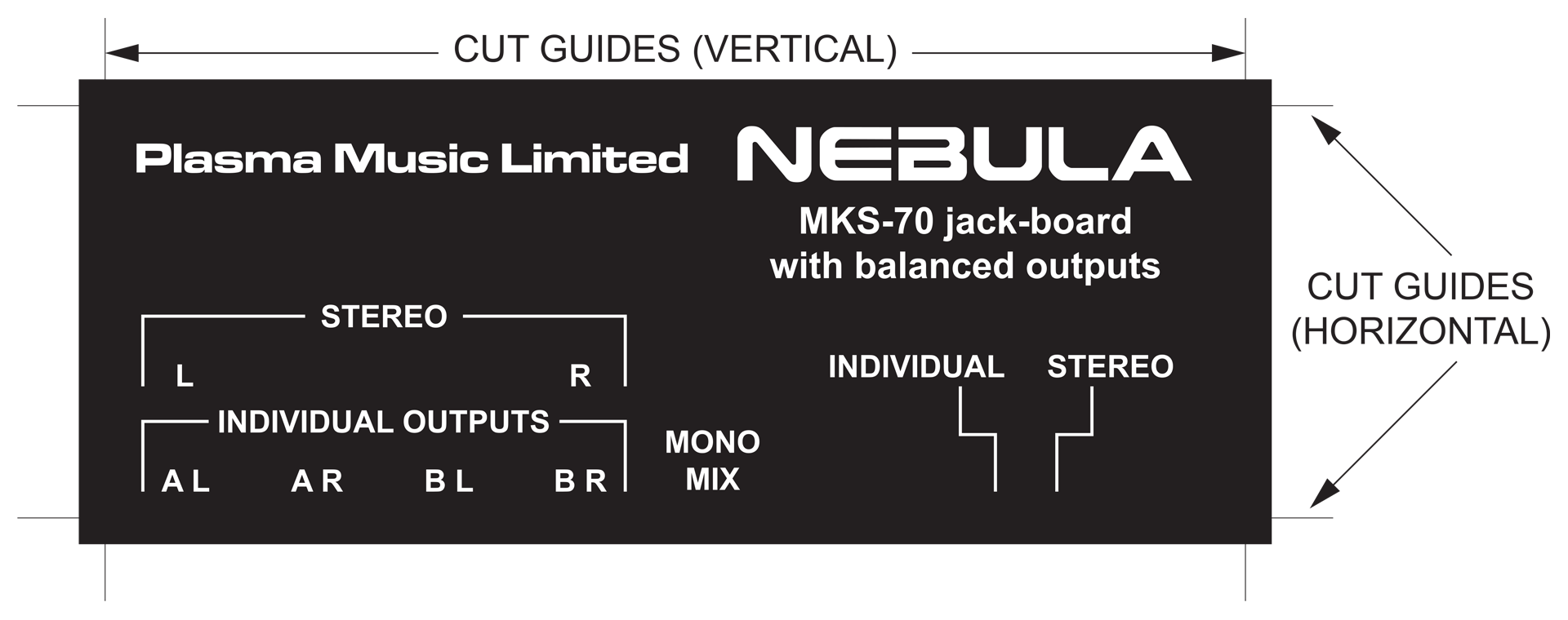
Nebula is supplied with a self adhesive label detailed how to switch between stereo and individual output modes.
Some users get confused about the four outputs on the back of the MKS-70. Well, the MKS-70 has two module-boards and each module-board has two (stereo) outputs. Both pairs of outputs can be mixed so as to provide a simple stereo output from the instrument.
The outputs from each module-board however, can be accessed individually. Some users take advantage of this feature as it's like having two synthesisers and opens up a whole new bunch of possibilities.
Here's a quick reminder of how to connect the outputs from the MKS-70 so as to take advantage of either stereo or individual outputs..
Nebula's current draw from the +5V supply is a little less than the original jack-board as I'm using a SN74HC14 instead of the SN74LS04. More about that later. Apart from the headphone amp, Nebula ended up with an additional eight devices; four op-amps and four balanced line drivers, all pulling an additional +/- 40mA. In separate output mode, the relays kick in to switch routing, increasing current consumption from the +15V line by another 8mA. Even with upgrades like Fred Vecoven's PWM kit however, this won't be a problem but the dual stereo configuration might have been a bit ambitious and with no practical benefit in the real world.
Choosing the op-amps and balanced line output drivers was only a minor challenge as I kind of knew what I was going to use. In fact, I like to think that I got a good balance (pardon the pun) between quality and cost. The fact that the ICs are DIP format means that I could now socket them and this got me to think that people could potentially try their own selection of chips. This was an unexpected bonus to using old-fashioned, full-size DIP ICs, LOL. 😎
The first Nebula had a gain-stage in-between the high impedance input buffers and the balanced line drivers. Like the dual stereo output idea, this also got scrapped but for different reasons; since balanced lines are inherently 6dB hotter than their unbalanced counterparts, more gain wasn’t necessary. Here's a little diagram to show why this is...
Simple Mr. Bond but brilliant.
The other reason was that apart from the headphone amp and hence, the mono-mix output, the outputs on the original jack-board are basically driven from the last op-amp (you guessed it, a M5218) on the respective voice-board. This means that the jack-board itself, doesn’t generate and hence, pass on any noise on to the outputs. As such, any replacement jack-board would have to compete with something that’s dead quiet.
Modern op-amps are VERY quiet but I really didn't see the point of rocking the boat.
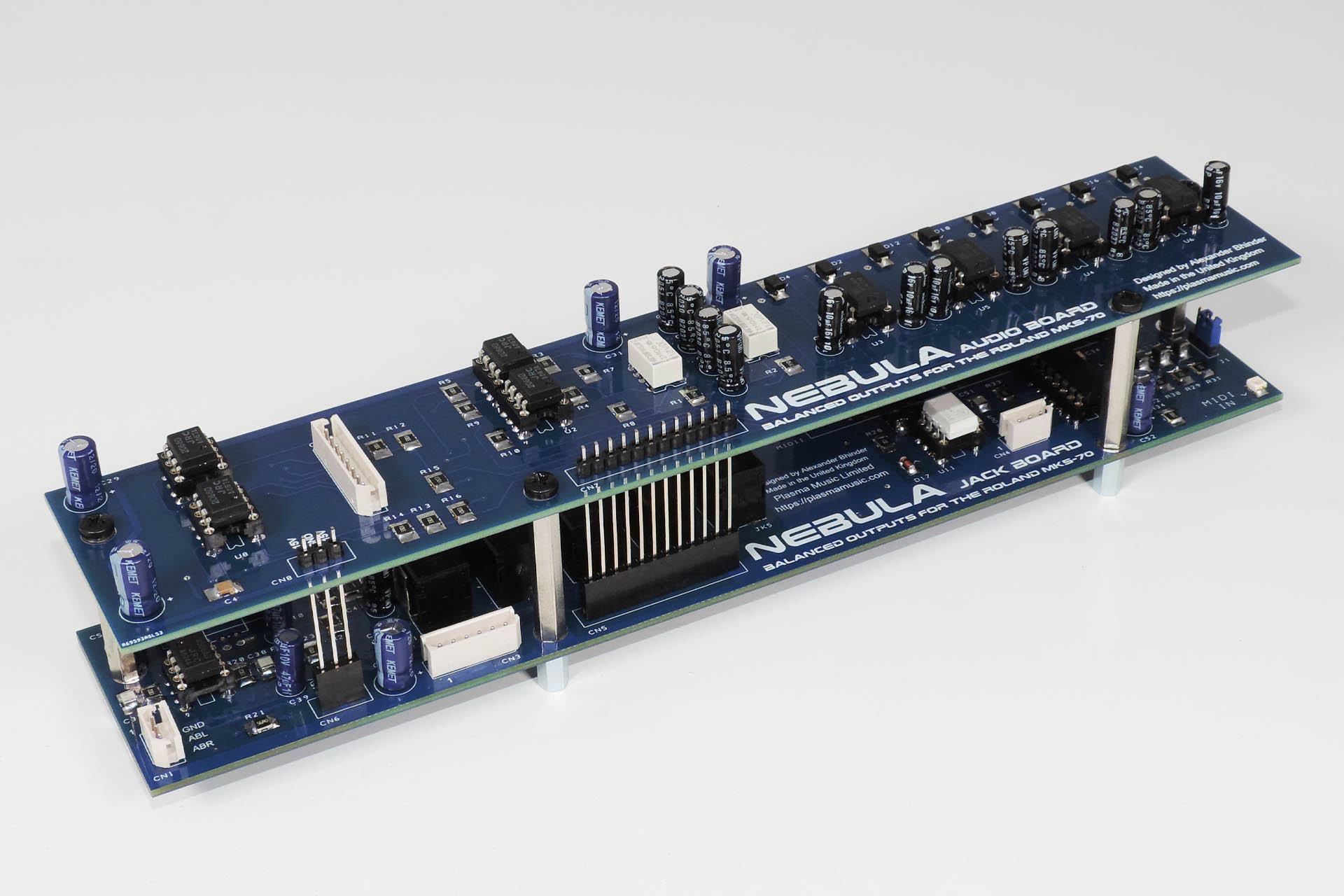
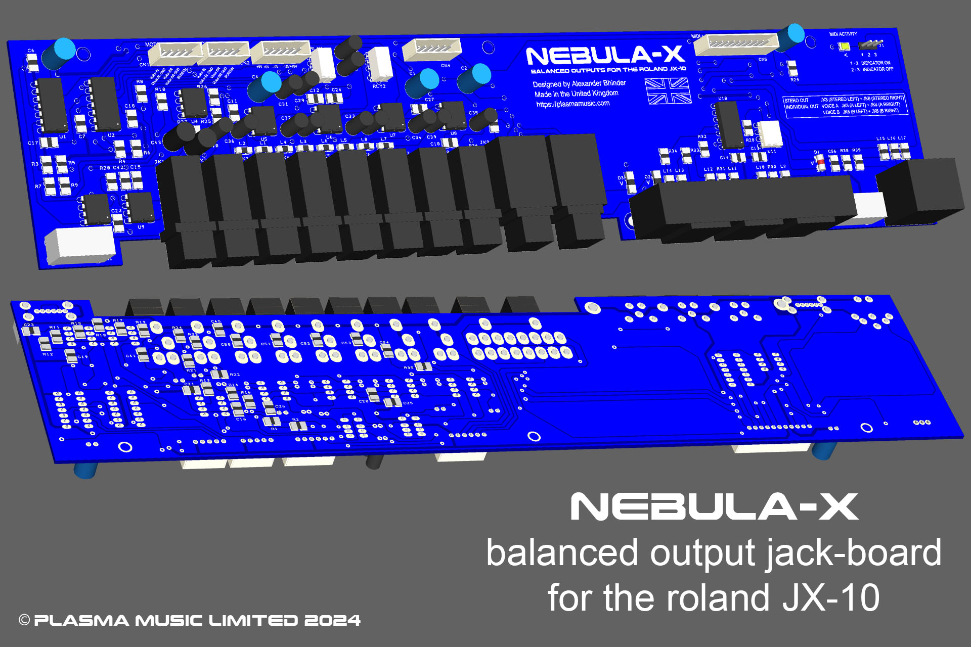
This is a 3D capture of the final versions of Nebula's PCBs, from EasyPC, my design software.
Version 2 therefore, had a simple array of unity gain, non-inverting voltage-followers offering a high impedance to the outputs of the voice-boards and lots of drive for the inputs of the balanced line drivers.
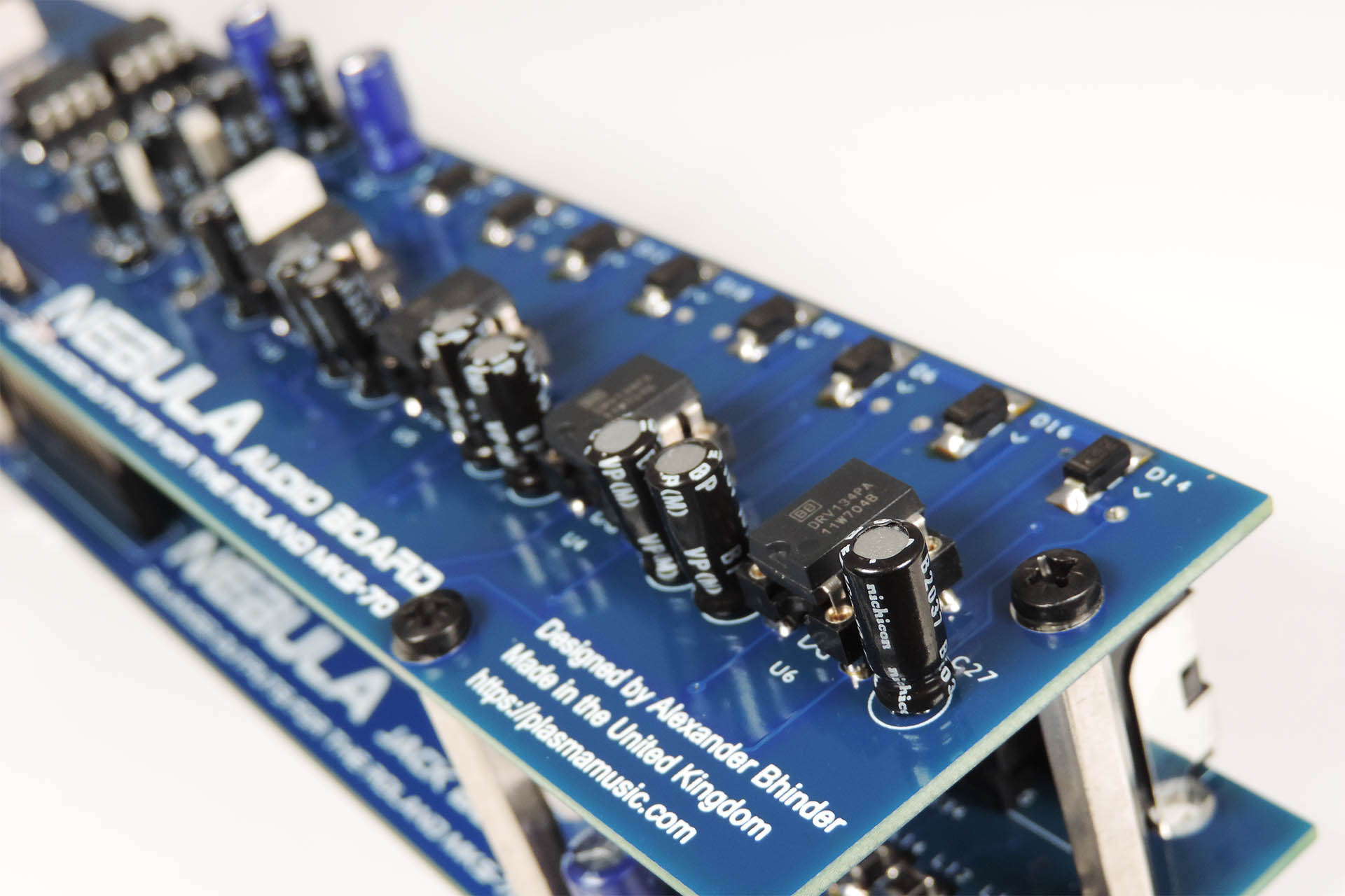
I’ve always used dedicated balanced line drivers such as the SSM-2142 and the THAT-1646, in preference to messing around with various configurations of op-amps. The results are ALWAYS better. This time around, I settled on the Texas Instruments DRV-134. Specification-wise, all these chips are pretty much the same. With the SSM device being long obsolete however, the choice was narrowed down to two.
Delivering superior phase coherency, Nebula uses individual, dedicated balanced line driver ICs to produce balanced outputs of each channel, as opposed to a dual op-amp configuration.
Keeping costs down without sacrificing performance or quality is a challenge common to any design process. With negligible technical differences between the THAT-1646 and the TI DRV-134, I'm not ashamed to admit that the decision to use the latter, was based solely on cost. Having said that, if for whatever reason, you want to swap out the DRV-134s for the THAT-1646s, or even SSM-2142s if you still have some, you’re more than welcome to do so. The devices are all pin-for-pin compatible.
Balanced line driver ICs are NOT op-amps! Indeed it should be noted that one of the crucial differences is their input impedance which in the case of the DRV-134, is a mere 10kΩ, much, much lower than an op-amp. The other devices I mentioned have similar input impedances. Dealing with low input impedance devices, was another reason I was reluctant to design a passive array (similar to what Roland did) and hence, implemented the previously mentioned unity gain, non-inverting voltage-followers, to go in between the outputs of the voice-boards and DRV-134s.
I've designed a lot of balanced output stages over the years and in my experience, using dedicated devices like the DRV134 always delivers accurate, high quality results.
Like all the stuff I design, Nebula includes a few extras and so incorporates the following refinements:
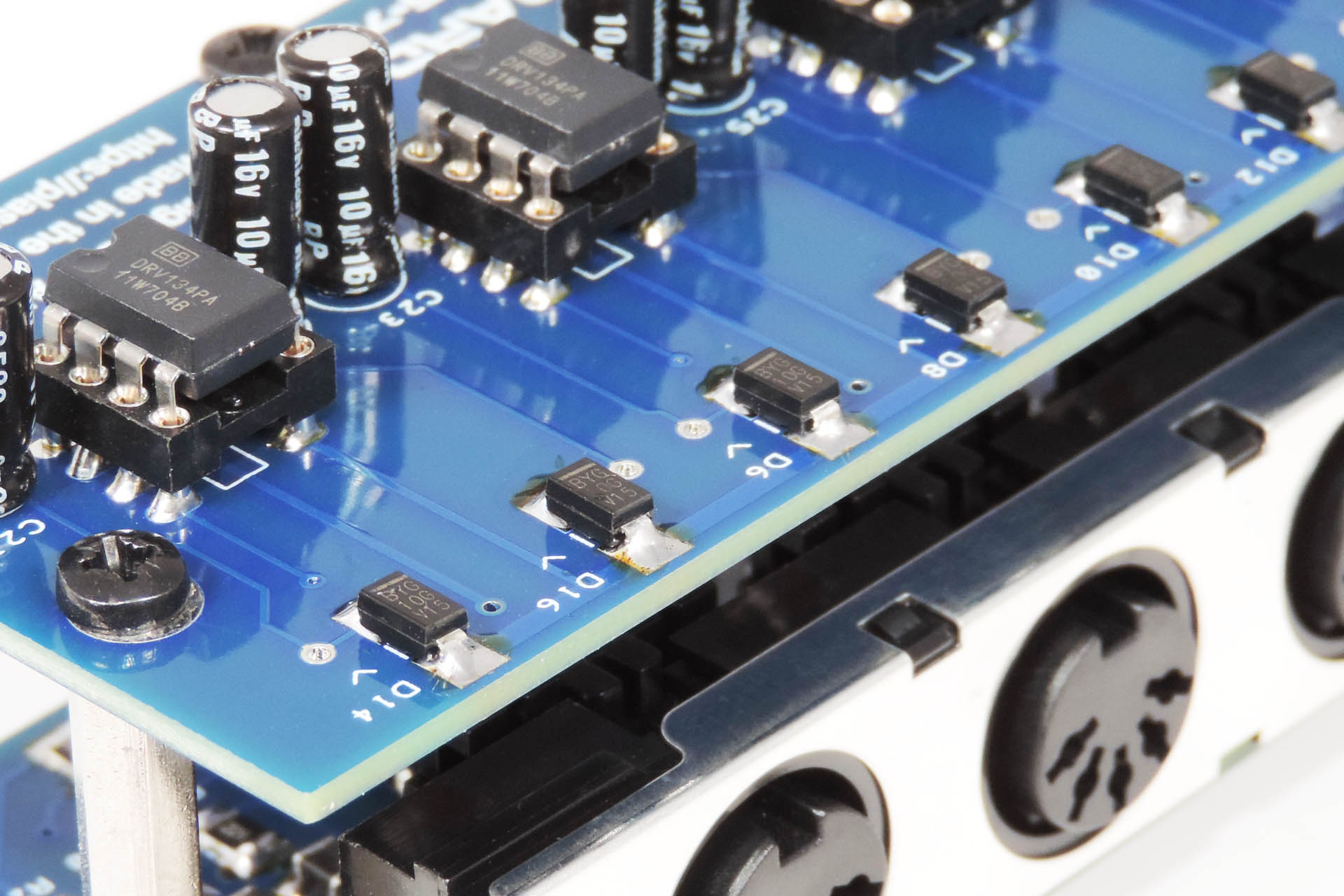
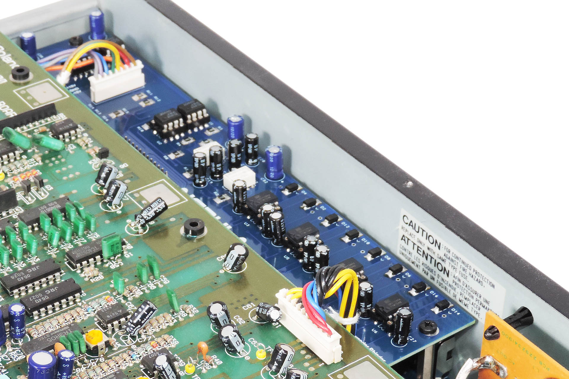
diodes on all output phases to protect against high capacitance loads and phantom power (we’ve all done it),
ferrite bead / capacitor filter network on each phase of each output to reduce the effects of RFI / EMI.
Capacitors on ‘SENS’ outputs of balanced line drivers to mitigate effects of dc offsets on outputs.
These refinements have nothing to do with balancing the signal. They're included so as to ensure that the output of your MKS-70, is as clean and as noise-free as possible and that they're protected against bad things from the outside world!
Nebula has RFI / EMI filtering and diode protection (pictured) on all output phases.
Some will argue the point of implementing the above in favour of cost but to be honest, I just wouldn’t have been happy had I missed all of that out. At the end of the day, Nebula does make the MKS-70 sound better!
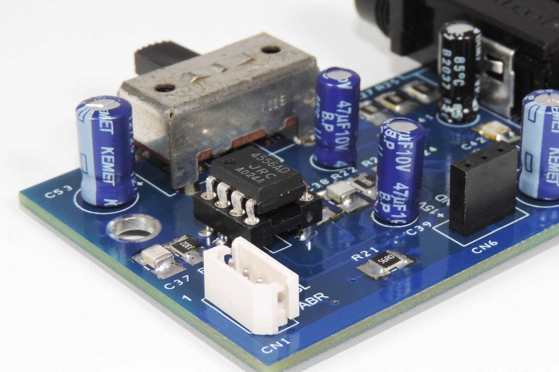
Nebula retains a driver IC for the front-panel headphone output but it’s been upgraded from the original M5218L, to one of my favourite ICs for headphone amp applications, the NJM-4556AD. Like the NJM-2068D that I used for the buffers, the 4556 is a well spec’d dual op-amp but, it’s also particularly good at driving high-reactance loads… like headphones.
Nebula uses the NJM4556 for the headphone amp as it's great for driving high reactance loads... like headphones.
Having worked for Simmons and Roland back in the eighties and having designed a lot of audio equipment over the decades, I didn’t doubt that Nebula’s audio and MIDI wouldn’t work. I was however concerned about how the MKS-70’s CPU would respond to the changes.
Nebula has upgraded MIDI as well as balanced outputs.
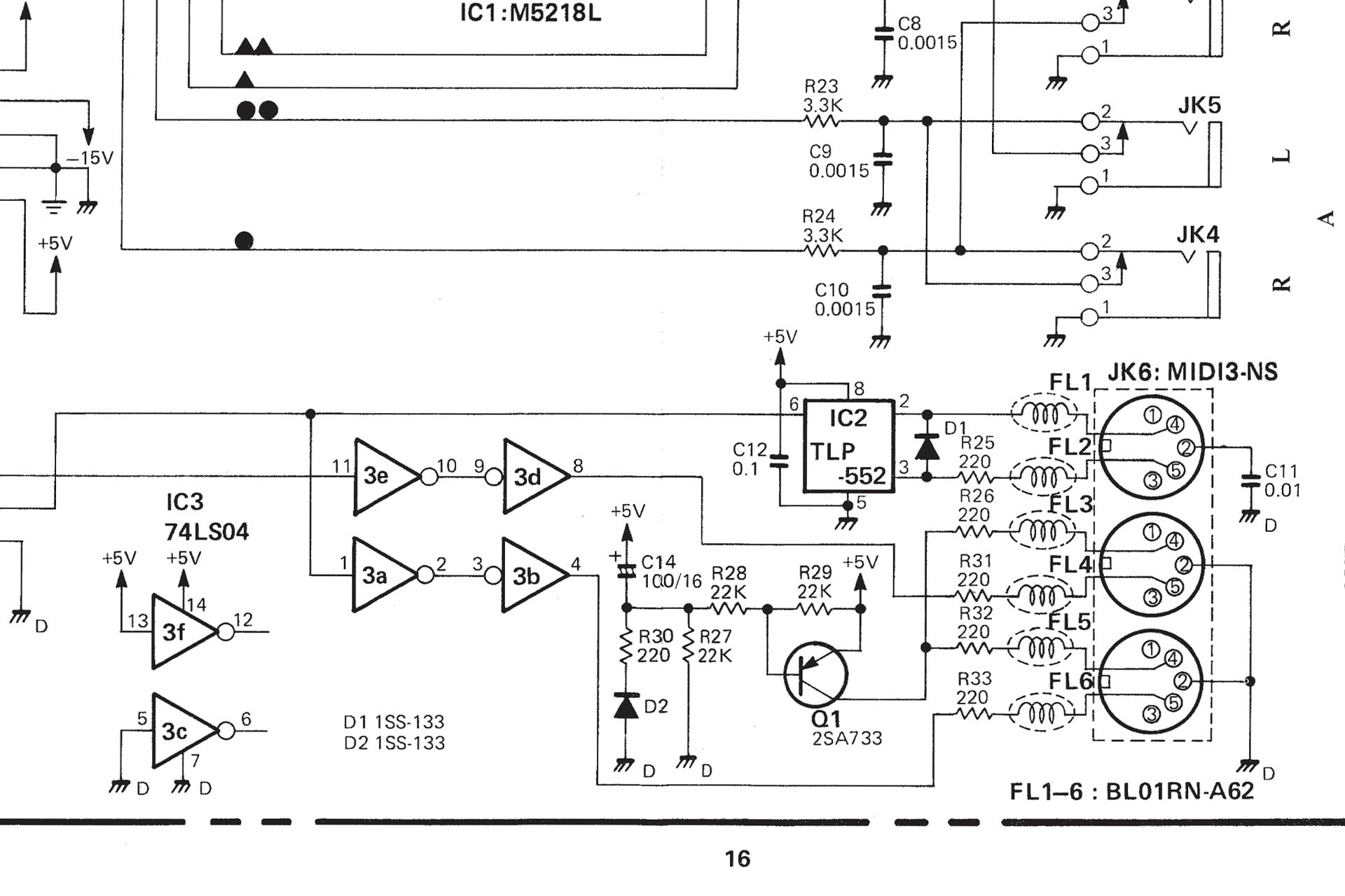
Roland used the TLP-552 CMOS opto-isolator in the MKS-70's MIDI circuit, which was much faster than devices like the standard and very popular Sharp PC-900 which also had a Darlington output. I looked carefully at a variety of modern equivalents and came back to my favourite MIDI opto-isolator; the 6N137.
The opto-isolator on Nebula is the 6N137, one of my favourite devices for this kind of stuff.
The 6N137 is faster, more accurate and has better output drive than devices such as the 6N138 meaning that for an ol’ girl like the MKS-70, it’s absolutely ideal.
Similarly, I substituted the SN74LS04 hex inverter, with a 74HC14. Apart from being a low-power device (HC), the 74HC14 has Schmitt trigger inputs, meaning that the output of each stage, only switches between states (0V and 5V or logic '0' and logic '1'), when the inputs cross a specific threshold. Theoretically, this makes the MIDI circuit less likely to pass spurious voltages on to the processor.
Well, I’m pleased to confirm that after extensive testing, Nebula’s MIDI circuit works just perfectly, supplying a much ‘cleaner’ MIDI signal to the CPU. In fact, your MKS-70 will love it! 😊
Oh, by the way, since MIDI OUT also passes through two inverters of the 74HC14, the advantage works both ways, meaning that the MIDI data stream leaving your MKS-70 will be, well... squarer!
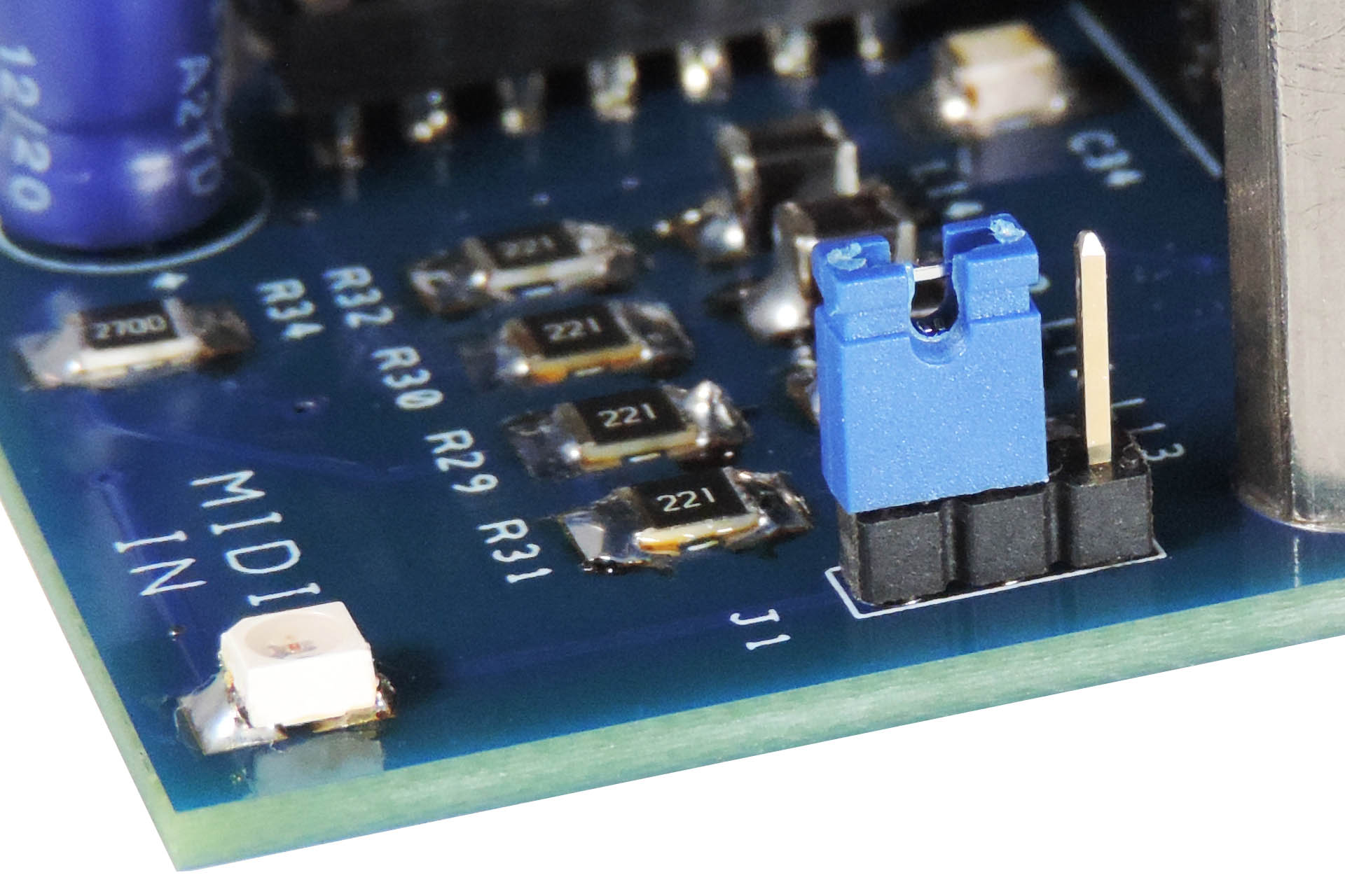
As per the original circuit, All MIDI lines are fitted with ferrite beads, again to reduce the effects of RFI / EMI.
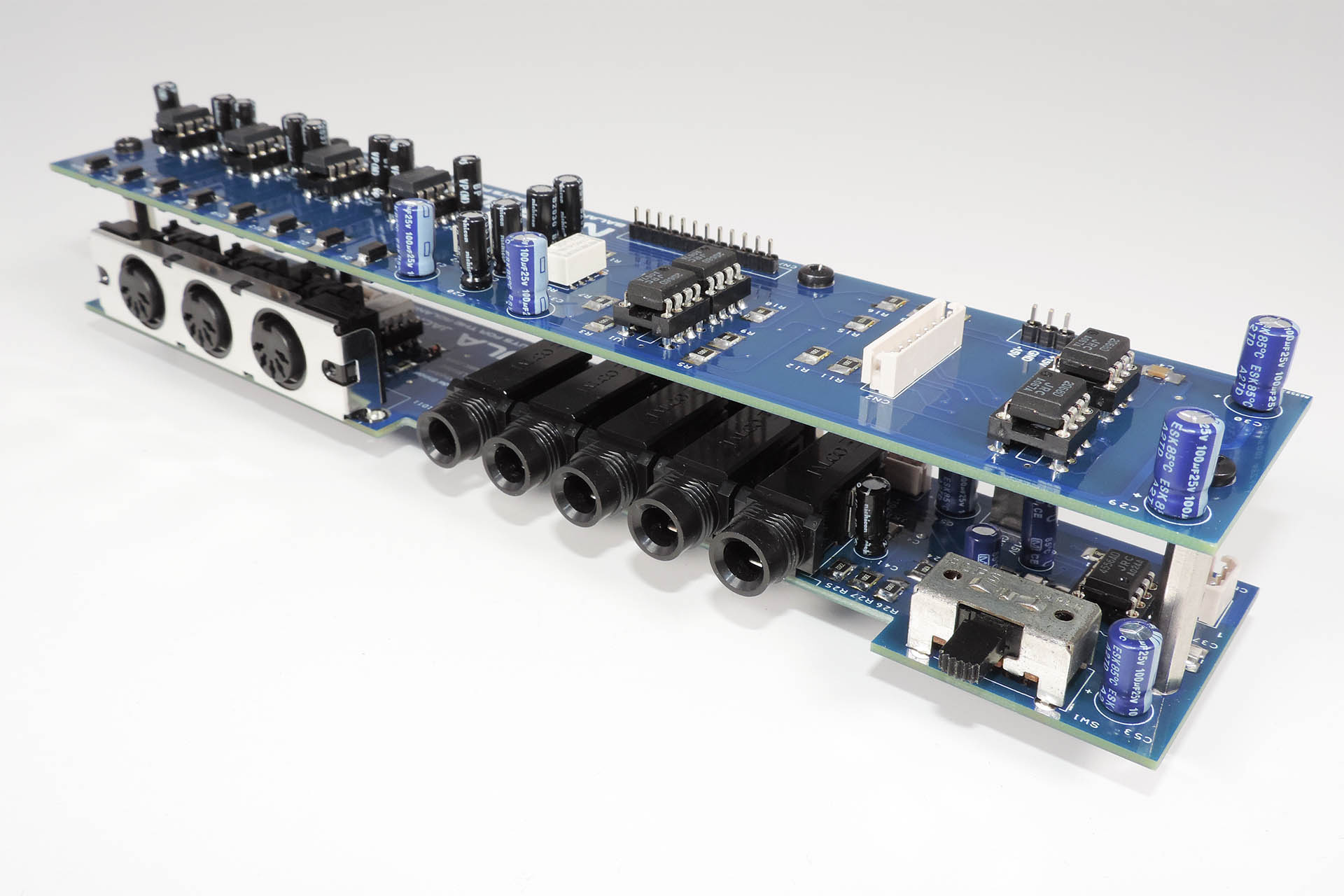
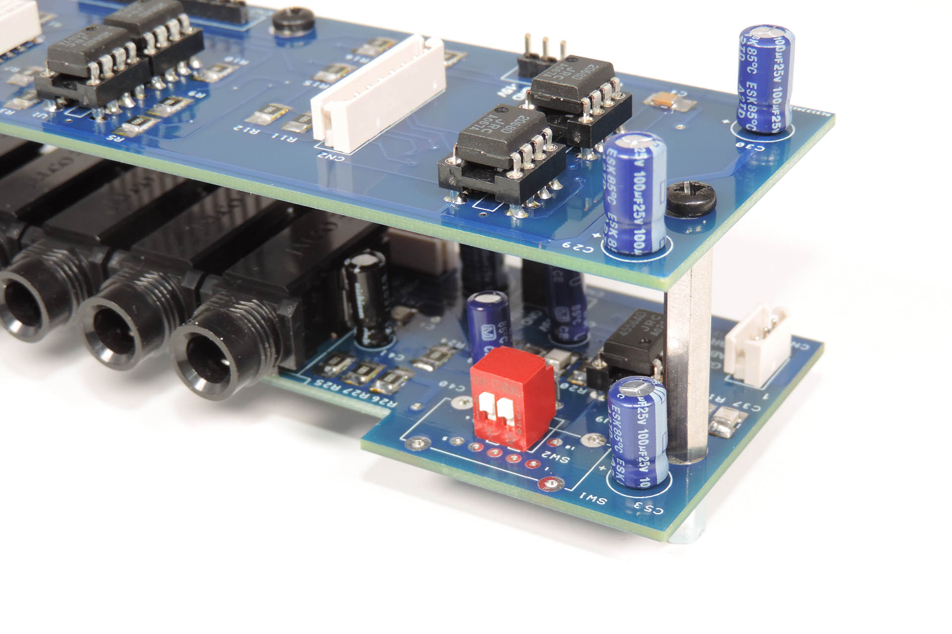
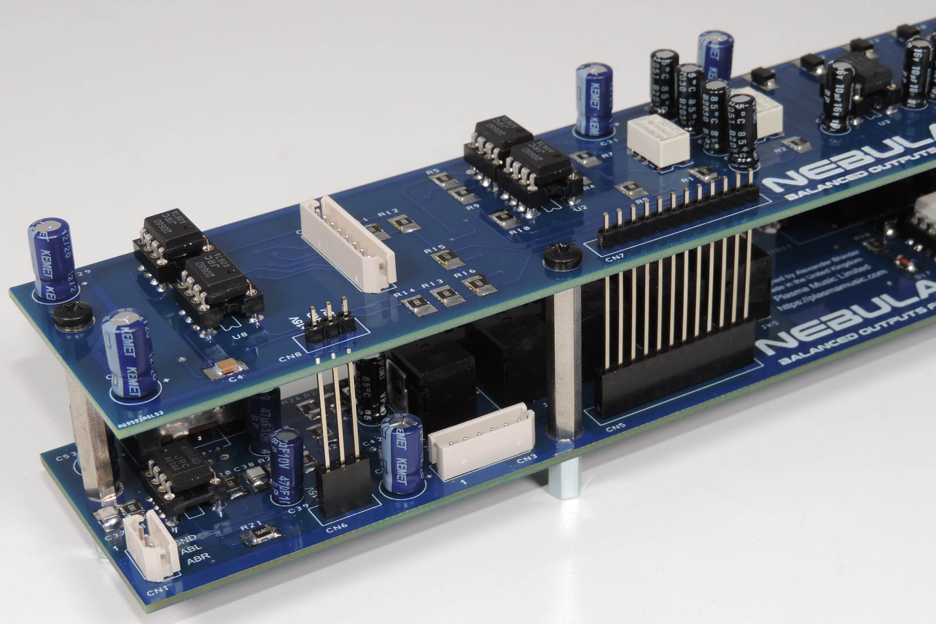
Nebula comprises two PCBs; the top (audio) PCB has the main audio components on it and the bottom (jack) PCB has the headphone amp, audio jacks, MIDI sockets, selector switch and MIDI circuitry.
Nebula has two tiers; one for audio and one for MIDI, sockets and headphone amp.
A couple of otherwise redundant inverter stages on the 74HC14, are used to drive a conveniently placed LED, which is used as a MIDI status indicator. With the lid off your MKS-70, you can easily check to see if MIDI data is coming into the unit. Please note however, that all MIDI data will trigger the LED, including clock and active sensing, as there's no filtering here, it's just raw MIDI data.
If you find it distracting, a jumper next to the LED, allows you to turn it off.
Nebula's MIDI status LED can be turned on and off via a simple 3-way header / jumper.
The DIP switch (DS) version of Nebula is plug-and-play and if you really want to keep the back of your MKS-70 looking factory, then transplanting the output level selector switch makes Nebula virtually plug-and-play. The positions of the headers connecting the original jack-board to the rest of the MKS-70, have been respected and it’s only the audio connection from the MKS-70 voice-boards that is slightly different, being on the top (audio) board. This means that there's no need to mess with Roland's impeccable wiring loom! 🙂
Nebula installs quickly and easily with headers all in the right place for the internal cables.
To ensure the best visibility and accessibility, I thoroughly recommend that the MKS-70 voice-boards be removed prior to fitting Nebula. I should also point out that there's only a couple of millimetres clearance between the voice-boards and Nebula's double-decker PCBs, so trying to fit Nebula with the voice-boards in place... well, Nah!
Nebula is supplied assembled and the top and bottom boards need to be separated prior to installation. With a gentle pull, Nebula’s boards easily come apart, allowing the jack-board to be lined up and secured as per the original.
I personally found that after removing the metal jack socket retention plate from the original jack-board and fitting it to Nebula’s jack-board, lining up the sockets with the holes in the MKS-70 rear panel and then loosely screwing the jack-board to the four internal posts using the supplied 30mm PSB spacers, followed by gently securing the external screws, was the most reliable method of installing Nebula.
Original MKS-70 jack-board showing jack socket retention plate.
One last point on assembly; unless you have plans to send your MKS-70 on a deep space mission out of the solar system, please, please, please DON'T OVER-TIGHTEN the screws!
The multi-pin connections between Nebula’s boards are soldered with the boards in place and should therefore line up nicely, after the 30mm PCB spacers are fitted to the jack-board. Once secured, just make a final check to see that all twelve pins of CN7 and all three pins of CN8 are properly mated with CN5 and CN6, respectfully, prior to securing the audio-board with the four screws.
Nebula's inter-board connectors are soldered with boards in place to ensure perfect alignment.
So, once I finally got things to fit properly, I was actually really excited about Nebula balanced outputs jack-board for the MKS-70 and to be honest, I found it a bit difficult to keep quiet. In fact, I couldn’t help myself and let slip to some of my regular customers. Oh boy… I couldn’t believe the response and although Nebula hadn’t even been built, let alone properly tested, suddenly I had a small backlog of orders. Thanks for the vote of confidence, guys but seriously?!!?!
Although I have recently found new premises for Plasma, following last year’s flood, I’m still working at home with limited access to my ‘usual’ equipment and so the development of Nebula balanced outputs for the Roland MKS-70 had other, indirect challenges. It was however, a fun little project and I’m so pleased that it all worked. Yes, I wasted a little time and money on getting things to line up and fit properly but I knew what I was letting myself in for. Once the version 2 prototype with DIP package ICs was built however, it was truly rewarding to see it all come to life.
A nice snug fit, Nebula kind of looks like it belongs, like it's always been there.
I have now installed Nebula in two of my three MKS-70s and at the time of writing, Nebula is also working perfectly in two customer units (thanks Jason and Chris). One more installation and that’s my first batch gone! 😊
To conclude, here’s what Nebula offers:
Plug 'n' Play installation only requiring a Phillips screwdriver and a little patience
6dB hotter signals than unbalanced outputs
Increased immunity to external noise
Better signal-to-noise ratio
Greater dynamic range
Reduced crosstalk between left and right channels
Reduced crosstalk between module-boards
More powerful and cleaner headphone sound
Increased MIDI stability
Nebula is available for purchase here:
Nebula won't change the sound or character of your MKS-70. It'll just give you a cleaner and louder signal at your desk.
UPDATE - 19th August 2021
I'm always reluctant to just post my stuff (like Nebula) on social media groups as I respect the rules which often include restricting self promotion and sales, for example. I will therefore endeavour to contact one of the administrators to ask their permission to do so. On this occasion, however, I feel rather humbled that Keith Meiere, admin' of the Roland JX-10 and MKS-70 Synthesizers Facebook group, put up a post featuring Nebula, before I'd even approached him. Thank you so much, Keith.
People have commented on the idea of a version of Nebula for the JX-10. Yeah, I forgot to mention that. Of course designing something like Nebula, you kind of think that you're doing so for two machines; the MKS-70 and... the JX-10. The problem is that the JX-10's jack-board is really quite different to that in the MKS-70. Being a performance keyboard, it has a load more sockets than it's rack-mount cousin. On top of that I don't have a JX-10! 🙁 but... let me think about it...
UPDATE - 17th October 2021
Firstly, I'm pleased to announce that detailed and illustrated installation instructions for Nebula are now available for download after purchase.
Secondly, many thanks to Chad Kainz for his lovely write-up, detailing his Nebula installation. You can read all about his ex-Thomas Dolby MKS-70, how he did it and check out his brilliant photos, here.
Thanks Chad. 'Makes me feel very humble.
UPDATE - 5th October 2022
I love it when people send me interesting questions and today I received an e-mail asking if Nebula would help reduce crosstalk between the MKS-70's outputs. The answer is YES but you can read all about why and how here. 😎
UPDATE - 15th November 2023
I'm very lucky to have such awesome customers and occasionally, I get some feedback which makes my day. 'Rob H' recently contacted me and here's an extract from his message:
"Love the new output board for the MKS-70, btw. I installed it a few weeks back, and it really improved the overall quality of the sound."
UPDATE - 19th January 2024
My new screened audio cables for the Roland MKS-70, improve the signal quality going into Nebula.
Giving the Roland MKS-70 balanced outputs improves noise rejection between the MKS-70 and the destination device, improving overall sound quality. Nebula can't do anything about noise picked up between the outputs of the module-boards and its inputs.
To improve the quality of the signals going into Nebula, I therefore designed a pair of screened audio cables which do indeed reduce the noise picked up from within the MKS-70. You can read all about them here.
My screened audio cables for the Roland MKS-70 are now offered as an option when you purchase Nebula.
UPDATE - 22nd March 2024
Nebula is one of the least cost-effective things I make. High quality components and very labour intensive, I simply can't charge for the actual time it costs to make. Luckily, I love what I do and when I receive e-mails like this, it makes it all worthwhile.
"Thank you - label received! Also, I installed Nebula last week with no issues and it works fantastic! Very happy that my MKS70 is louder and clearer now - so much more useable, like a new synth!
Many thanks;
Matthew " ❤️
UPDATE - 21st April 2024
Almost as soon as I announced Nebula, people were asking if I was going to develop a balanced outputs jack-board for the Roland JX-10. I seriously considered the idea but there were just too many complications, unique to the JX-10.
For a start, the JX-10 is a performance instrument so it has a mired of sockets on the back panel, all of which are mounted on the jack-board and many of which are excluded from the studio version of the machine, the MKS-70. Apart from overcoming various technical problems, keeping cost down would be a big challenge.
Secondly, the programmer port is also mounted on the jack-board. Indeed, with the exception of the data cartridge, anything you can connect to a JX-10, is done so via the jack-board.
While the assigner-board and module-boards in the JX-10 and the MKS-70 are identical, the jack-boards are very different indeed with the former being considerably more involved.
Anyway, incorporated into the Nebula-X design, are a couple of cool tricks which I've used before, specifically to combat noise. Perhaps a bit too much to go into any depth here but of course when Nebula-X is released, you'll be able read all about it!
What I will tell you, is that just like Nebula for the MKS-70, Nebula-X uses the same balanced line driver ICs and also has upgraded MIDI circuitry which includes an on-board MIDI activity indicator.
Stay tuned, Super-JX fans! 😎
UPDATE - 29th January 2026
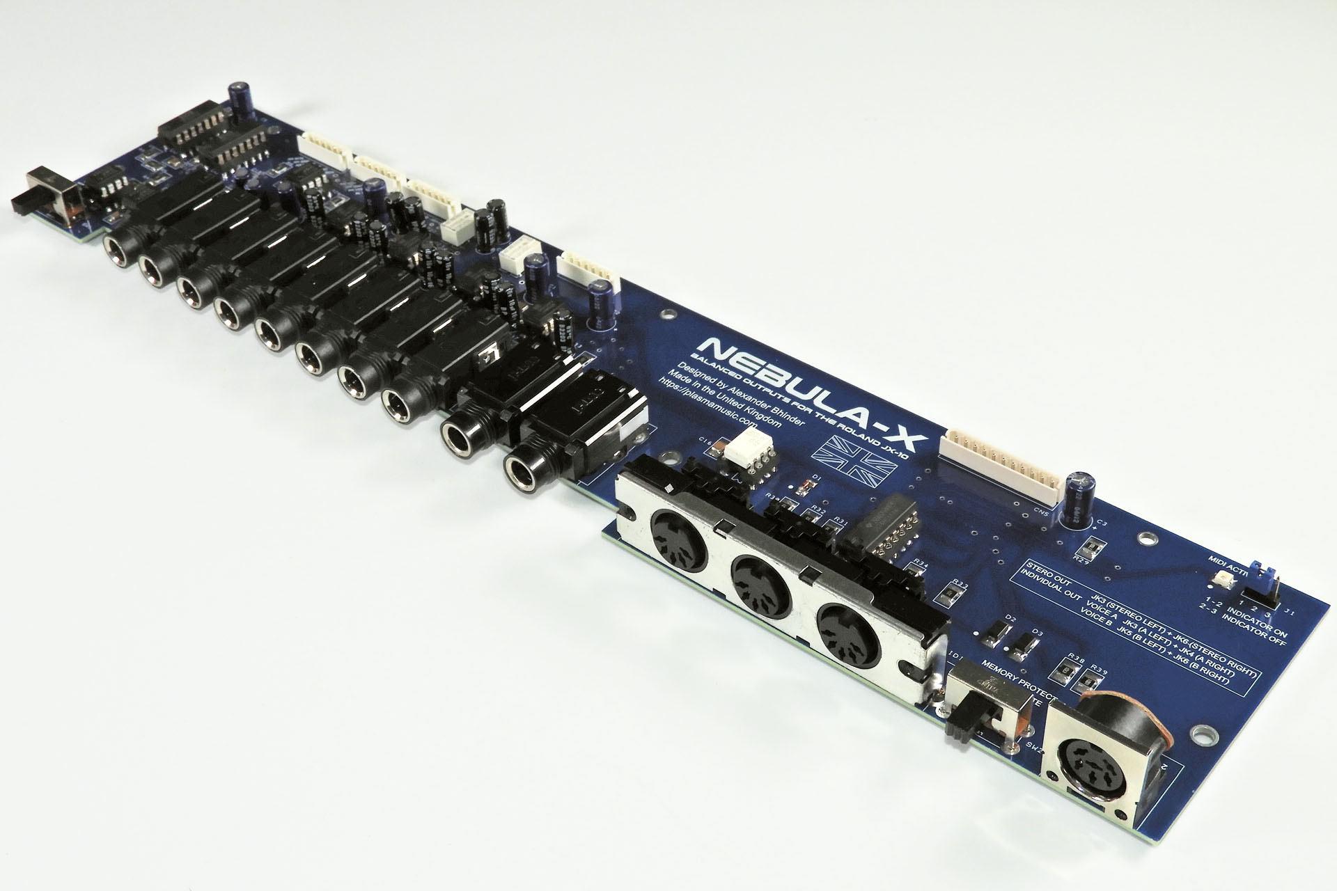
Nebula-X balanced outputs for the Roland JX-10 is finally here!! YAY!!!! 😂
I can't believe it's coming up to two years since my post announcing Nebula-X. Where has that time gone? Anyway, one of my Christmas 2025 projects was to get this damn thing done. Most of this month has been testing Nebula-X and I'm absolutely delighted with the results.
You can read all about Nebula-X balanced outputs for the Roland JX-10 here.
I'm deeply concerned about the environment and the exploitation of labour and so I always use local manufacturers in preference to the Far East, with the following in mind:
I can be confident that workers are treated fairly and earn a proper wage.
I can be confident of the standard of quality of each item that is delivered to me.
Communication is important and using local manufacturers, all correspondence is quick and understandable.
I believe in supporting the local economy.
I can be confident that the disposal of manufacturing waste is managed properly and in accordance with national and EU law.
Using local manufacturers isn’t the cheapest option but the above points are important to me. I hope that they’re important to you too.
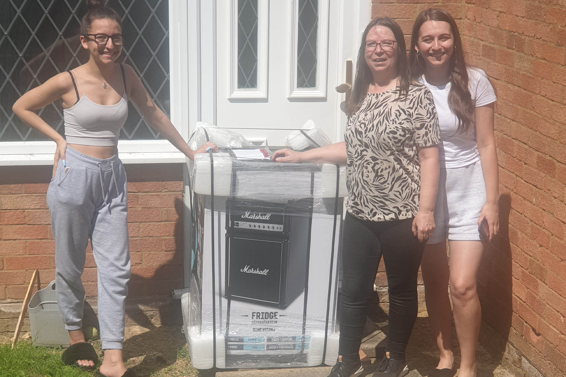
Yesterday, 4th August, was my birthday. My youngest daughter Tsunami has moved back home after finishing university and my eldest daughter Katana, kindly came down from Manchester for a few days.
Soon after breakfast, the girls disappeared only to call me to the house that will be the location of the new studio.
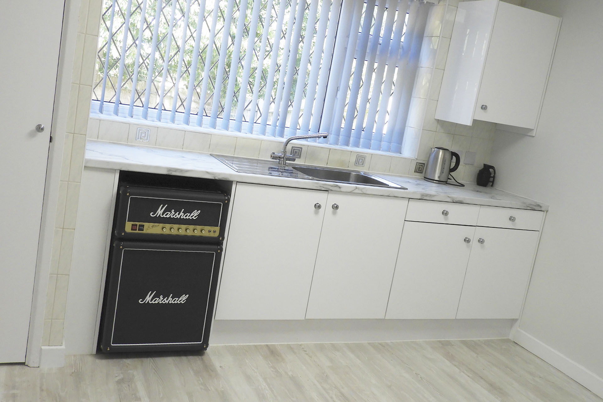
Seriously?!?!?!? A frigin' Marshall fridge!!!! OMG!!! 😀
The kitchen at the new place has been ripped out and the kitchen / diner is being prepared for something a little more streamlined and efficient, let's say. Now I can't wait to get things finished so I can install my new appliance. 🙂
As if that wasn't enough, when we got back home, amongst the lovely cards from friends and family that were on the coffee table in the lounge, was what appeared to be a picture all wrapped up.
I opened it and got the chock of my life! My wife Julie had commissioned my good friend and excellent artist to paint this:
It's a million times more amazing in the flesh and I'd just like to thank Tony and Julie for getting together and delivering this magnificent piece of art.
Thank you Julie, Katana and Tsunami for making this the best birthday ever! 🙂
UPDATE - 17th February 2022
The kitchen was completed in the New Year and the fridge, which is now full of Becks and Pepsi, looks like it just belongs.