It's already been a busy MKS Winter 2023 as for some crazy reason, I'm getting a lot of MKS-70s and MKS-80s in at the moment. Hey, my favourite synths but seriously?!?!?
Yes, I love 'em. I know them really well but still relish the challenges that they throw at me. Some of those pictured above are from overseas which makes me feel quite humbled to have that kind of reputation.
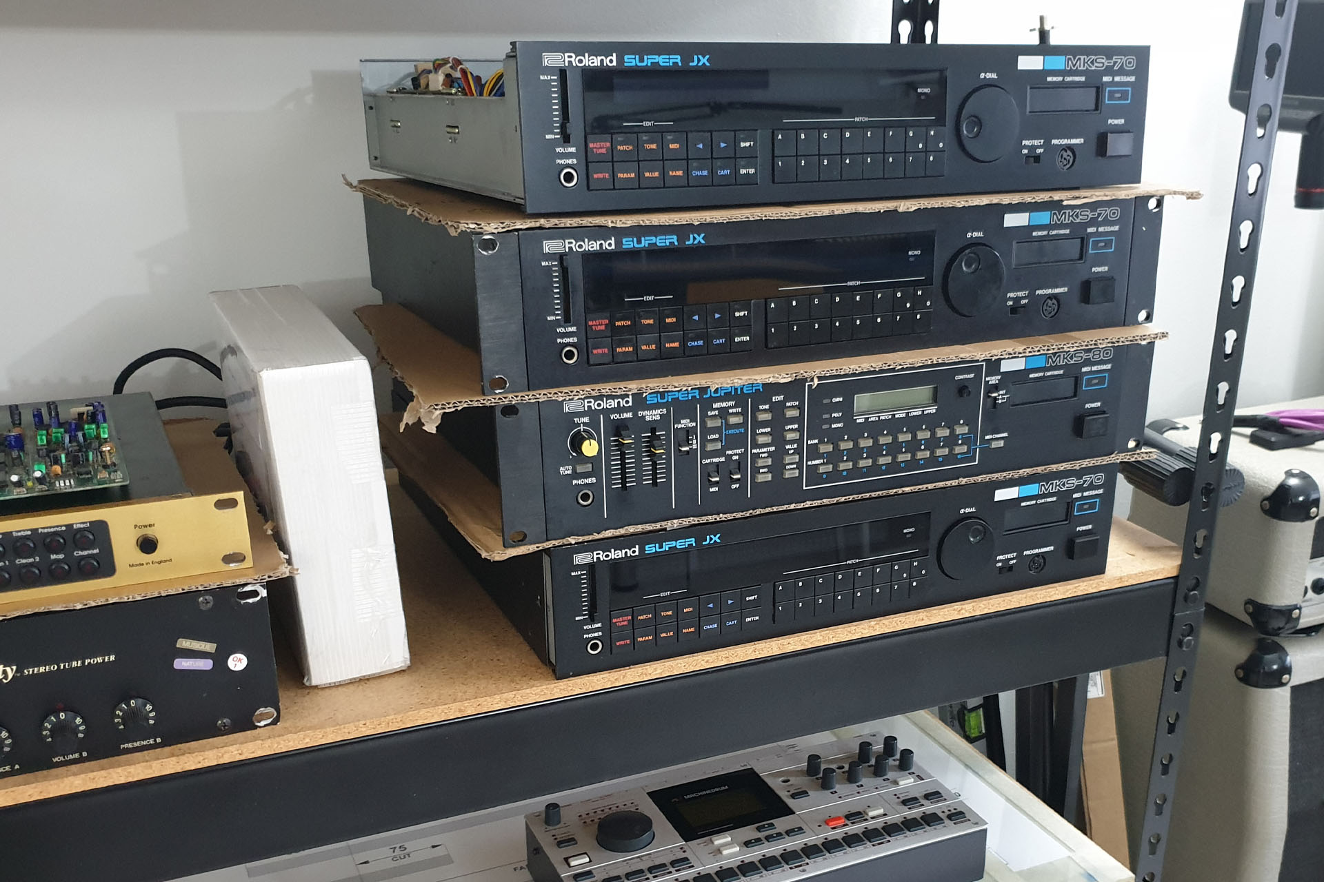
For those interested and starting from the top...
Roland MKS-70 requiring full service and ALL upgrades.
Roland MKS-70 that needed a new power supply (like Guy Wilkinson’s P0004) and replacement front panel switches.
Roland MKS-80 which had two duff voices. The customer also wanted Aurora replacement modular switched-mode power supply installed.
Roland MKS-70 with a serious CPU-board issue (which might take me a while).
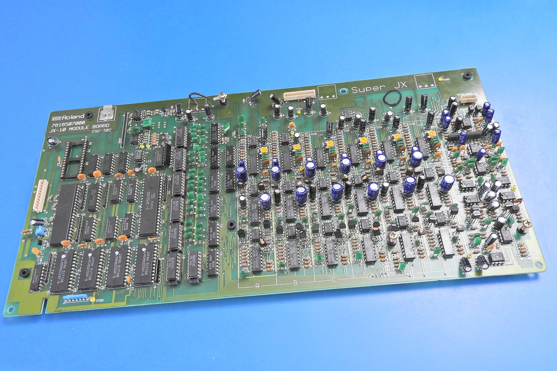
The JX-10 module-board just caught to the left of the picture above but fully shown below, has been sent from a local (UK) customer and has some serious audio issues.
It's funny how things go from amps to synths, then back to amps with the odd 59kg piano thrown in there somewhere! 😀
Almost up to date, I've had a lot of orders for AT-D-50, AT-JX-8P, AT-AJ-2 and AT-JX-10 replacement aftertouch sensors, as well as other stuff and a busy MKS Winter 2023 has got me working all hours, right now.
Search for Plasma Music Limited or just hit the link above.
A couple of weeks ago, I insanely agreed to take on this Roland HP-3700 keyboard service job. “A couple of duff keys” I thought. “Hey, no problem” I thought. Well, I use the word ‘insanely’ because I’d forgotten just how big and heavy these things are. Last time I saw one of these was about fifteen years ago and you know how sometimes your memory of the size of things is just WRONG? Well, this was a good example of just that.
Anyway, I only got around to working on this a few days ago. One problem with getting old, is that our parents are getting older and there comes a point when those who sacrificed so much and looked after us, now need a little attention themselves. Hence, I feel as though I have two jobs at the moment.
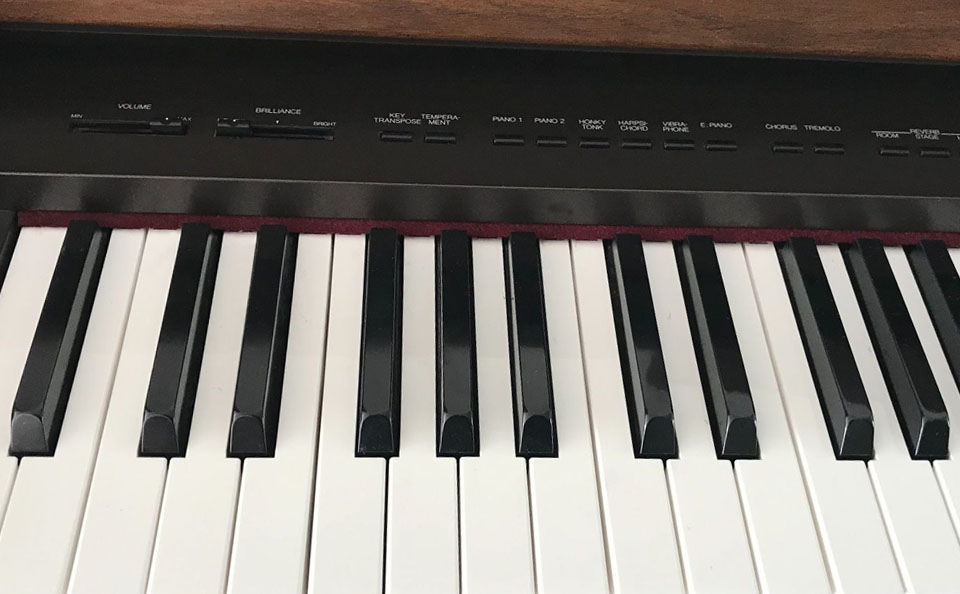
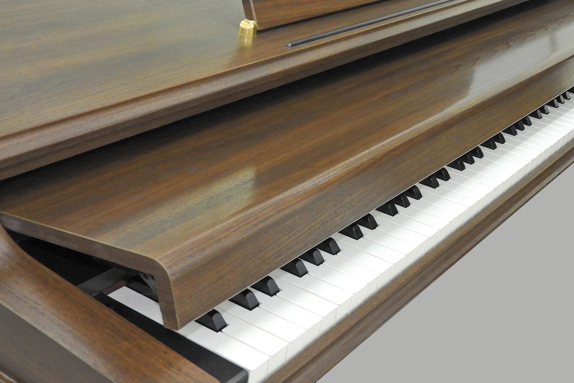
The HP-3700 was launched in 1990. A stunning example of Roland’s precision engineering, beautiful craftsmanship and a level of sonic excellence we take for granted with the name 'Roland', the HP-3700 was indeed the company's flagship full-sized piano a the time. Anyone who’s had experience with one of these instruments, will appreciate that it’s not just about the sound. As I often comment, the smooth, transparent connection between your fingers and the sound, is simply magic and in my opinion, it what makes these machines feel so gorgeous.
Unlike some big 'workstation' digital pianos, the Roland HP-3700 has very simple controls; volume, brilliance, transpose, temperament, sound selection, chorus / tremolo selection and reverb selection You can just sit down and play, without having to read a manual.
I have to confess, that I find it incredibly sad that this generation of instruments simply doesn’t receive the recognition it should. Anyone who brings me one of these old pianos and is willing to spend more than what it’s worth to have it renovated, receives my utmost respect and admiration. In fact, any service tech’ will understand that you simply can’t charge for the actual time and effort it takes to service something like this and the expression, ‘labour of love’ indeed, comes to mind. If the instrument is in really nice condition, a complete Roland HP-3700 keyboard service could easily take a couple of days or more.
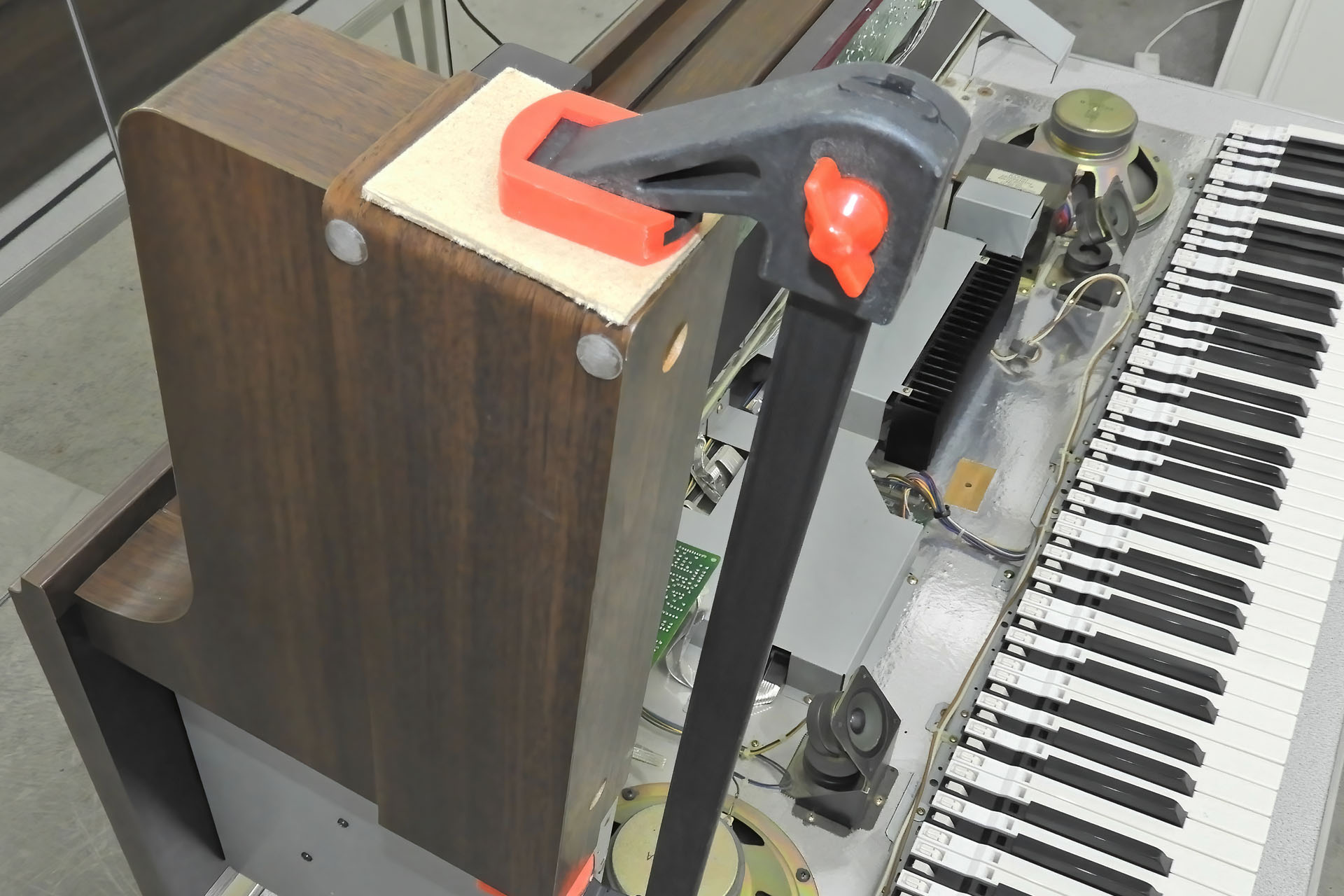
At 59kg, I needed some help to move this beast and take it apart. My helper elves were on the ready and between us, things were eventually good to begin.
My helper elves, daughters Katana (left) and Tsunami (right)... not misbehaving, for a change.
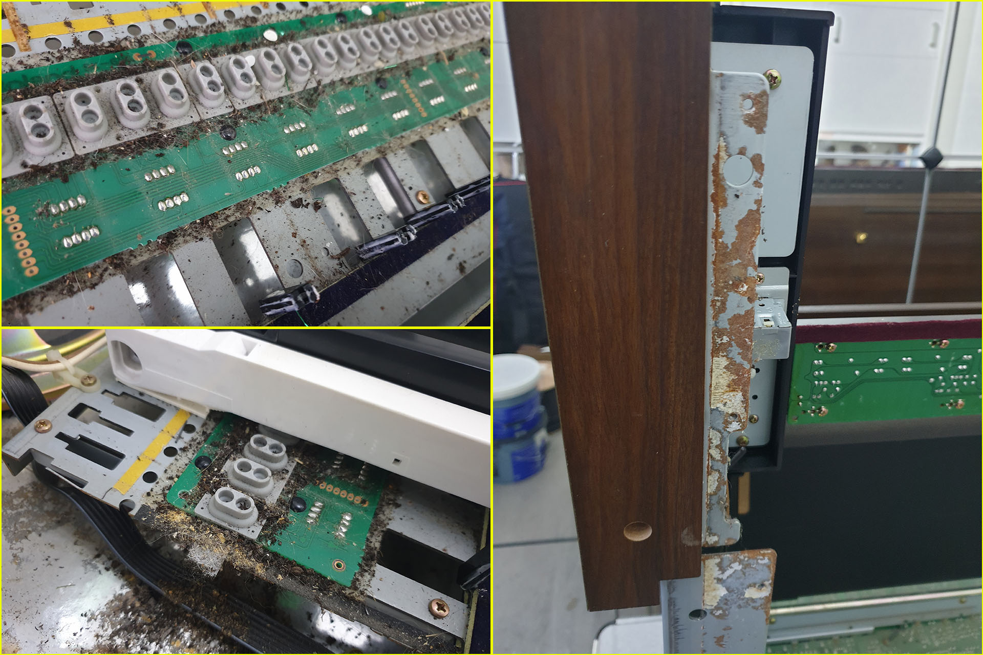
It took me a while to get this thing open but once I had, I realised why. At some point in its thirty-three-year life, a fluid spillage had occurred on the front left of the keyboard. Left unattended for years, this had the effect of ‘sticking’ the left-hand panel to the bottom-case. 🙁 The laminate (artificial wood-effect veneer) on the front of this panel had also come away slightly, presumably from the spillage. Fortunately, the laminate hadn't split so this could easily be reglued. At the moment however, this was the least of my worries. For now, I’ll just tape it up so that it doesn’t rip off when the piano is moved.
Extensive fluid damage on the left side of the keyboard in this poor ol' Roland HP-3700.
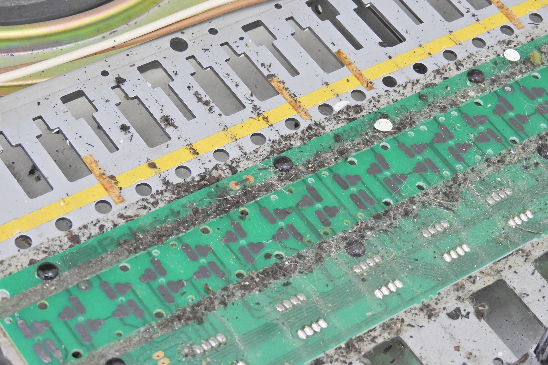
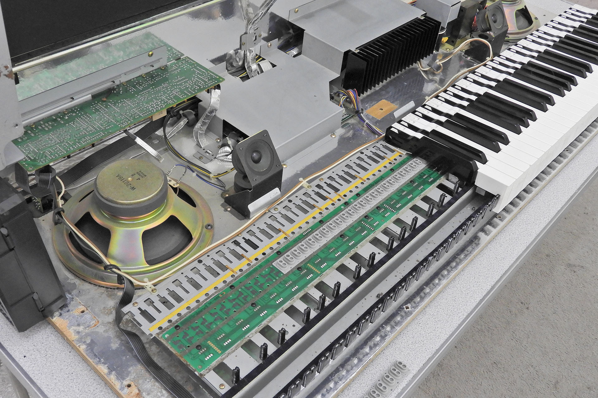
Performing a quick internal inspection and then switching on the piano to test all functions, I noticed that the bottom-A key was dead. Hmm… In fact, it was quite apparent that the left side of the key contact strip and the contact PCB weren’t in great condition at all.
Rubber key contacts off and check out over thirty years of dust, dirt and loads more interesting stuff.
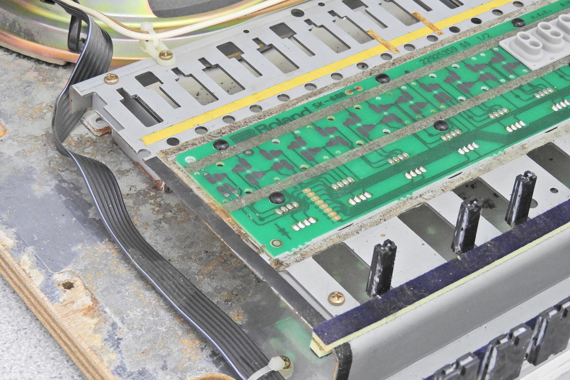
The keyboard construction on these pianos differs from that of Roland synthesisers from the same period. Being a piano (and not a synthesiser), the keys are obviously weighted and I have to say, are beautifully balanced. Unlike its synthesiser brothers and sisters, the HP-3700’s black keys can be removed without having to take out adjacent white keys. With a small flat-headed screwdriver, a gentle push in the right place and a nudge to the rear, the black keys pop out. With a similar action, the white keys slide out forwardly. An amazingly elegant design!
After removing a bunch of keys, cleaning the respective key contact strips and surrounding areas, I replaced the contact strips and keys and then tested. Everything played fine, except that bottom A key, of course.
Here's what the left side of the keyboard looked like after an initial clean. Not quite new but a lot better than it was.
I explained my findings to the customer and even sent some pictures. Well, he soon got back to me and we agreed a price for a full service. I explained that I probably wouldn’t be able to fix the bottom A key as the connection between the carbon pads on the contact PCB and the tracks, had been damaged. He accepted this and asked me to proceed anyway.
I’d already got wind of what was underneath the keys and indeed on stripping the entire keyboard, I found dust, dirt, round bits of paper from a paper punch, Christmas tinsel, cat hairs (a lot) and even a small stone. This was going to be quite involved, I thought.
TAKE HEED...Just like an acoustic piano, these instruments had beautiful keyboard covers which conveniently slide backwards and into the body of the piano to expose the keyboard when you want to play. If you have a Roland HP series piano or something similar, PLEASE use it!!! When not in use, the piano's keyboard cover (or lid) should be pulled forward to prevent contaminants falling in between the keys. Protecting the keyboard in this way also reduces the discolouring effect of ultraviolet light on the white keys so they’ll stay white for longer and won’t slowly fade to a beige yellow colour.
If your piano has a cover like this, USE IT! And please don't think that the cat can play an Elton John song. IT CAN'T!
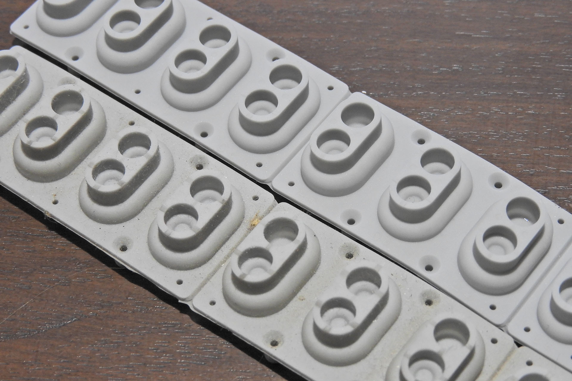
I did my usual hot soapy water bath thing for the rubber key contact strips and indeed removing them half-an-hour or so later, revealed their original grey colour and not the dusty light brown that they were before. They all needed a very light scrub after which I left them to thoroughly dry for a couple of hours.
Roland HP-3700 contacts before and after cleaning. No, please don't make me tell you which is which!!!! Of course the important parts (the carbon nipples) are on the underside of the bubbles.
While the rubber key contact strips were drying after their bath, I continued with phase 2 of cleaning the inside of the piano.
I continued with scraping off loads of crap, vacuum cleaning, dusting and then cleaning the area where the key contact strips will go. Yes, it took ages and while I was doing it, my mind drifted back to my days at Roland UK. Sometimes we’d be short of stock and would buy a load of big HP pianos from Roland Benelux. I’d come in with the service team on a Saturday and we’d convert them from 220V to 240V, also swapping out the 2-pin IEC C10 socket for a 3-pin C14 type. Three or four of us worked on one piano. Today I only have a couple of (small) elves!
Right, so the inside of the piano looks a lot better. The fluid spillage ensured that it’ll never be as good as new but pretty much all the crap that shouldn’t have been inside, is now gone.
After a second round of cleaning, I reinstalling some of the rubber key contacts and keys. Suddenly things started to look and sound a lot better.
Okay, so now that everything's starting to look good, I decided to have a closer look at that bottom A key again. Yeah, I know but this is exactly the kind of challenge that I was put on this earth for! 😊
There are three contact PCBs that are linked and that run the length of the keyboard, sitting underneath the keys. In between the bottom of the keys and the top of the contact PCBs are rubber contact strips. One strip will run under several keys. A pair of ‘bubbles’ in the contact strip will fall under each key and in each of those bubbles is a carbon nipple. In the rest position, there's a gap between the carbon nipples and four carbon pads on the contact PCB.
When a key is pressed, the rear two carbon pads on the contact PCB are shorted by one of the carbon nipples in the respective rubber bubble. The action is followed by the shorting of the front two pads via the second carbon nipple in the respective rubber bubble. The time between the first nipple shorting the rear contacts and the second nipple shorting the front contacts, is converted into velocity by the instrument's on-board computer. This is how the piano ‘knows’ how hard you’ve hit a key.
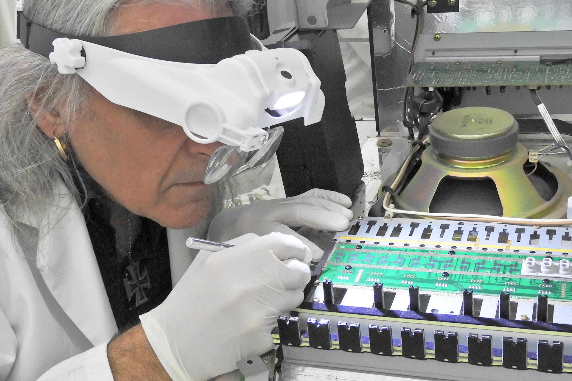
Measuring the continuity between the four carbon pads on the contact PCB under the non-functional bottom A key, revealed that the integrity of three of the four pad / track connections was good and that only one pad / track connection was broken. That wasn’t as not as bad as I thought it would be and so I figured on trying a little liquid carbon to fix this.
Repairing the broken carbon pad / track connection on the keyboard contact PCB requires a lot of patience.
Regular visitors to my site may recall my post of 19th November 2020 which featured an Alesis MMT-8 refurbishment. I used liquid carbon to repair the switches on that sequencer which three years later, are all still working. At between 35 - 40 GBP for a small kit, the good stuff is quite expensive but for this Roland HP-3700 keyboard service, I figured it was worth it.
Well, my first attempt with the liquid carbon wasn't successful. Remember; I didn't really want to touch the duff carbon pad itself but repair the connection between it and the copper track that it's connected to. Despite having cleaned the area thoroughly with IPA (avoiding the carbon pad, of course), the liquid carbon wasn't adhering too well to the copper track. I tried again but with a slightly different application technique and this time I got lucky. After fully reassembling the piano’s keyboard, the bottom A key sprang to life. Oh wow! RESULT!!! In fact, the whole piano now sounded and felt amazing.
I know what you're thinking and I didn't forget about the laminate that had come away from the left cheek. Being on the point of putting the piano back together that evening, I held back and decided to let the glue dry over night. Yes, it was really frustrating!
The fluid damage meant that this particular Roland HP-3700 keyboard service ended up taking three days to complete. I also needed help to move and even dismantle this thing. As I’ve already intermated however, there’s just no way I could charge for that amount of time and... don't forget the cost of the elves (yes, they're expensive). Fortunately, for my customers who I care about dearly, I love what I do and I want to do what I can to keep these beautiful instruments going for a little bit longer. Sometimes that means taking a bit of a hit but what the hell.
My only regret about this job, is that I didn't get to see this HP-3700 fully working piano back on its stand. 🙁 or did I...
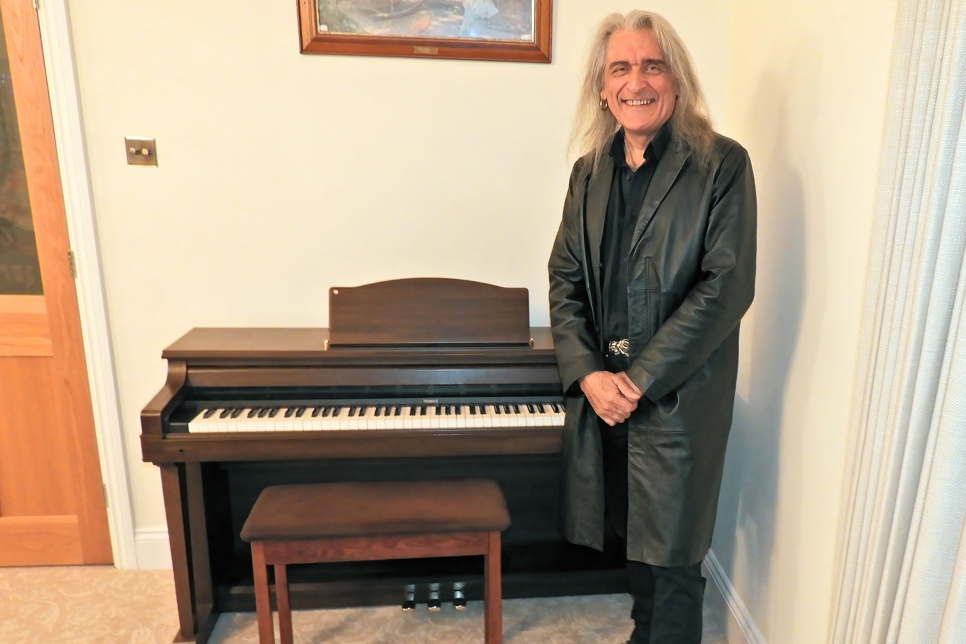
The day that Peter collected his beloved Roland HP-3700, he couldn't find the cable. I advised to get one off Amazon but he messaged soon after asking if I could order it and send it to him. That evening was quite nice particularly after all the rain we've recently had. It was also mild and warm so I decided to take my Jag out for run. Well what-the-hell, seeing as Peter only lived twenty miles away, I decided to run over an IEC C14 mains cable for him. While I was him, he offered to take a snap. 🙂
And I finally got to see the Roland HP-3700 complete on its stand.
At the beginning of this post, I sang the praises of the HP-3700 and other similar pianos of the same era but perhaps I should reiterate the point; these pianos are very underrated instruments. Unlike many synthesisers from that time, some of which are now established classics, these pianos haven’t been able to hold their prices but don’t let that fool you. These are beautiful instruments and lovely pieces of furniture which have lasted decades. If maintained, these pianos could keep on making music for decades to come. If you have one of these, please keep it! Oh and do think about getting it serviced.
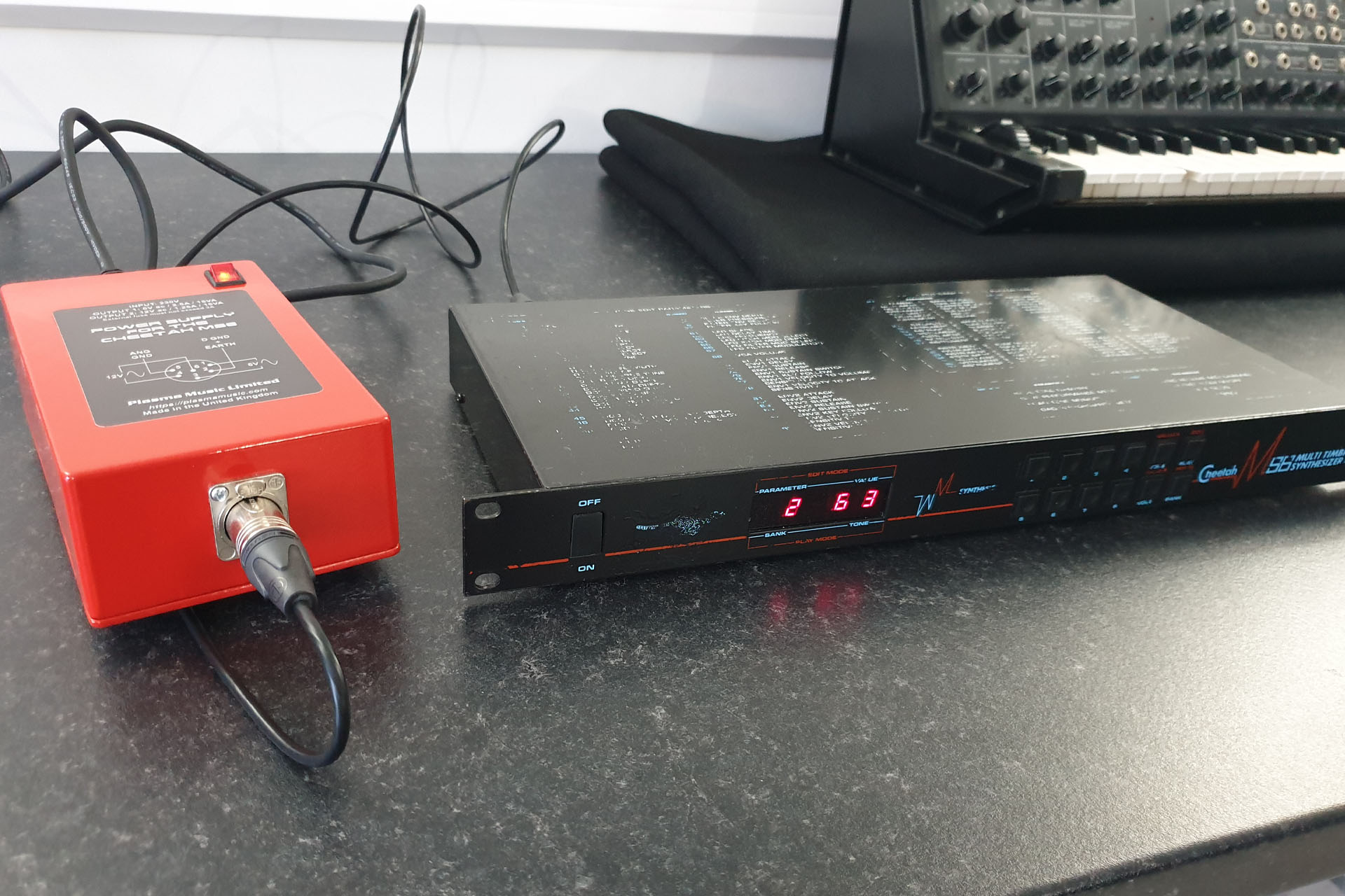
A few weeks before Christmas 2020, I was contacted by someone who’s Cheetah MS6 had not just blown up but had also tripped the electricity supply in his house! The upset MS6 owner sent me his unit and to cut a long story short, I ended up building an external power supply for the MS6, prior to repairing it.
The customer was then reluctant to pay for the repair and the power supply. Being quite amicable, we agreed that I could keep the MS6 to sell. To be honest, I just wanted to get my money back on the power supply and the repair.
While the Cheetah MS6 is a lovely little (British made) synth module, the power supply is well, crap and so I thought it a good idea to document the build of my external power supply in a post of 27th January 2021. I couldn’t believe how many enquiries I received and although frightfully expensive, I've lost count of how many of these things I’ve built now.
Anyway, after five minutes on ebay, that ol’ Cheetah MS6 got snapped up and indeed someone picked up a bargain. As I recall, it ended up travelling in the Manchester direction.
Well, last July, I was contacted by this dude who, it would seem, ended up with this particular MS6… but without the power supply!
The guy who bought the MS6 off me via ebay, must have eventually sold it and sadly, it would appear that the next owner passed away. The current owner (Charlie) then bought it at a house clearance auction.
I really couldn’t believe that this was the same MS6 but Charlie sent me pictures and indeed, it was the very same unit on which I prototyped my external power supply for the Cheetah MS6.
Charlie wanted his new MS6 up ‘n’ running and so he sent me the unit last August with a view to build another power supply.
It feels quite strange, virtually doing the same work twice on exactly the same piece of gear but like the post heading reads 'occasionally weird things happen'.
The Cheetah MS6 is an enigma. Launched in the late eighties by a small British computer manufacturer, this rather unassuming, multi-timbral, six-voice (twelve-oscillator), analogue synthesiser module is loaded with CEM 3396s and sounds amazing. It's such a shame that it doesn't have a couple of frills like chorus on stereo outputs, for example. On the other hand, the range of sounds is extensive and the quality of lush analogue sound is just so beautifully vintage. 🙂
UPDATE - 1st November 2023
This morning I received the most lovely telephone call from Charlie. He'd called to confirm receipt of his Cheetah MS6 including my external power supply and just wanted to express his gratitude and amazement at the build quality of the system. 🙂
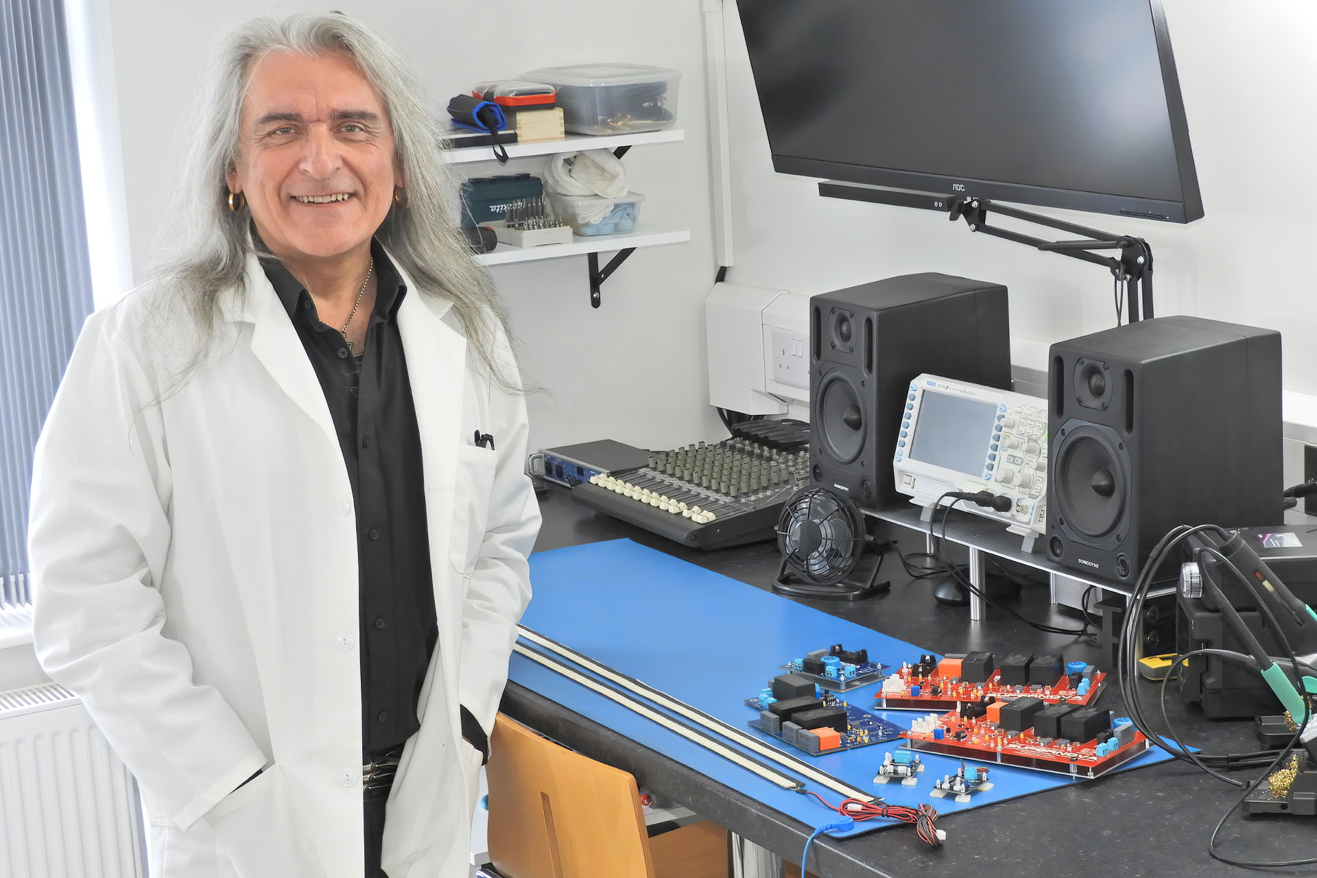
THANK YOU to all my customers for your support! I didn't have a 'holiday' as such but simply had to make time to finish off my new premises. Now I feel like a holiday!!! 😀 This week though, I'll be jumping repairs and order-builds that have come in recently so rest assured that things are back to normal.
As many will know, I hate DIY mainly because I don't think I'm very good at it. Having said that, this final phase of the project has taught me a lot of patience. Being fussy, I've learnt when to draw the line. The property is a self-build house from the seventies and no adjacent walls are quite perpendicular and no opposing walls are exactly parallel. Kind of good for a recording studio but a pain to paint, decorate and build stuff in. Of course I also learnt a lot about paint, LOL.
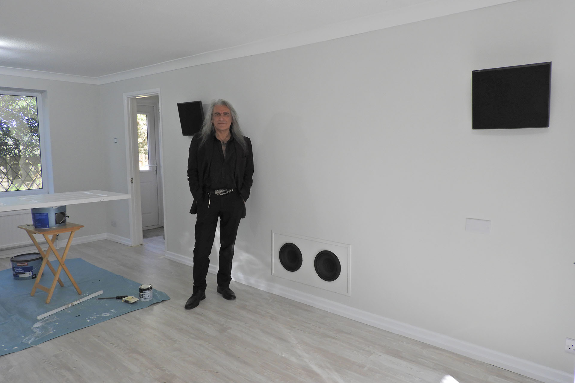
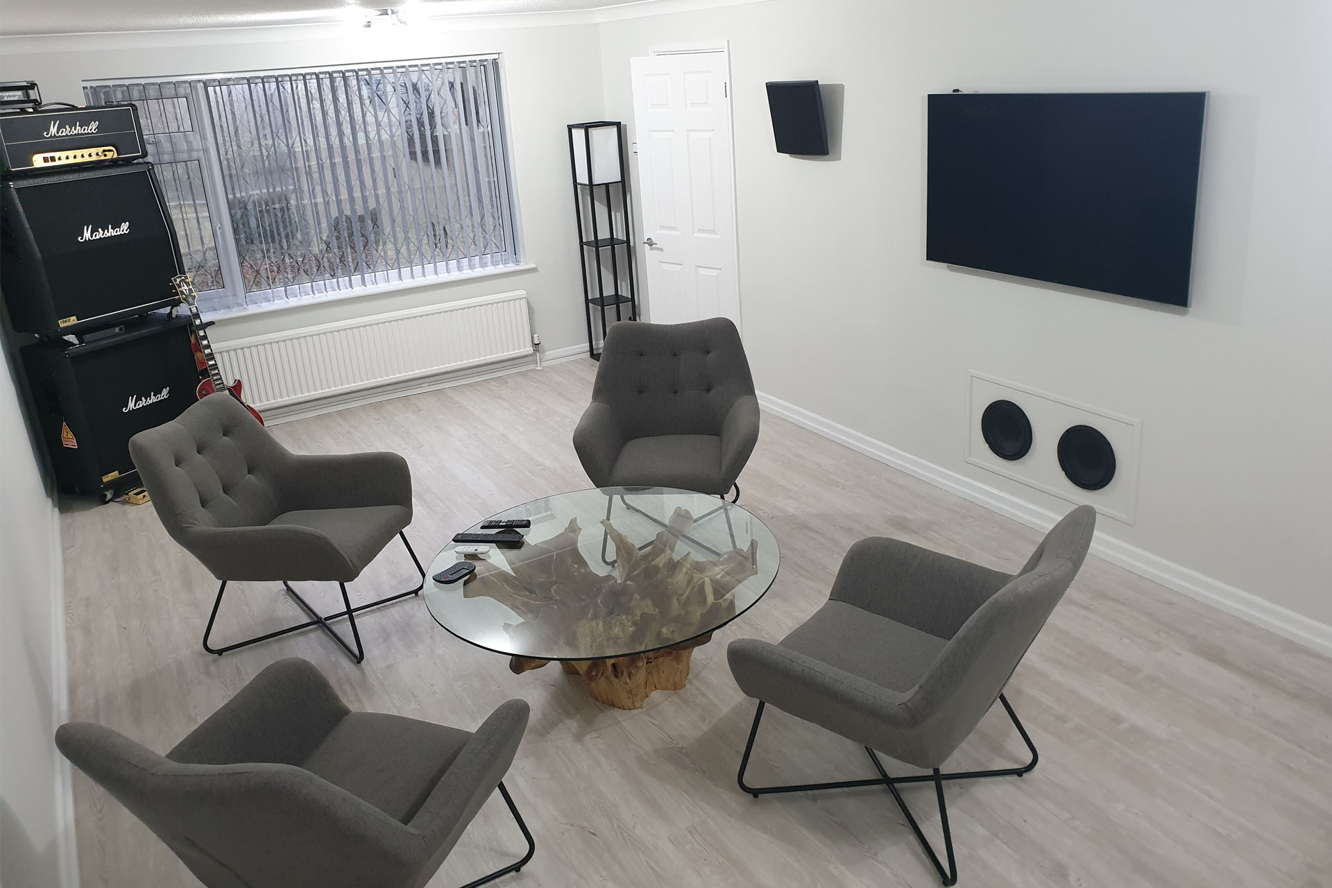
as you can see in the picture above, I still have a couple of things to finish off like the recoat of the other side of the door that's behind me and most obviously, I need to mount a TV screen.
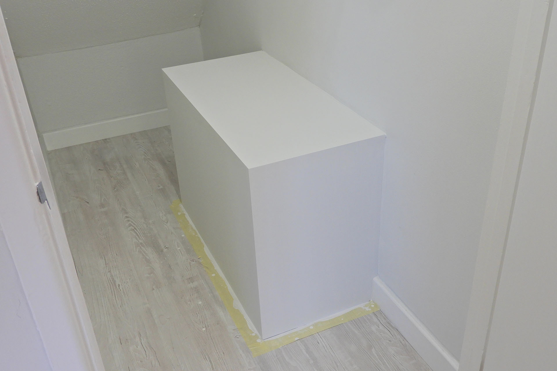
I'm delighted that my sub-bass enclosure is almost finished. A couple more coats of paint and I can think about putting in the hi-fi. I'll be doing a feature on the build of this soon. Of course it's the front that most people will be interested in.
Furniture has been ordered and while the seating will be here in a few days, I'm not expecting the bespoke coffee table before the end of the year! 🙁
UPDATE - 23rd October 2023
Last week I received an e-mail informing me that my teak root coffee table was ready to be delivered. WOW!!! That's like several weeks before I expected. On the day of delivery, I received another message saying that the delivery van had broken down. 🙁 Oh boy... Anyway, to cut a long story short, it got delivered today and I'm delighted to announce that my lounge is now F I N I S H E D which means that the whole place is now presentable and just the best place for me to work.
Apart from being a place to receive guests, I'm look to resume my video exploits very soon. Of course the area just isn't big enough to host bands, not even solo artists, really. I am however, looking to do kinda podcast things, chat shows and stuff like that. Let's see how it goes...
JUST A QUICK REMINDER...
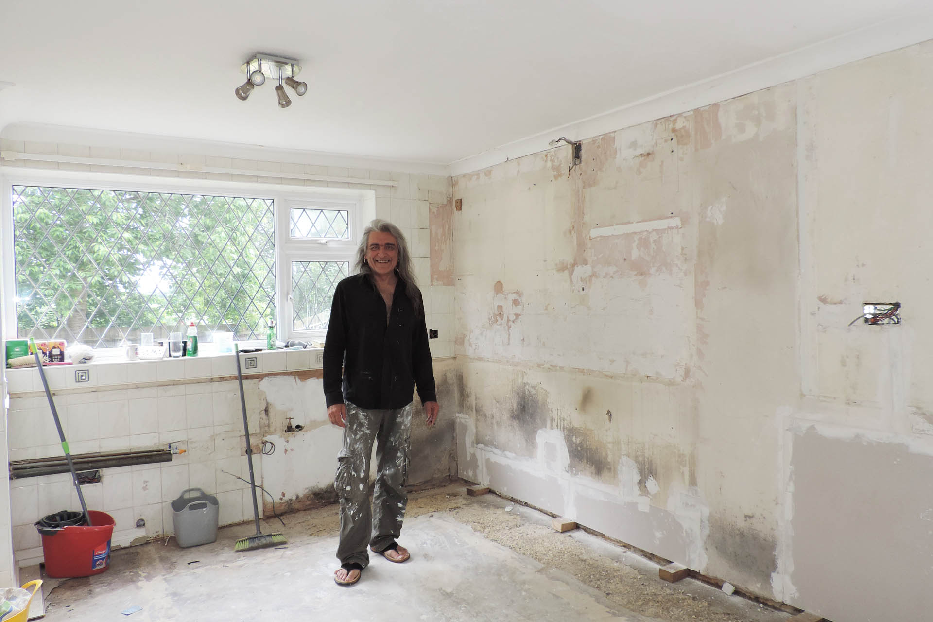
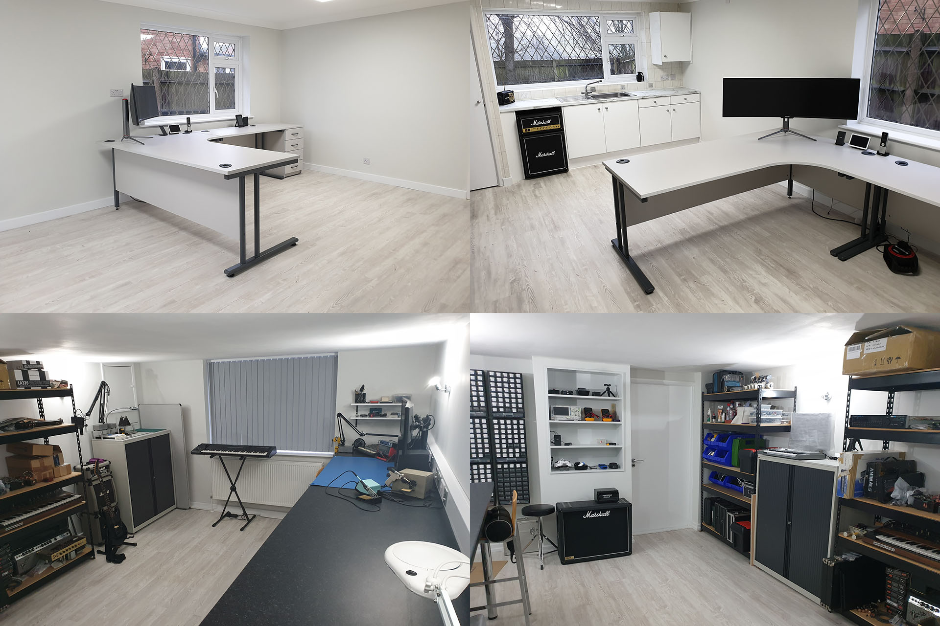
So back in 2021, I had just moved in and the task of getting this space together seemed really quite daunting. Anyone who loathes DIY as much as I do, will understand. It wasn't just a case of a few licks of paint. There was repair work to do, I had to fix things to keep out the rain, doors needed to be recut, repaired and in one case, a new door had to be fitted. I built a shelf unit in the lab. That was after I installed an 800mm worktop. There were rack enclosures that I had to build for the studio. Oh boy. And of course I was rebuilding my business and was determined not to let down my customers.
I ripped out the old kitchen with a view to make the kitchen / diner into a kitchenette / office.Of course, my Marshall fridge / freezer got installed ahead of any office equipment! Well, you have to, right?!?!?
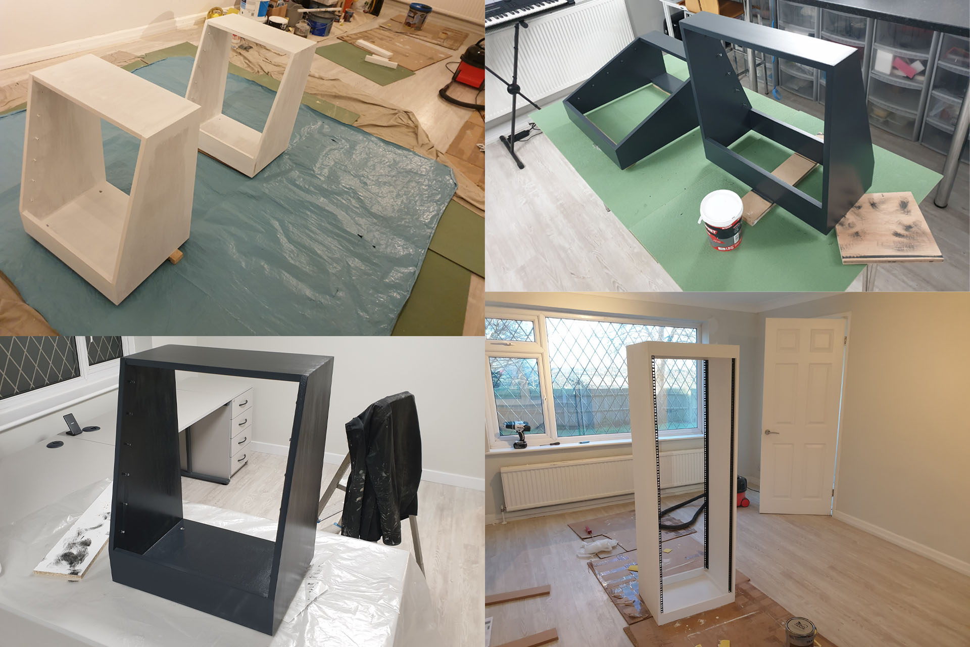
I had a lot of EMS rack cases but they were meant for the road. In the studio, I wanted something a bit classier and decided to build my own 19-inch rack enclosures. 'Glutton for punishment' comes to mind.
It took a long, long time to build the 19-inch rack enclosures I needed. Waiting for paint to dry, oh boy!
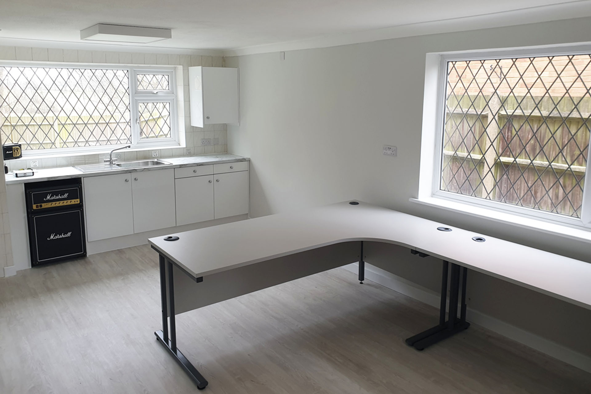
I was so busy with repairs and designing stuff so getting the lab up 'n' running was an obvious priority. Working in the lab was such a relief and fixing gear and designing peripherals for vintage synthesisers in my kitchen at home, soon seemed like a distant memory. The only problem was that I still had all of my IT at home so I was dashing between the new place and my home, fixing stuff and then doing admin. A no-brainer, the office was the next area to be completed after the lab.
After the lab was done, I had to get the office operational.
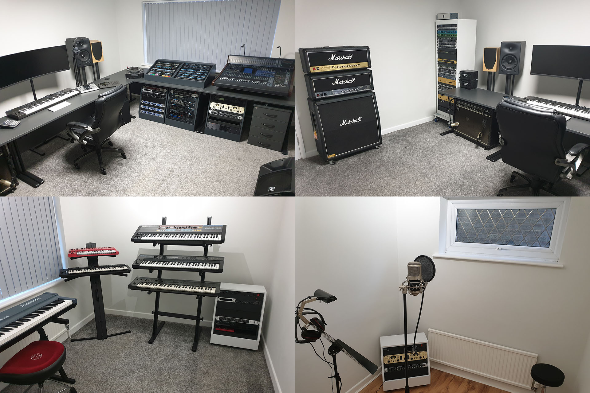
One thing visitors don't see are cables. I H A T E C A B L E S and planning just how everything was going to talk to everything else without cables hanging all over the place, was a challenge I took on while I was, well... waiting for paint to dry, LOL.
With equipment roughly where I wanted it to be, the next task was to connect it all up... discreetly. I also had to consider sound treatment and ended up making my own acoustic panels (not shown).
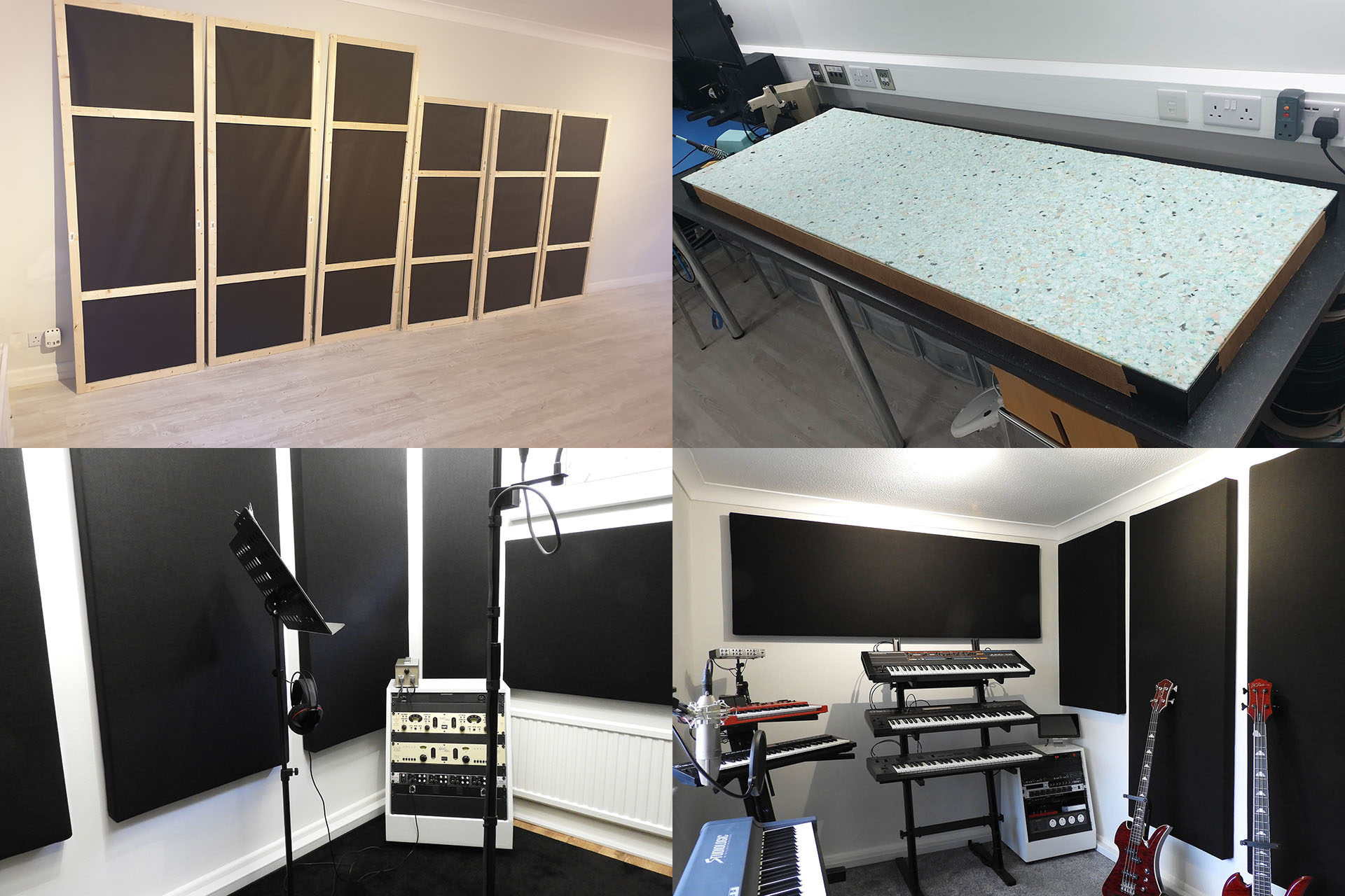
Planning and then implementing all the cabling in such a way as to keep it discrete, was a big deal but my work wasn't over by a long shot. I was well aware of the 'sound' of the studio. Hard, plastered walls gave all the important rooms a lot of reverb and that had to be addressed.
The walls of my previous studio were covered with foam acoustic tiles. While perfectly adequate, I wanted something a little more cosmetically pleasing and embarked on making my own acoustic panels. Like I said; glutton for punishment!
A long job making these but well worth it. Not only did the panels address the reflections but they also had the effect of dimming down the brightness and making things feel a little more cosy.
I started off this post by thanking my customers for their patience and understanding but I must also acknowledge friends and family, for their unwavering support. The new place is just an awesome work environment and my daughters both commented that the studio actually sounds better than what I had at Area 51, my previous studio on the local industrial estate. 🙂
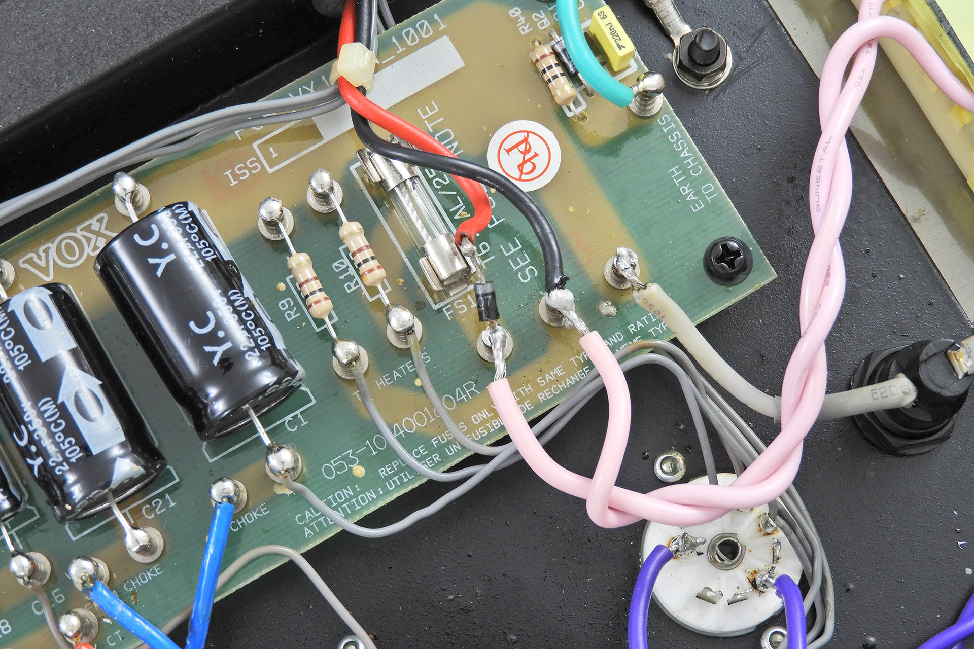
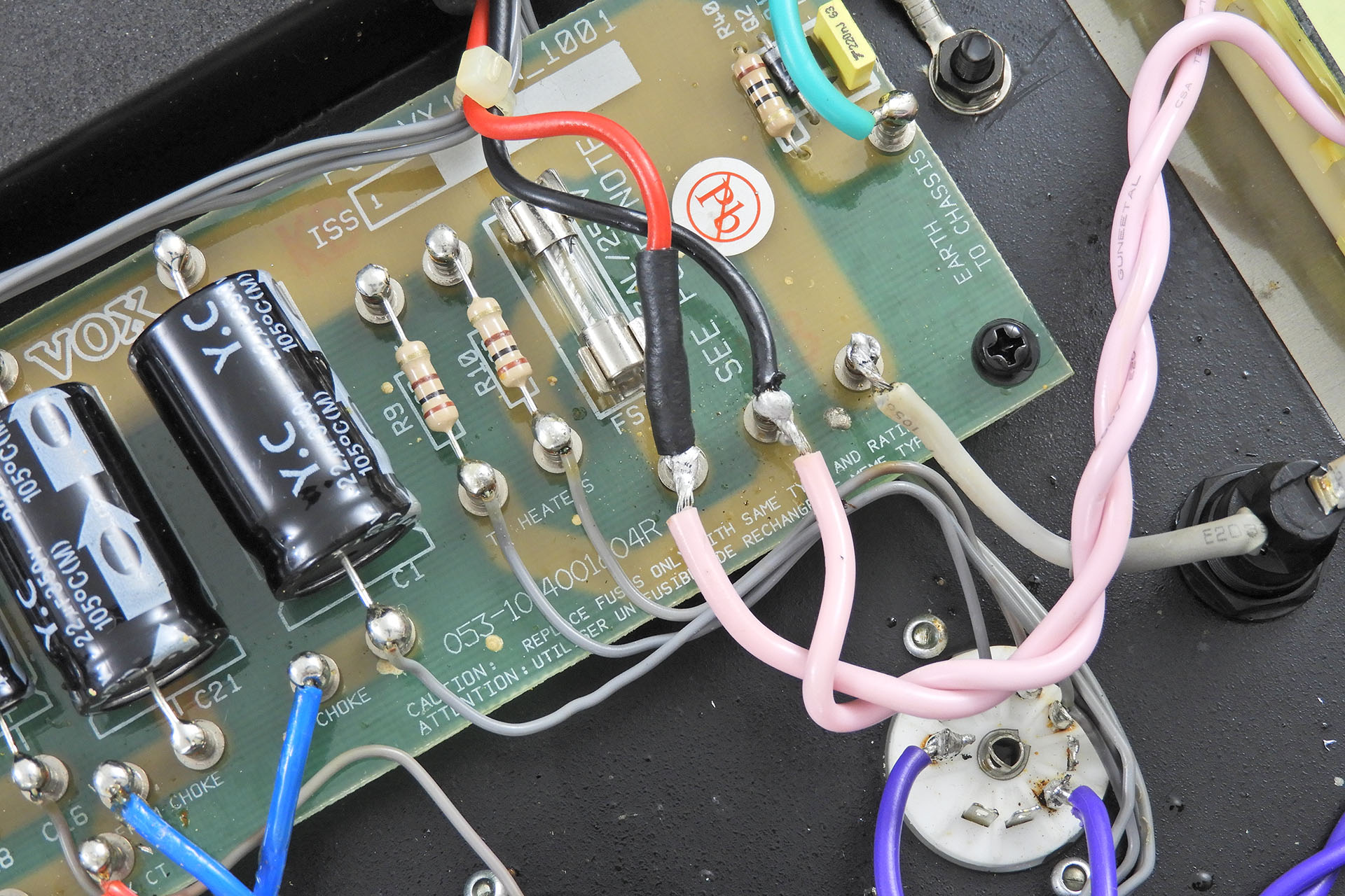
I'm taking a few weeks off next month so that I can complete my new premises (yes, it's more than two years) and I'd like to get as many units back to customers as I can before 1st September. Things like this dodgy amp wiring seriously don't help.
This Vox AC15HW came in smelling bad and the customer saying that it had started smoking. It was evident that the power transformer had fried. While doing the swap-out, I noticed the little fella (diode) pictured below, sitting uncomfortably close to a fuse. This just looked really bad so I decided to put a jacket on it (bottom picture). Better safe than sorry, eh?
I have a feeling that this amp had been repaired before so I'm reluctant to point the finger at Mr. Vox, on this occasion. 🙂
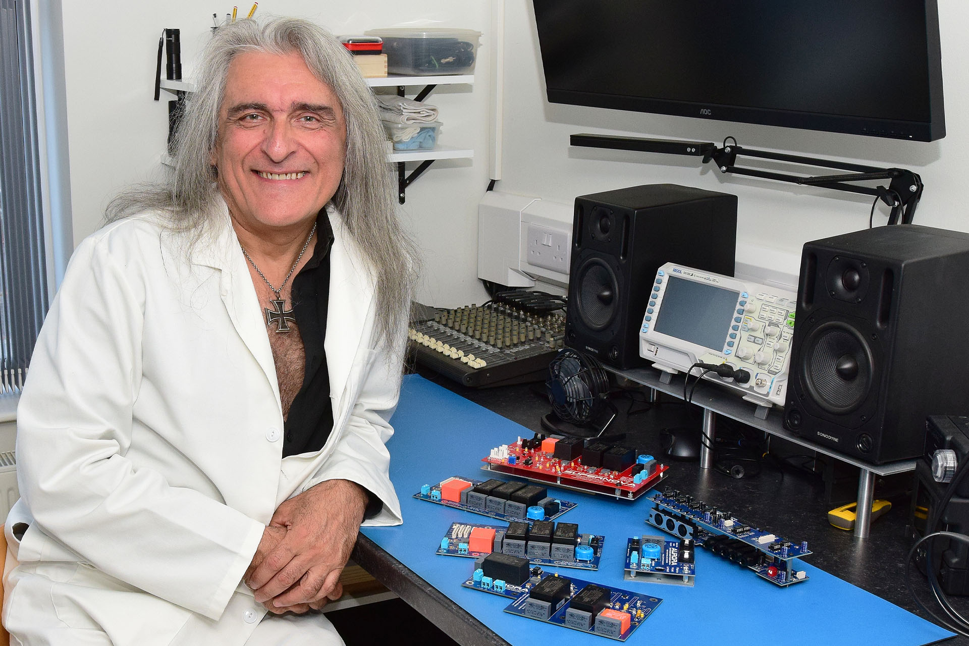
So far August has been well, a bit crazy. On top of an insane amount of repairs poring in, I've been busy building stuff and next week I have a meeting about a complete studio revamp. What the hell has happened?
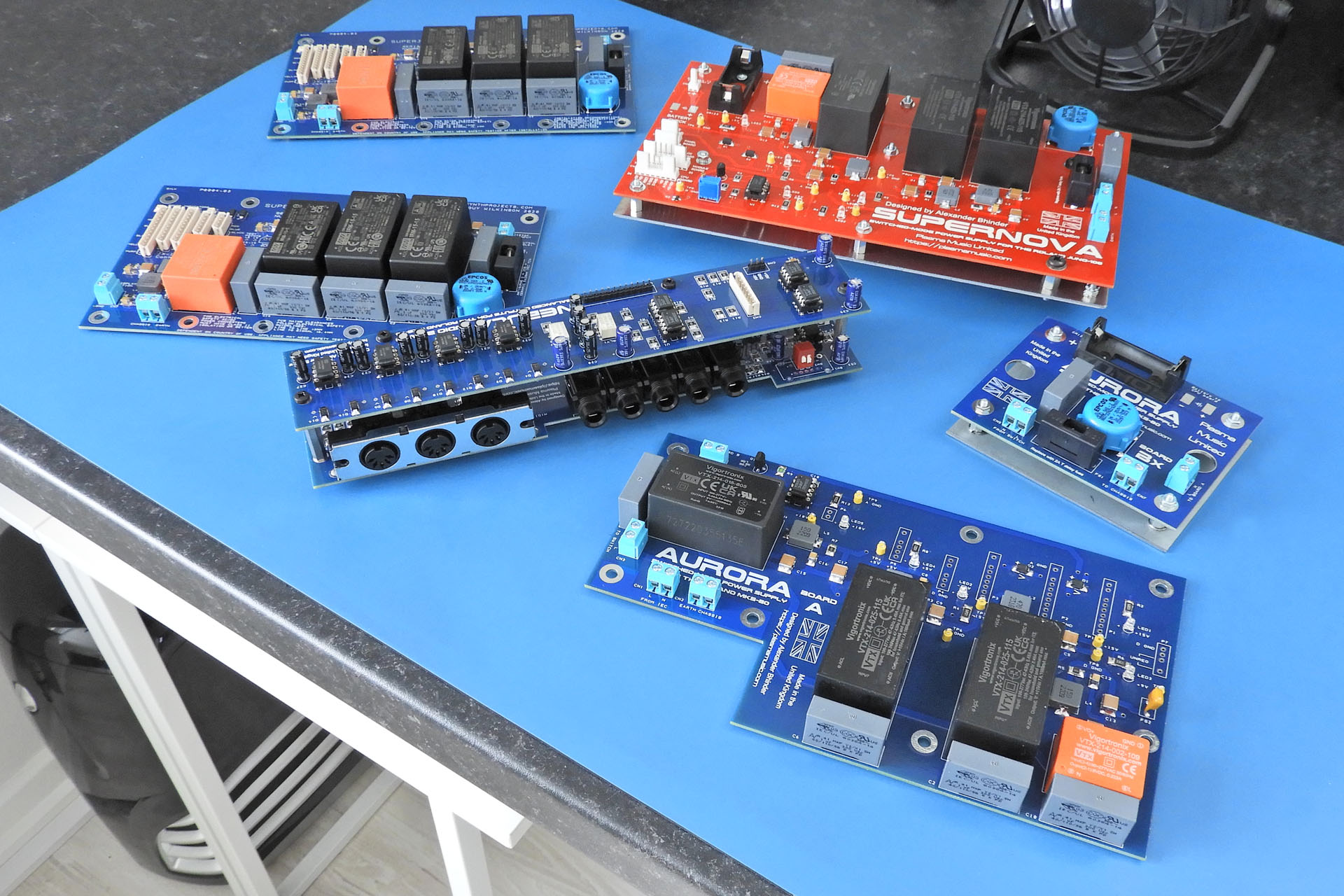
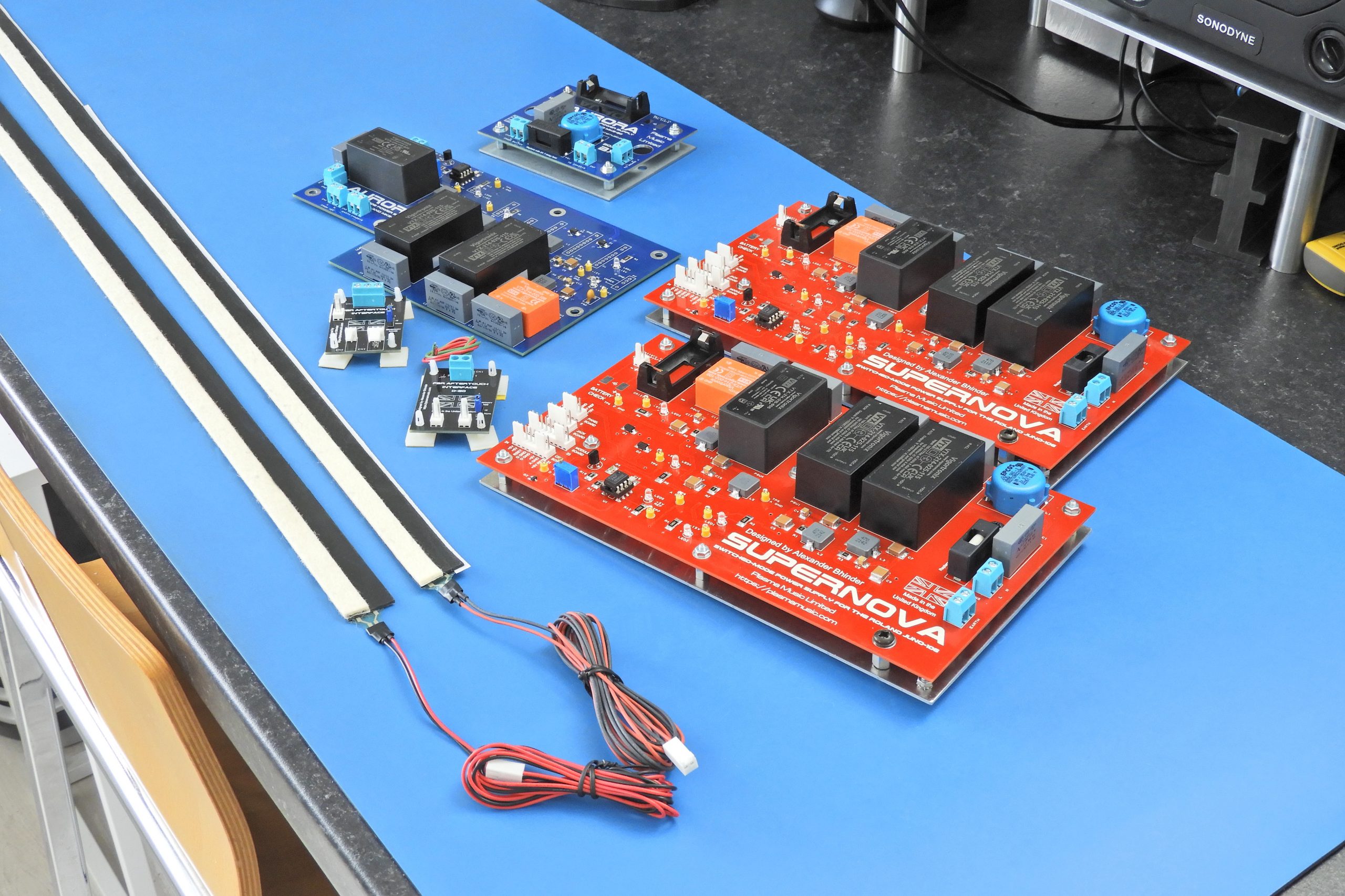
Pictured below are 'some' of this week's builds which will all be fully tested over the weekend ready to go out on Monday.
At the back in red is a Supernova modular switched-mode power supply for the Juno-106.
In front of that and also to the left are two of Guy Wilkinson's P0004 modular switched-mode power supplies for the Roland MKS-70.
In front of those is the dual-stacked Nebula balanced outputs jack-board for the Roland MKS-70.
And In front of the Nebula and also the small PCB to the right, is an Aurora modular switched-mode power supply for the Roland MKS-80.
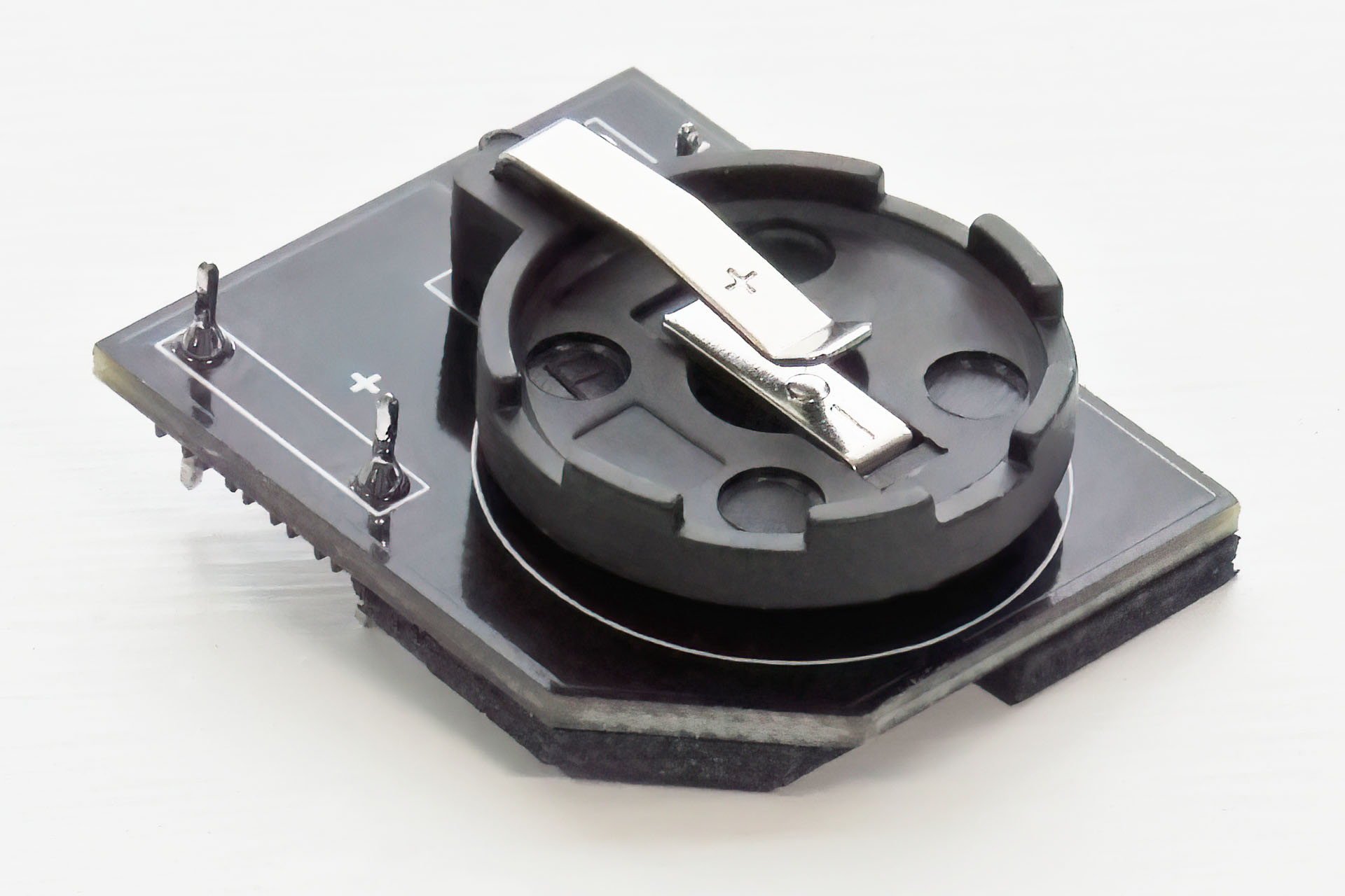
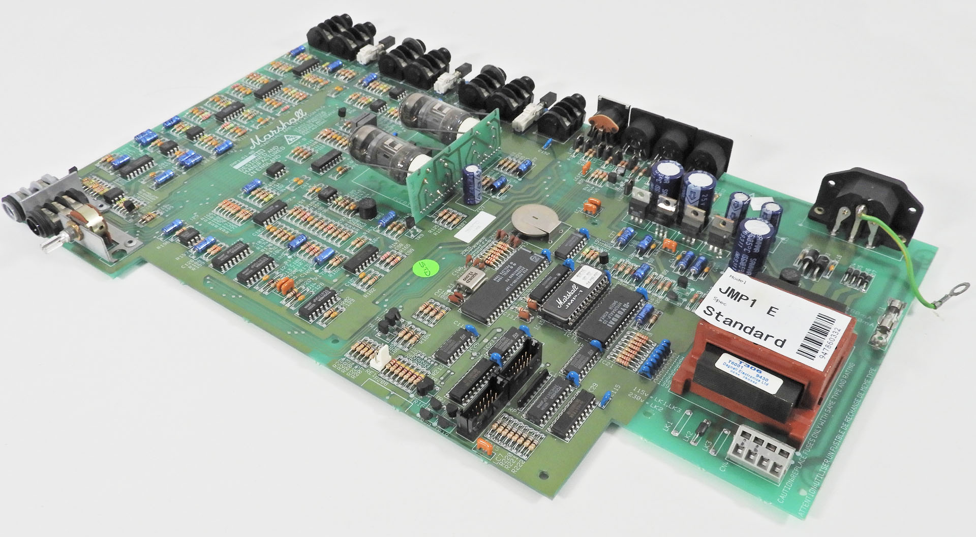
Not pictured because they're already boxed up, is an Eclipse bounce eliminator, a couple of my new CR2032 battery adapters and a PML-TX01 redesigned power transformer, all for the Marshall JMP-1.
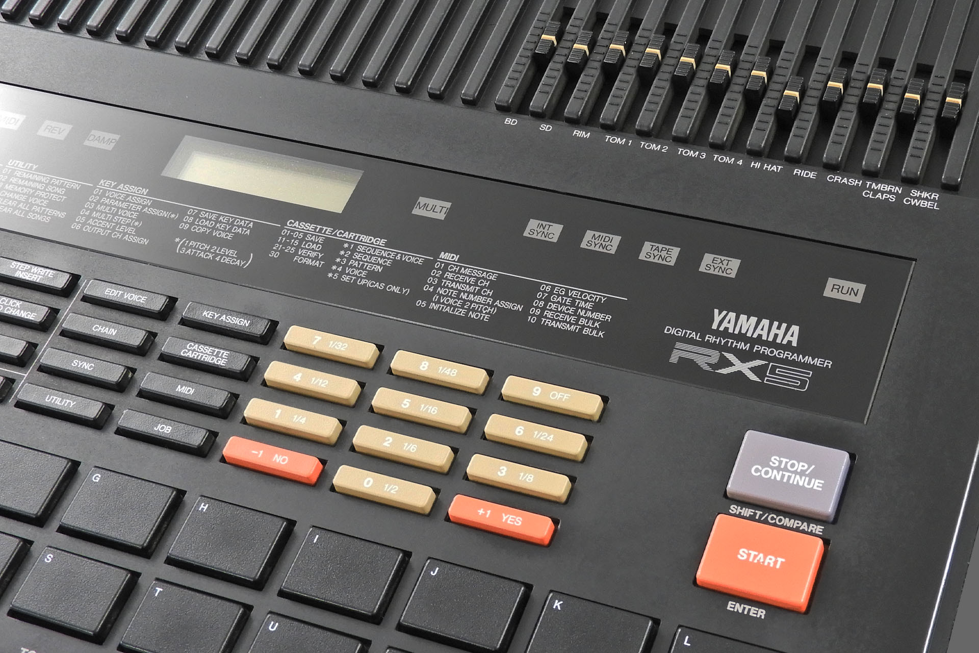
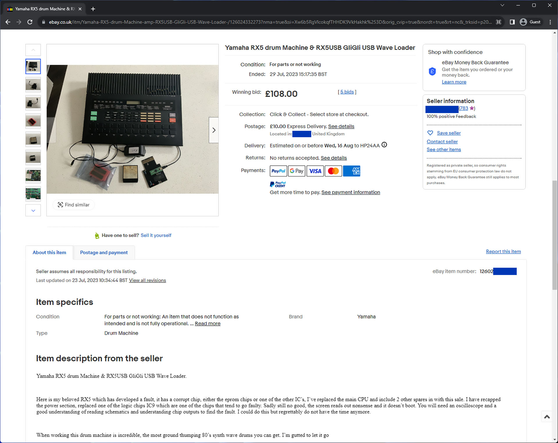
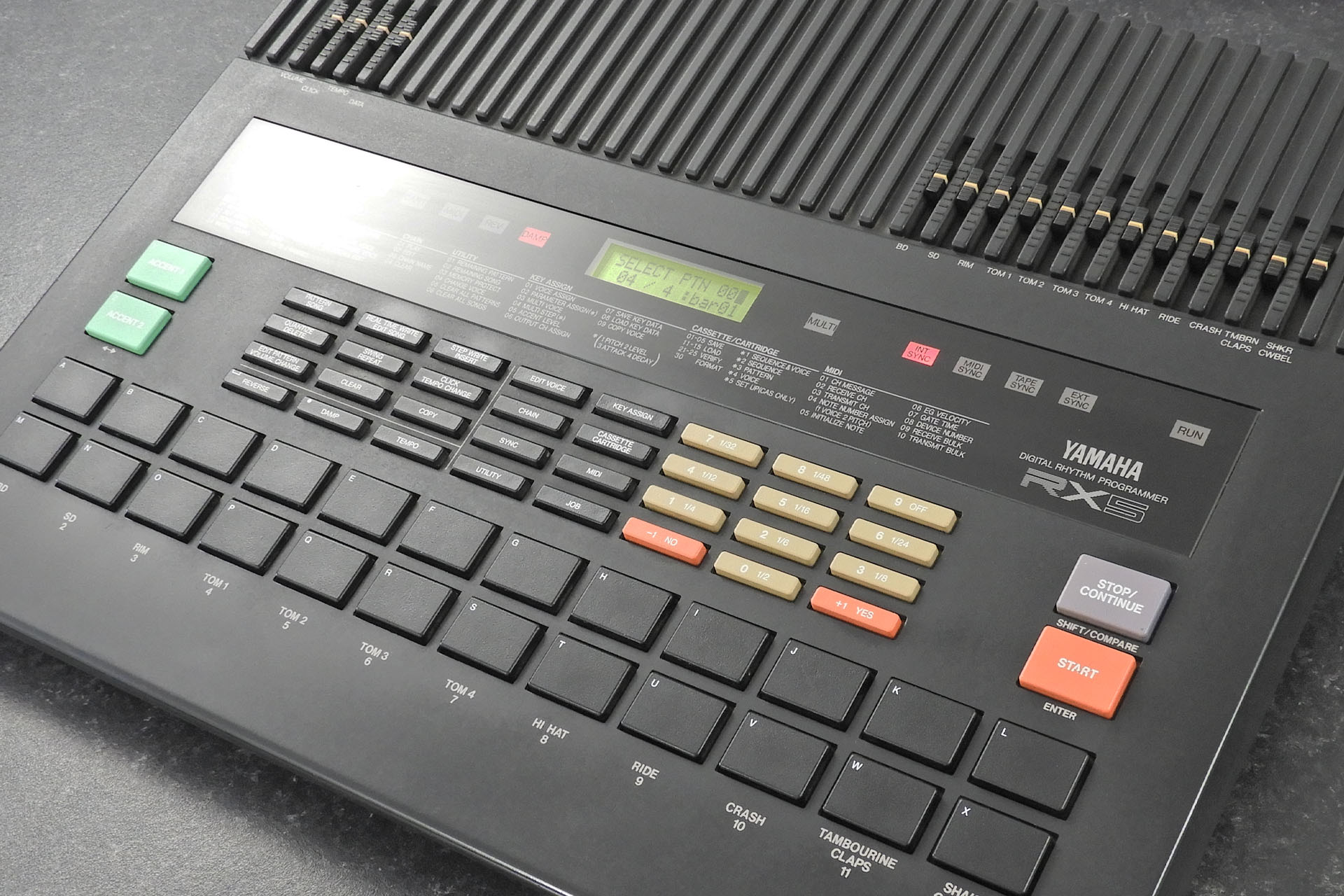
The Yamaha RX5 is one of my favourite drum machines and when I acquired an example that wasn't 100% working, it seemed like my next rainy Sunday afternoon would be occupied with a Yamaha RX5 repair (or two).
Every once in a while, I receive a mysterious parcel, sometimes from as far away as Japan. It took me a while but I eventually sussed out that my ex-frontman / singer, Rob would occasionally get the urge to buy me something. Anyway, a couple of years ago, one of those parcels contained a Yamaha RX5 drum machine (yes, you read correctly) that indeed had come all the way from Japan.
Being a die-hard Sisters of Mercy fan and like many, wanting to get those big Doctor Avalanche drum sounds, it was quite obvious where Rob was coming from. He'd given the game away, LOL! 😀
While much appreciated, the RX5 wasn’t in great cosmetic condition and outputs 10, 11 and 12 were dead. This wasn't a pad problem as I was getting MIDI. It was defiantly an analogue signal path problem. The machine had been opened before and on close inspection, the membrane cable that connects the main-board to the output board for example, didn't look in great shape.
Despite the issues however, this RX5 came in really useful for testing my Nebula balanced outputs jack-board for the Roland MKS-70. I made a special lead that connected four outputs from the RX5 to the audio inputs on Nebula, where the outputs from the MKS-70’s voice-boards would go. It worked like a charm but to be honest, I would have preferred to have a Yamaha RX5 in my keyboard room.
So, as you do, every once in a while, I’d check out the Yamaha RX5 action at the usual on-line places. Well, a few weeks ago, a RX5 popped up. Cosmetically in great condition it did have a fault and so the auction started at 50 GBP. To cut a long story short, I ended snapping it up for 108 GBP. On top of that, collection was only twenty-five minutes away from where I live. GEEEERATE!!!!!!
My patience paid off and I finally found a nice condition Yamaha RX5 for a very reasonable price.
When I went to pick up the unit, the seller showed me the fault and indeed as described, it simply wouldn’t boot properly, with garbled characters cycling randomly on the display and LEDs also randomly coming on and going off. It wasn't even possible to reinitialise the machine so something was clearly very wrong.
Having sussed out that the fault on the RX5 that Rob bought me, was down to a couple of faulty op-amps on the jack-board and that the fault on the unit I’d just bought was on the main CPU-board, I did the obvious thing and just swapped out the main-board in my machine with the one I’d just bought. Okay, so now I have one pretty good condition, working Yamaha RX5. That can now go upstairs into the studio. Yippee!
I put the main-board from the unit I’d just bought into the case of my old unit. Of course, it still didn’t boot properly.
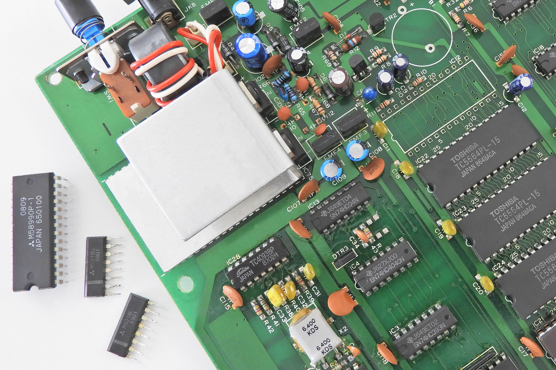
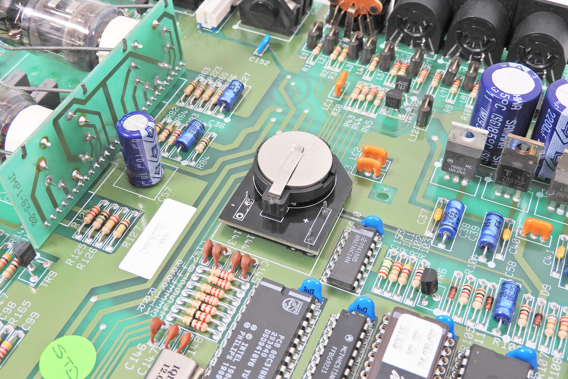
Before switching on loads of test gear, I always do a quick visual inspection. If the item in question will switch on, then I switch it on. On this occasion something was definitely not right as I noticed that an analogue-to-digital converter was getting rather warm. In fact, after half-an-hour or so, it was about 50°C while adjacent devices were only a little over ambient temperature.
A quick check of the power supply revealed that everything was good.
On a side-note, the RX5 power supply puts out +5V derived from a 7809 positive voltage regulator and -4V via a 7905 negative voltage regulator. The configuration is rather clever and unusually allows the heatsink on the 7905 to be connected to 0V.
So, normally associated with the DX range, the Mitsubishi M58990P 28-pin ADC can be found in many early Yamaha digital instruments from that period. Now-a-days it’s not too easy to source but I managed to find one that was unused and for a decent price.
The Yamaha RX5 main-board. To the right are the components that I removed; a M58990P and two M5218L dual op-amps.
Unfortunately, IC 12 (the M58990P) wasn't what was causing the malfunction. This ADC is simply for the data and tempo sliders. While it had to be replaced anyway (because it was cooking), I knew it wouldn't fix the problem as it doesn't have anything to do with the computer side of things. This RX5 still wasn't booting. Damn!
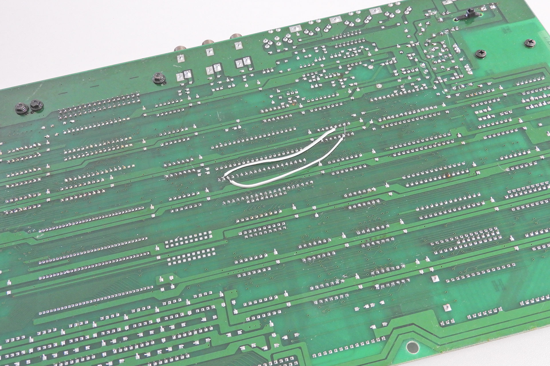
I had to dig a little deeper. Code just wasn't running on the processor and data line D3 was definitely duff. Checking connections and realising that the seller I bought this from had swapped out the 63XX series processor, I then discovered two broken tracks. Technically, there were actually three as there was also a break under two linked pins on one of the ICs. After fixing them, I still had a non booting RX5. 🙁
The guy I bought this off, tried to fix it by changing the HD63B09EP processor. While doing so, he managed to break a couple of tracks.
The signal of the FIRQ into the processor seemed to be playing up, looking like it was only running at about half the speed of what it should be and it kind of looked modulated. A lot of back-tracking and things were becoming quite challenging. I thought that the counter clue in conjunction with the symptoms, would point me in the right direction but intermittently, things like not all 'Chip Enable' lines for the three SRAM devices would come up. In fact, things reached a point which made me concerned that perhaps the firmware had become corrupted or perhaps the voice ROMs had been damaged. Even the SRAM wouldn't be straight-forward to change as there are three TC5564PL-20 devices.
Indeed I ended up changing a lot of logic and even burned a pair of new firmware ROMs.
Interestingly, this RX5, actually had three seemingly unrelated problems; the ADC, two (or three) broken tracks and some duff logic. Hmm... The guy I bought it off, threw in a GliGli RX5 USB card and I'm wondering if that screwed things up somehow. In his attempts to repair it, I'm sorry to say but it looked like he made the situation worse. Those tracks for example, didn't break by themselves.
All in all, my Yamaha RX5 repair took me several days and I hope I'm humble to admit that it wasn't easy. With a lot of digital interdependencies, tracking down the cause of bad data and address busses was painful and very time consuming.
While I was at it, I also changed the battery and replaced the cheep processor socket with a proper turned pin type. After putting everything back together, reinitialising the unit and restoring factory data, I switched it on and YES, life and.... SOUND!
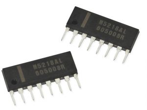
Yes, of course ICs fail. That's a big reason why I do what I do! While accepting the ADC going down and even a couple of logic gates, I have to admit to being quite surprised at the failure of the two M5218Ls. Remember that these were technically out of my first RX5. These humble single-in-line dual op-amps are used extensively in equipment manufactured during this period and are amazingly reliable, with a pretty good specification for the time. In fact, I can't remember the last time I had to change one of these, let alone two in the same machine.
Being ex-Roland, you wouldn't be blamed for thinking that I should almost have a natural affinity towards machines like the TR range and even the R-8 but I have to confess that the solid, punchy feel of the Yamaha RX5, was more my cup of tea than the rather traditional, rounded, perhaps even 'jazzy' sounds associated with Roland, at the time.
Yes, I know the RX5 is only 12-bit at 25kHz but just put the specs away for a moment and LISTEN! 😀
Had a busy weekend just gone building a load of stuff:
1 x Aurora replacement power supply for the Roland MKS-80
2 x Supernova replacement power supplies for the Roland Juno-106
1 x AT-JX-10 FSR- based replacement aftertouch sensor for the Roland JX-10
1 x AT-D-50 FSR-based replacement aftertouch sensor for the Roland D-50
Hmm... I guess I do look a little tired!
Despite a busy weekend building stuff for customers, I managed to find time to renovate this now gorgeous Yamaha RX5 drum machine.
Yeah, I know what you're thinking... being ex-Roland I should instinctively favour classics like the TR-808, TR-909 and TR-707. To be honest though, I've never been a big fan of Roland drum sounds. The Yamaha RX5 on the other hand, well... I just love it.
I often receive e-mails requesting I look into various aspects of this legendary MIDI valve pre-amp. One request I receive a lot, has led me to develop a CR2032 adapter for the Marshall JMP-1. This replaces the factory soldered battery, with a clip CR2032 holder allowing for the battery to easily be replaced.
Something to make our lives a little easier; my CR2032 adapter for the Marshall JMP-1.
While readily available several decades ago, CR2032 batteries with solder tags have dropped out of fashion and even if you can find one, there's a good chance that it won't be exactly the same as the one that fits in your gear. As I often say "the nice thing about standards is that there are so many to chose from".
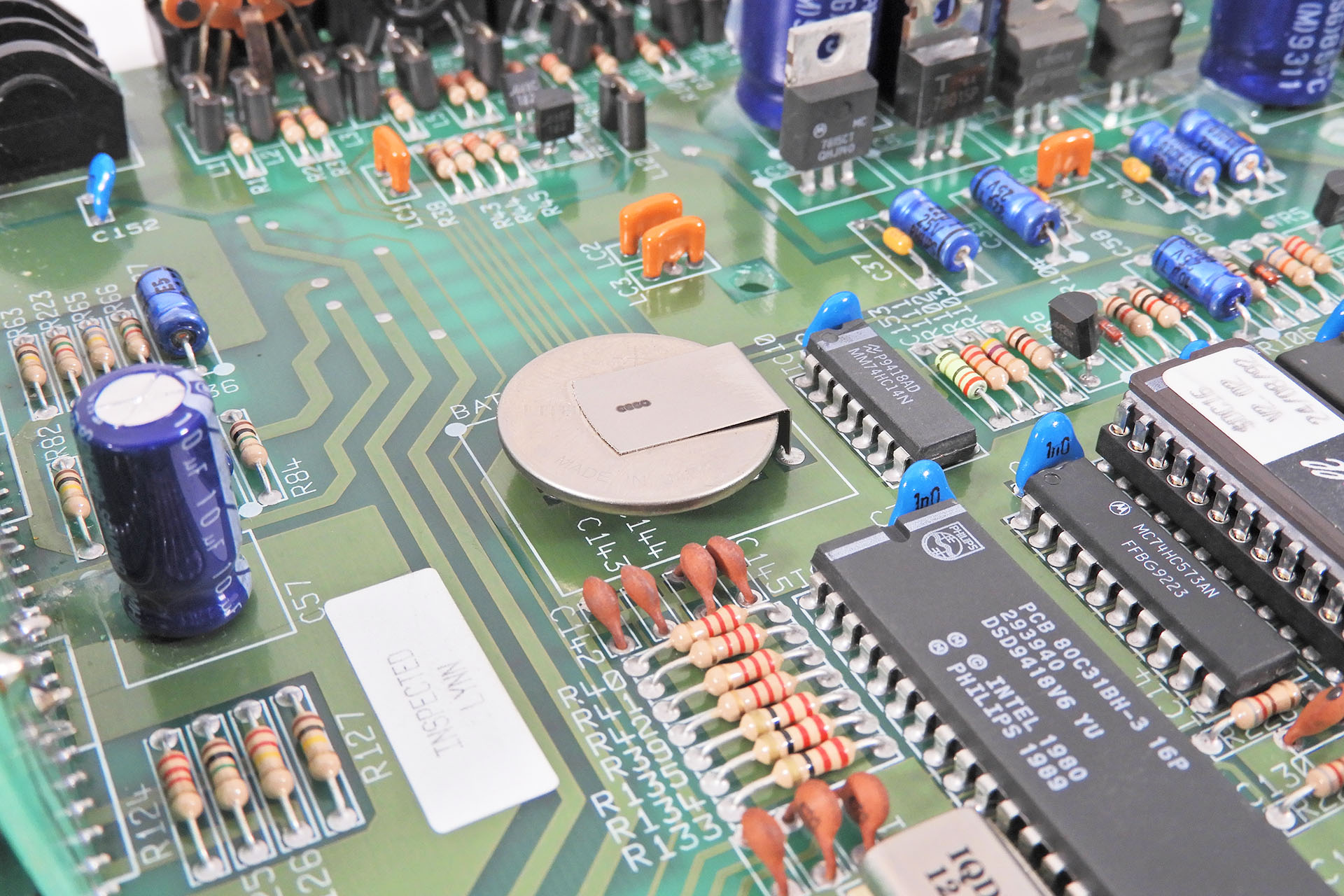
Here's the original battery in Marshall JMP-1. As you can see, it's soldered to the PCB.
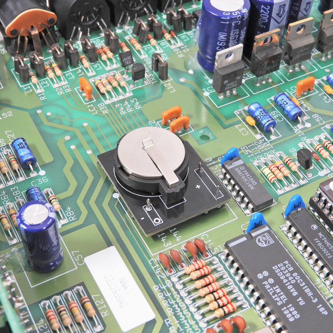
My little CR2032 adapter for the Marshall JMP-1 takes care of that, well at least in the JMP-1. 🙂 It's not rocket science but can make life a little easier.
Unfortunately the main PCB has to be removed to fit this adapter and that's not an easy job. It's a process which requires time, patience and of course, the right tools but which is detailed in the installation manual, available after purchase. In fact, the installation manual goes into so much detail, it's ended up being the most comprehensive manual I've written for something so incredibly small!
This bad boy takes a lot of work to get to and doesn't come out easily but don't worry, my detailed and fully illustrated installation manual will help you all the way.
To prevent tilting during battery swap-out, the underneath of the adapter has a 2mm rubber pad which keeps it very flat and secure.
Fits like a glove and perfectly secure thanks substantial support underneath the adapter PCB.
UPDATE - 9th February 2024
With so many bits 'n' pieces available for the JMP-1 and always thinking of new stuff to make for our favourite MIDI valve pre-map, I decided to make a category just for the Marshall JMP-1 in my on-line store. You can check it out here.
IF YOUR JMP-1'S BATTERY ISN'T DEAD BUT YOU STILL WANT TO SWAP IT OUT, THEN PLEASE DO REMEMBER ONE THING BEFORE REMOVING IT: If you have your own edited presets in your JMP-1, you MUST back them up prior to removing the battery, otherwise they'll be lost.
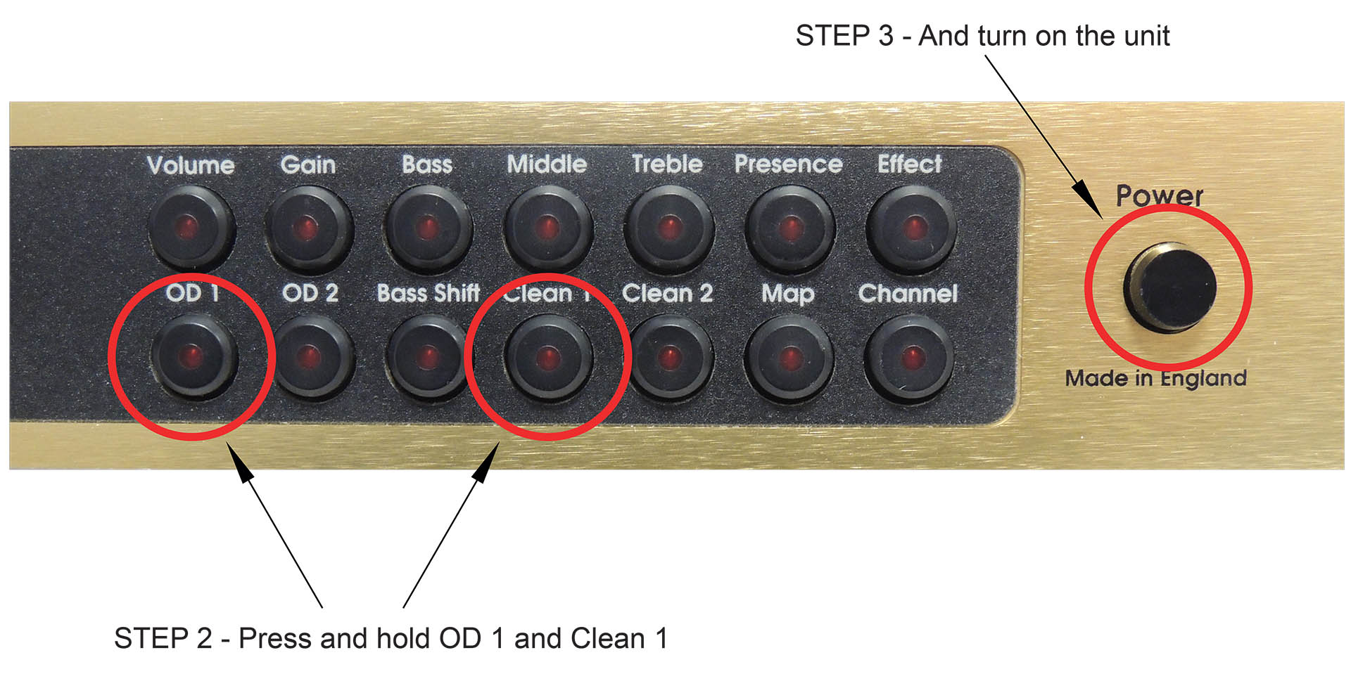
If you need to reinitialise your JMP-1, here's how:
Switch off JMP-1 via the power button on the far right.
Hold down the OD1 button and the CLEAN 1 button.
While holding down these buttons, switch on the JMP-1.
Wait a few seconds while the display flashes and then release the OD1 and CLEAN 1 buttons.
Now then, you're JMP-1 might NOT reset! Yes, that's right. If your machine is locked, performing a factory reset will be useless unless you unlock your JMP-1 first.
To check the memory protect status of your JMP-1, simply try to save a patch. If the display shows 'St L', then your JMP-1 is locked and you will need to unlock it prior to performing a factory reset.
Unlocking is simple. Just follow this procedure:
Try to save a patch.
While 'St L' is displayed, press the <CHANNEL> button.
The unit will unlock.
You can now perform a factory reset as above.
MARSHALL JMP-1 MEMORY BULK DUMP
While you're here, you may find it useful to know how to dump the entire memory of your JMP-1 to a sequencer or sysex package like MIDI-Ox or SEND-SX.
Just connect the MIDI OUT from your JMP-1 to the MIDI IN of your sequencer or computer's MIDI interface.
If using a computer, select that port in your sysex package.
Now just press <Patch> and <Volume> simultaneously on your JMP-1.
Being able to convey feel to the sound after the keys are played, can transform a performance into something quite unique and almost magical. Indeed, Roland was definitely on to something when aftertouch began appearing on it’s synthesisers in the mid-eighties. Today, many classic synthesisers have aftertouch strips that either don’t work or are a shadow of what they used to be. Almost forty years later, my modern FSR-based replacement aftertouch sensor for the Roland D-50, has considerably more dynamic range and is infinitely more reliable than the second-generation transducers that Roland originally used in the D-50 and transcends the instrument into another dimension.
CONFESSION TIME...
This post was launched on 14th July 2023 but now features my AT-D-50 Mk II which I released today on 1st May 2025. I decided to edit my original post as opposed to creating a new one, as I thought things would simply get confusing.
The latest revision of my AT-D-50 is not technically superior to my original design and functions in exactly the same way. There were however, some issues with my Mk I that I needed to address:
My original AT-D-50 was time-consuming and hence, expensive to make.
Packaging was expensive as the Mk I had to be shipped fully assembled and had to withstand transport all over the world.
It was also expensive to ship again, due to the fact that it was shipped fully assembled.
Unpacking and handling had to be done with care.
Installation was challenging. I never had any failures but I felt that things could be made easier.
I thought it was too expensive and I wanted to bring down the cost for my customers.
Last year, I was inspired to develop several peripherals for the Simmons SDS7. Long story short, I ended up investing in a 3D printer, specifically for 'printing' the internal packaging of one of those peripherals.
Well, I really got into the whole 3D printing thing and soon built up enough confidence to consider other projects, one of them being an idea for an AT-D-50 Mk II. Replacing the rubber platform of my original AT-D-50 with a series of plastic printed strips, could potentially address the issues listed above
Offering a replacement aftertouch sensor for the Roland D-50 in kit form which would comprise several FSR bed pieces on which two FSRs would be mounted, would be much quicker and simpler for me to prepare, easier and cheaper to ship, would pose much lower risk of failure during installation and would be about 25% cheaper.
The AT-D-50 comprises several components but the secret to its compactness is the 3D printed FSR bed sections. There are three identical strips and then the custom right-hand bed section.
After the success of my original designs which utilised two FSRs, I contacted several manufacturers but none were willing to supply me with bespoke single FSRs and so I had no option but to continue with my dual FSR configuration. This however, was a blessing in disguise. Had I been able to strike a deal and procure bespoke FSRs, I wouldn't have considered making things compact! That does mean that the AT-D-50 remains a dual FSR system.
Included with the AT-D-50 kit are a couple of strips which will help with accurate alignment of the FSR bed strips.
The FSR bed strips aren't just simple bits of plastic. At the back of each strip is a ledge so apart from the 'tools' that help accurately align the FSR bed strips relative to the keyboard chassis, it's easy to also accurately align the FSRs. Cool, eh?
Here you can see how the AT-D-50 is constructed. The key locators help with alignment of the FSR bed across the length of the keyboard while the rear ledge which is the same height as the FSRs, means that all you have to do is push the FSRs to the ledge for easy alignment.
My new AT-D-50 comprises three 'common' or universal FSR bed strips and a fourth FSR bed strip which is specific to the respective instrument, in this case, the Roland D-50.
The common FSR bed pieces are just under 220mm long. Although the actual FSRs are much longer, I'm still able to pack everything into something much smaller than my original bespoke shipping box. AT-D-50 Mk II is supplied with a few special plastic strips (tools) that make lining up the FSR bed much quicker, easier and reliable than my old rubber strip system.
SO LET'S TALK FSRS FOR A MINUTE...
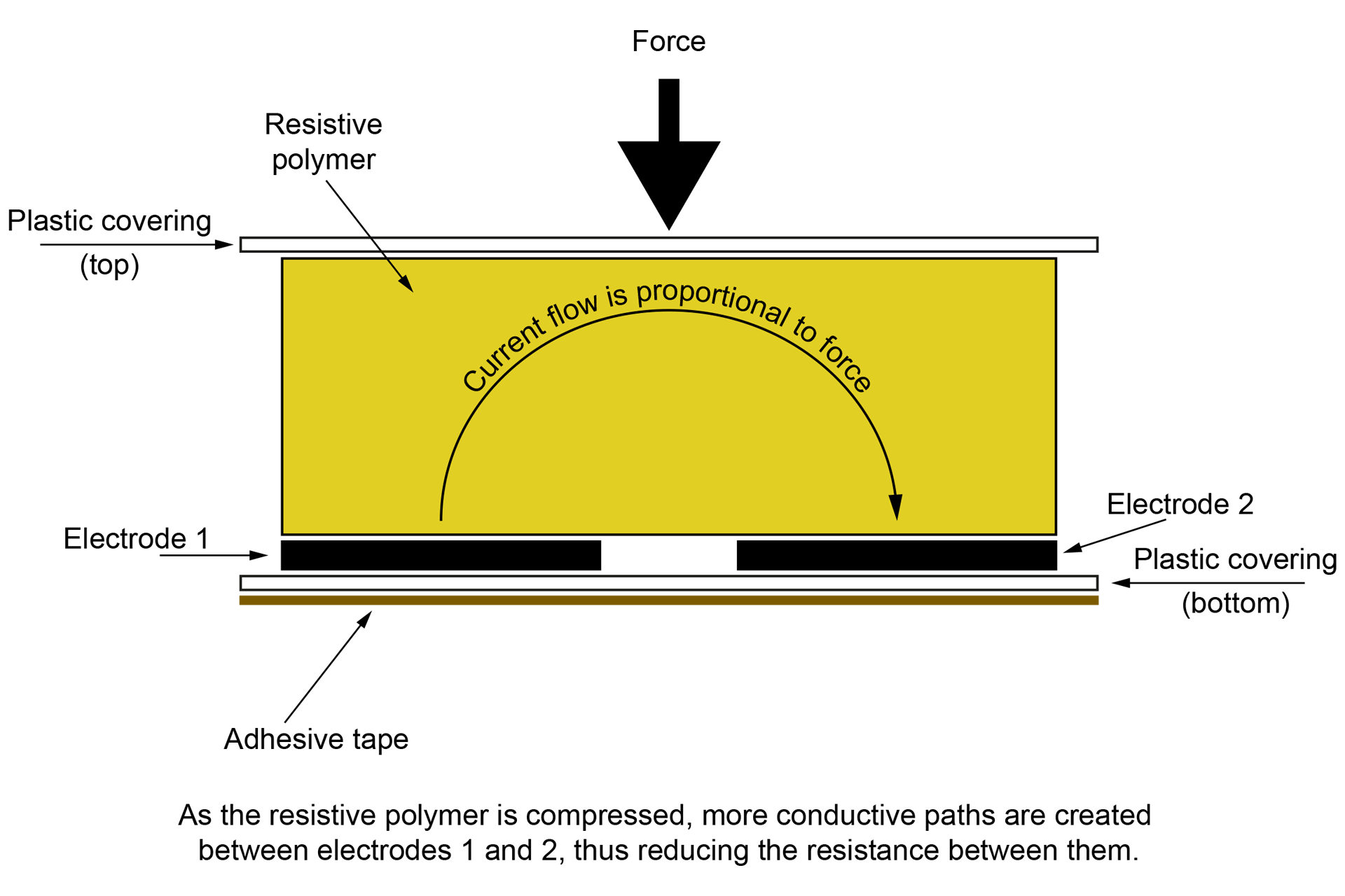
Being basically refined versions of the type of carbon-track sensors that Roland originally used but delivering higher dynamic range as well as other benefits, force sensitive resistors (FSRs) are perfect for this kind of application. In fact, modern aftertouch sensors and even some drum pads use FSRs. The principle is the same but the resistive polymer material is of a modern composition and the manufacturing process makes FSRs considerably more robust and reliable than previous pressure sensors.
Cross-section of a force sensitive resistor (FSR) illustrating how they work.
OKAY, BACK TO THE STORY...
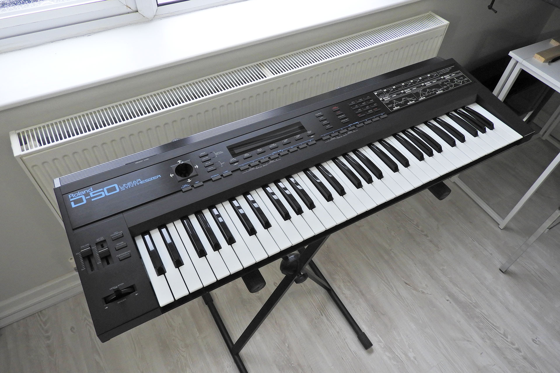
I get D-50s in all the time so I didn't have to wait too long for a customer to agree that I use their instrument as a test bed for my new design.
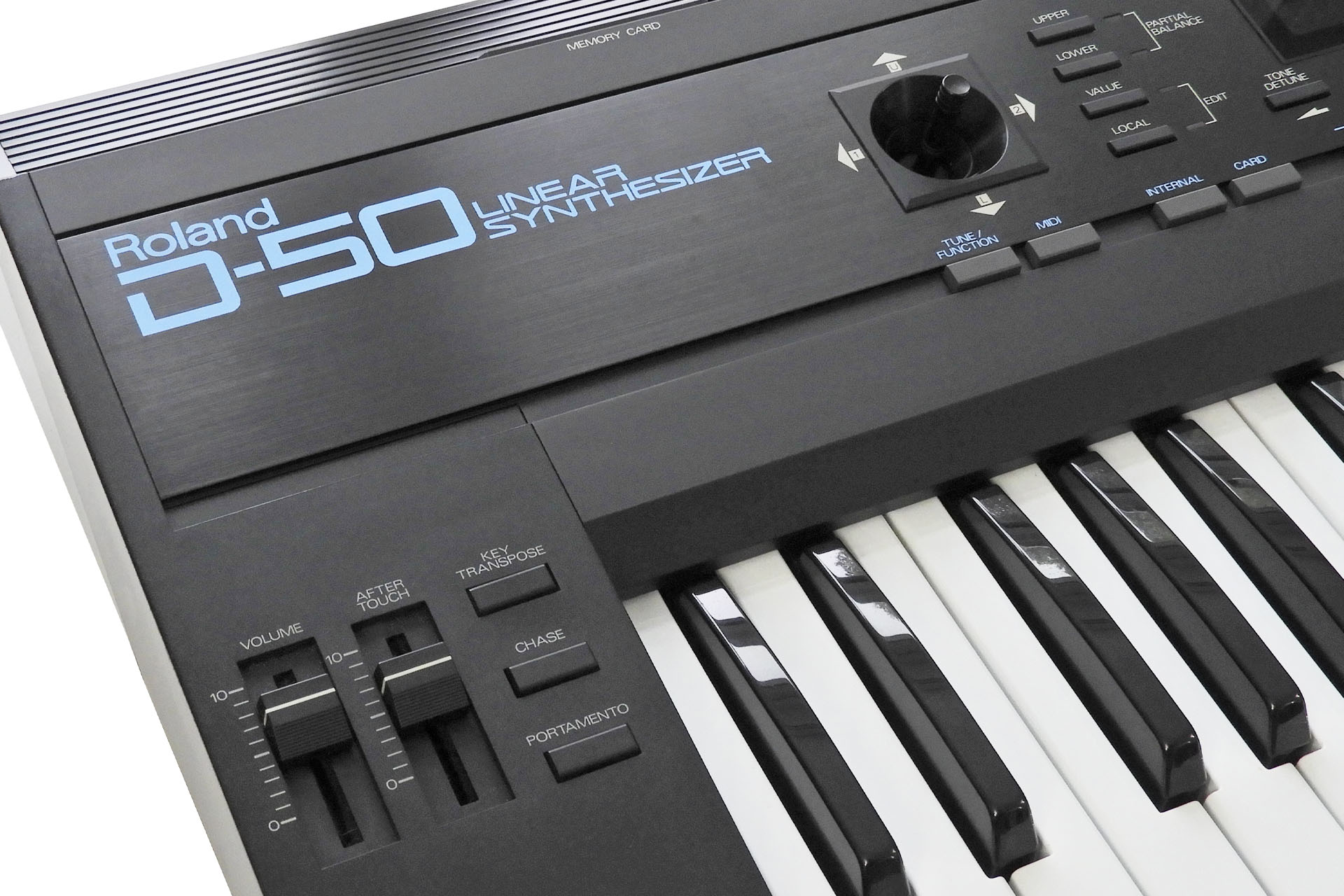
Here's the guinea pig for my AT-D-50 Mk II. An almost pristine example of this classic synth.
Being fundamentally the same as my original design, the only real difference with the new AT-D-50 Mk II is that the FSRs are mounted on several 3D printed strips of plastic instead of a single piece of rubber. The FSRs used are exactly the same. The way that pressure is transferred from the keys to the sensor is exactly the same and the signal sent to the D-50 is exactly the same. The AT-D-50 Mk II is just easier for me to make and ship, cheaper than the original and much easier for you to install.
The modular design approach makes installation quicker, easier and more reliable.
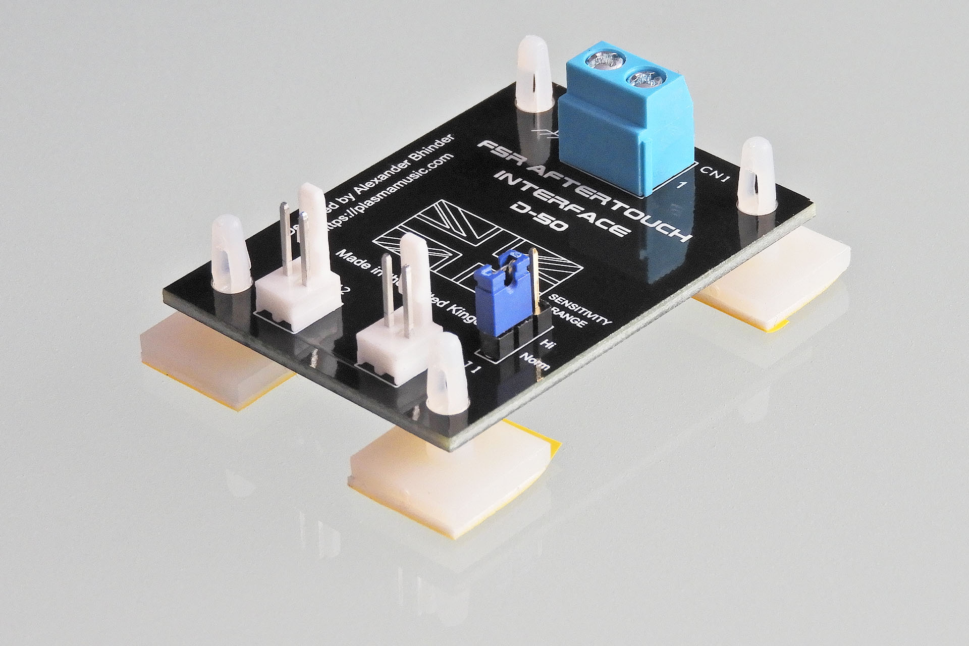
As mentioned and similar to my other FSR-based aftertouch sensors, my AT-D-50 replacement aftertouch sensor for the Roland D-50 comprises two FSRs. The terminals of each sensor are passively summed on a small PCB that I call a FSR Aftertouch Interface or FAI. Of course, FAI is supplied with my AT-D-50.
FSR Aftertouch Interface (FAI) PCB combines the outputs of each FSR and provides a simple way to select one of two sensitivity ranges.
The output from the FSR combination is quite different to the original carbon-track based system that Roland used in the eighties. FAI compensates for that difference but also offers something else...
FAI provides the facility to select one of two sensitivity ranges. Yes, that's right! What a cool little feature. 🙂 On top of that, the aftertouch control next to the volume control on the top of the D-50 still works as it did before.
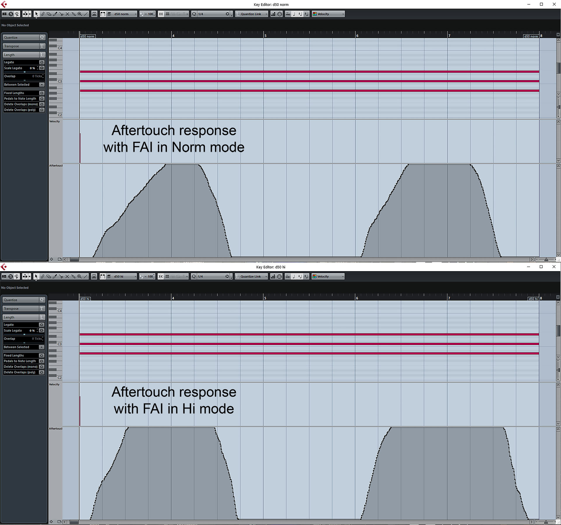
With the aftertouch fader on the D-50 set to about 80%, a MIDI velocity of about 90 and an average pressure, responses were recorded into Cubase with FAI in Norm and Hi modes. As you can see, a MIDI aftertouch value of 127 is reached in both modes. It's just that you get there quicker in hi mode.
Don't forget that you still have control over how aftertouch interacts with each sound within the patch settings.
FAI D-50 MIDI response in norm and hi modes
The 'upside-down' construction (as I call it) of the D-50, means that it's simply not practical to mount FAI to the bottom-case. With so little room on the inside of the top-case, FAI's four self-adhesive feet safely secure it to the inside of the D-50's left side-cheek. I've tried to make things as ergonomic as possible but of course the bottom-case has to be removed to access FAI. Positioning FAI on the inside left side-cheek however, does offer an excellent degree of access to FAI once you're in so switching aftertouch sensitivity ranges in the future, won't be too difficult.
FAI for the D-50 required a redesign of previous versions. Being side-mounted, I decided to use straight (vertical) Molex connectors, for example. It just makes life easier.
Also, up until FAI D-50, the facility to switch between two aftertouch sensitivity ranges was done by changing the value of the feedback resistor in the aftertouch buffer op-amp circuit. In FAI D-50 however, I decided to do the same job by switching the value of the series resistor between the FSRs and the op-amp.
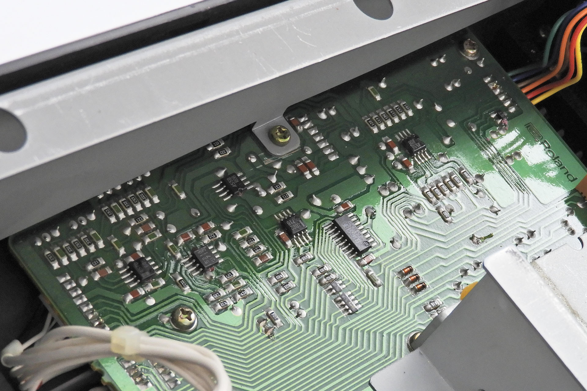
Remember I mentioned earlier that the D-50 has a lot of passive SMDs? Well one big bonus of adjusting aftertouch gain by varying the series resistor to the buffer op-amp, is that no components on the bender-board need to be replaced. In fact, the bender-board doesn't even need to be removed. All you need to do is solder a two wires to the bender-board.
The bender-board in the D-50 is packed with SMDs. FAI D-50 uniquely delivers the option of switchable aftertouch sensitivity ranges, without you having to touch them!
You've developed an FSR-based aftertouch sensor for one synth (in fact, three) and you think it would be easy to knock up an FSR-based aftertouch sensor for another. Hmmm... not quite. Each synthesiser has it's own challenges and I'm so glad I persevered with this project. I'm delighted that AT-D-50 not just works brilliantly but is now a system which can be installed by anyone with a little patience and technical competence.
I have to admit to being a bit puzzled as to why or how people tolerate an iconic instrument like the D-50, not having aftertouch. Imagine for a moment, that some keys weren't working or if your pitch-bend assembly packed up. Would you just accept it?
With an abundance of sensitivity and very high dynamic range, my replacement aftertouch sensor for the Roland D-50 truly gives this classic synthesiser, a whole new lease of life. It's like suddenly having velocity sensitivity! 😀 The added expression is just magical.
Modern FSRs are very reliable and it's not uncommon to see specifications quoting figures such as 'more than 10,000,000 actuations'. Being sealed units, FSRs are vulnerable to contaminants and oxidation problems like the old carbon-track sensors. It's no surprise then, that modern instruments that feature aftertouch, use FSRs. As previously mentioned, FSRs have a much greater dynamic range than their carbon-track counterparts which makes them ideal for modern drum pads.
I sometimes get asked to provide audio samples but I've backed off from doing that. Aftertouch isn't a sound, it's a feel. You don't 'hear' aftertouch. You hear the effect of aftertouch. So posting an audio file with no reference to how the synthesiser was played, just seems a bit pointless to me. What I can tell you, is that the feedback I've had from users who have installed my FSR systems is humbling and inspiring. For a couple of hundred bucks, it's really worth a shot.