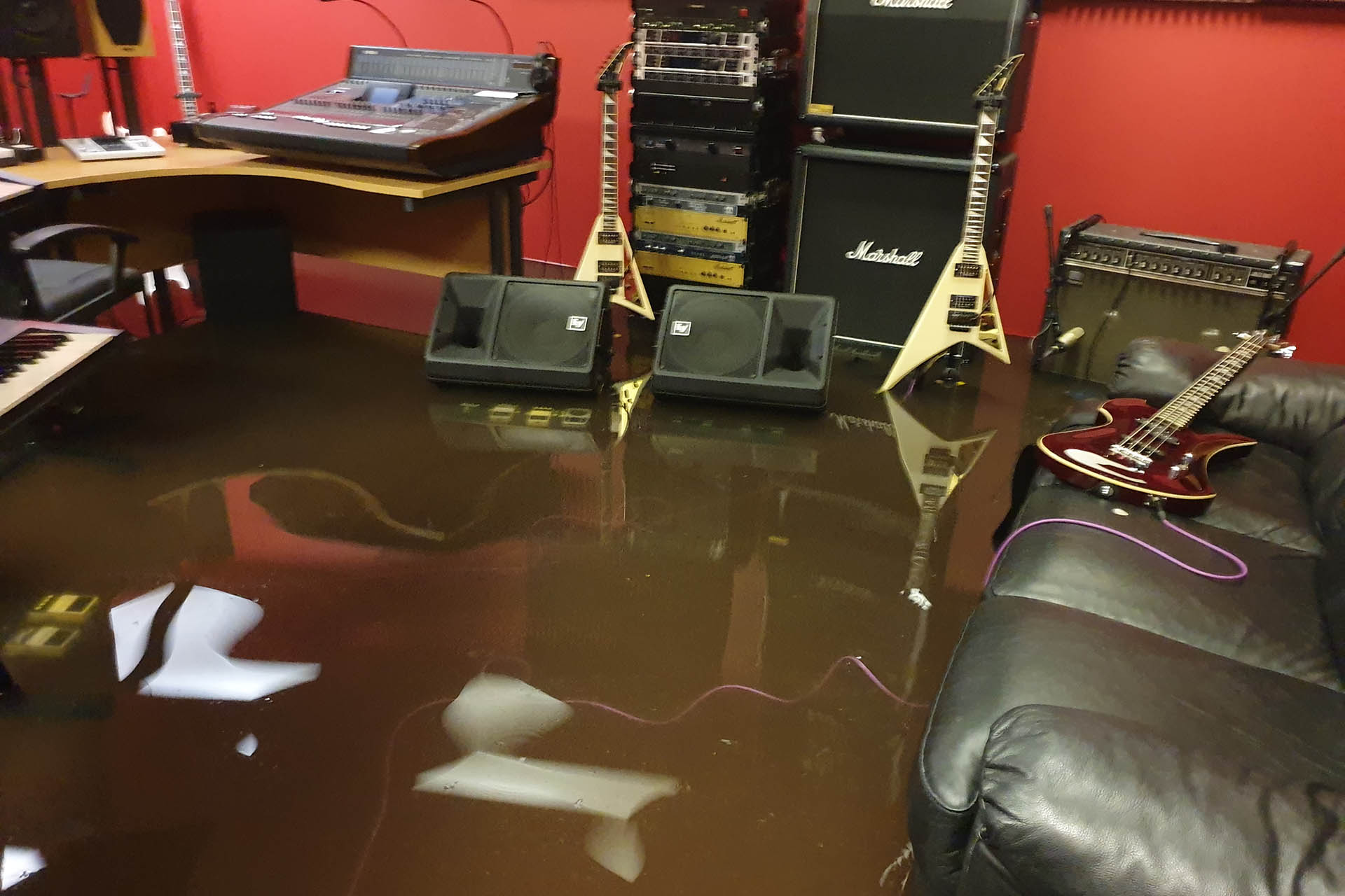
You can see my vintage 1979 Roland JC-120 took a hit as did my Marshall 1960B/V cab. I have another three of them around the place.
Probably every studio owners' worst nightmare...
Last Wednesday (12th August) at about 3:30 in the afternoon, we experienced heavy thunder and lightning accompanied by the most horrendous down-pour. I had popped out for a cigarette and the wind was seriously blowing. Then it went dark. I figured on making a dash home and swapping my cars over.
While at home, I received a phone call from Yvonne, the manager of BlueBox Storage Limited, Hemel Hempstead (where my studio is), requesting that I return as soon as possible. I grabbed a pair of wellies, while my heart sank as I just knew what had happened.
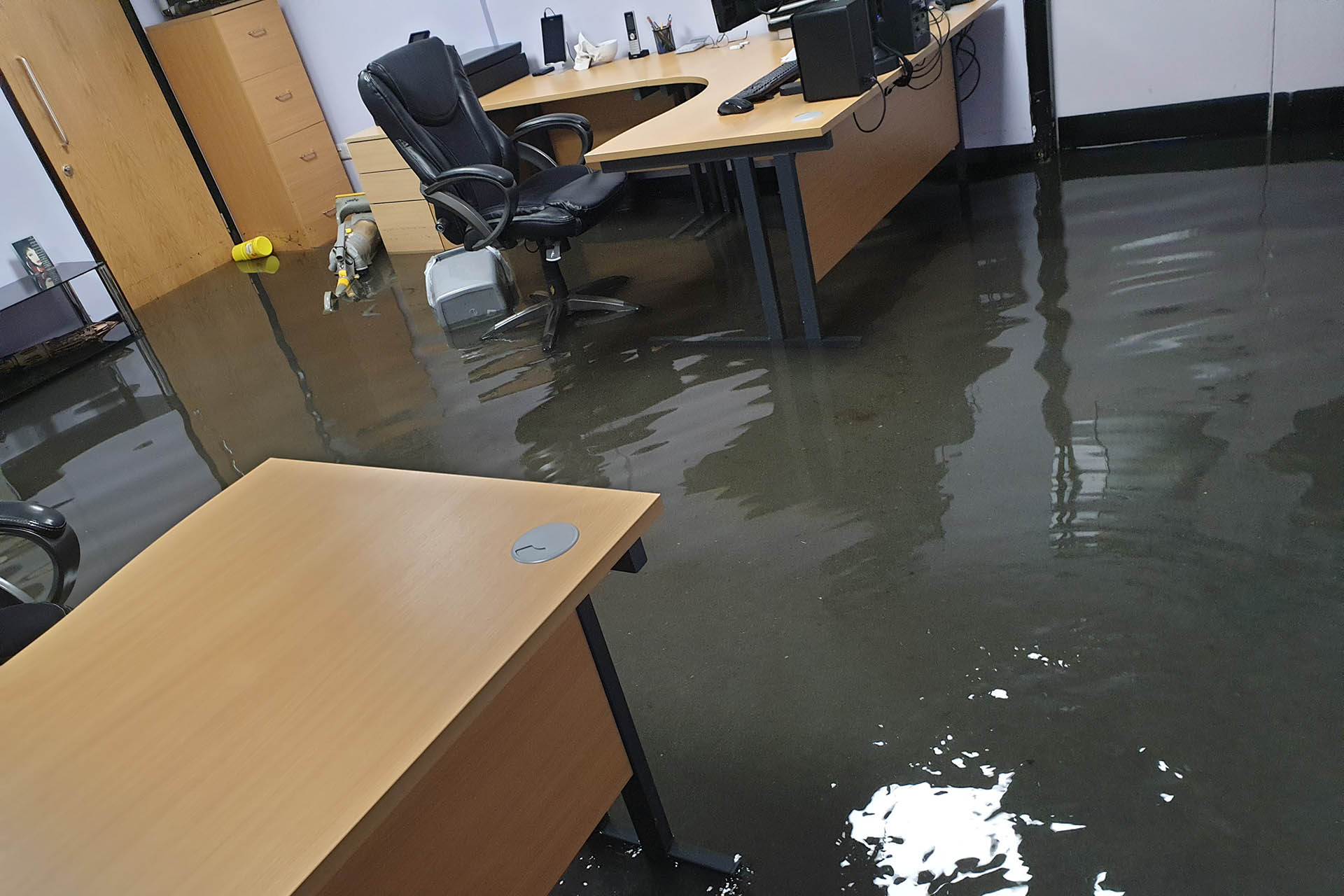
It was some time after 5:00 by the time I arrived at the BlueBox Stoage building and standing at the top of the steps leading down to the entrance of my studio, I was horrified to see the water gushing out of the building.
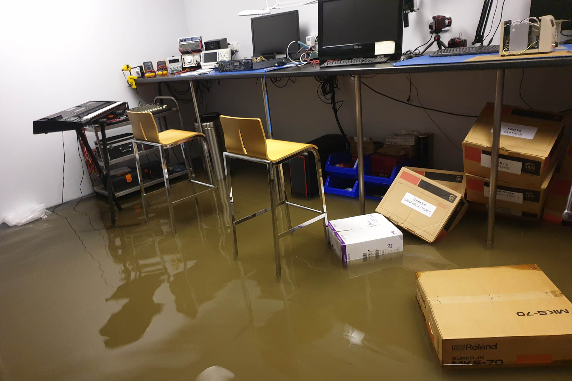
My lab got away lightly.
My vintage 1979 Roland JC-120, vintage 1969 Fender Vibro Champ, my collection of vintage pick-ups, my Marshall Silver Jubilee cabs, thousands of pounds worth of custom multi-cores and other cables, all hand-made and so, so much more that I haven't even seen yet, all gone in minutes.
I simply can't begin to properly convey my heart-break and sense of devastation but even now, I'm not sure if the gravity of it all has actually sunk in yet.
I'd just like to give out a big THANK YOU to my wife Julie, my daughter Tsunami, her boyfriend, Ayyaam and my friends Tony Burlinson, Adam King and Mike Barrett for responding so quickly and helping me move as much stuff to safety as quickly as possible. I think we got pretty much most of the studio gear out by the early hours of the next morning.
I'd also like to thank all of my Facebook friends for their kind words of sympathy and support.
I must also thank Yvonne Forecast and my landlords who were just so helpful and who responded really quickly. Dehumidifiers and outside storage began to arrive really quickly and a professional clean-up crew was organised.
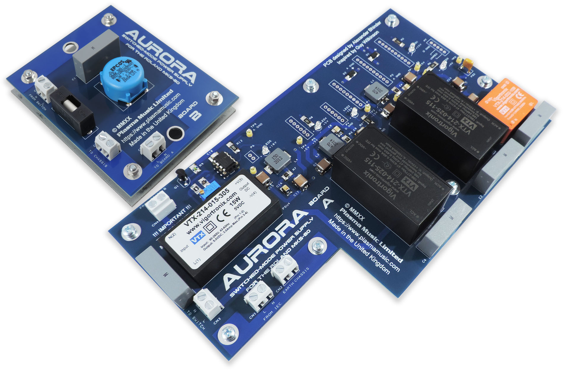
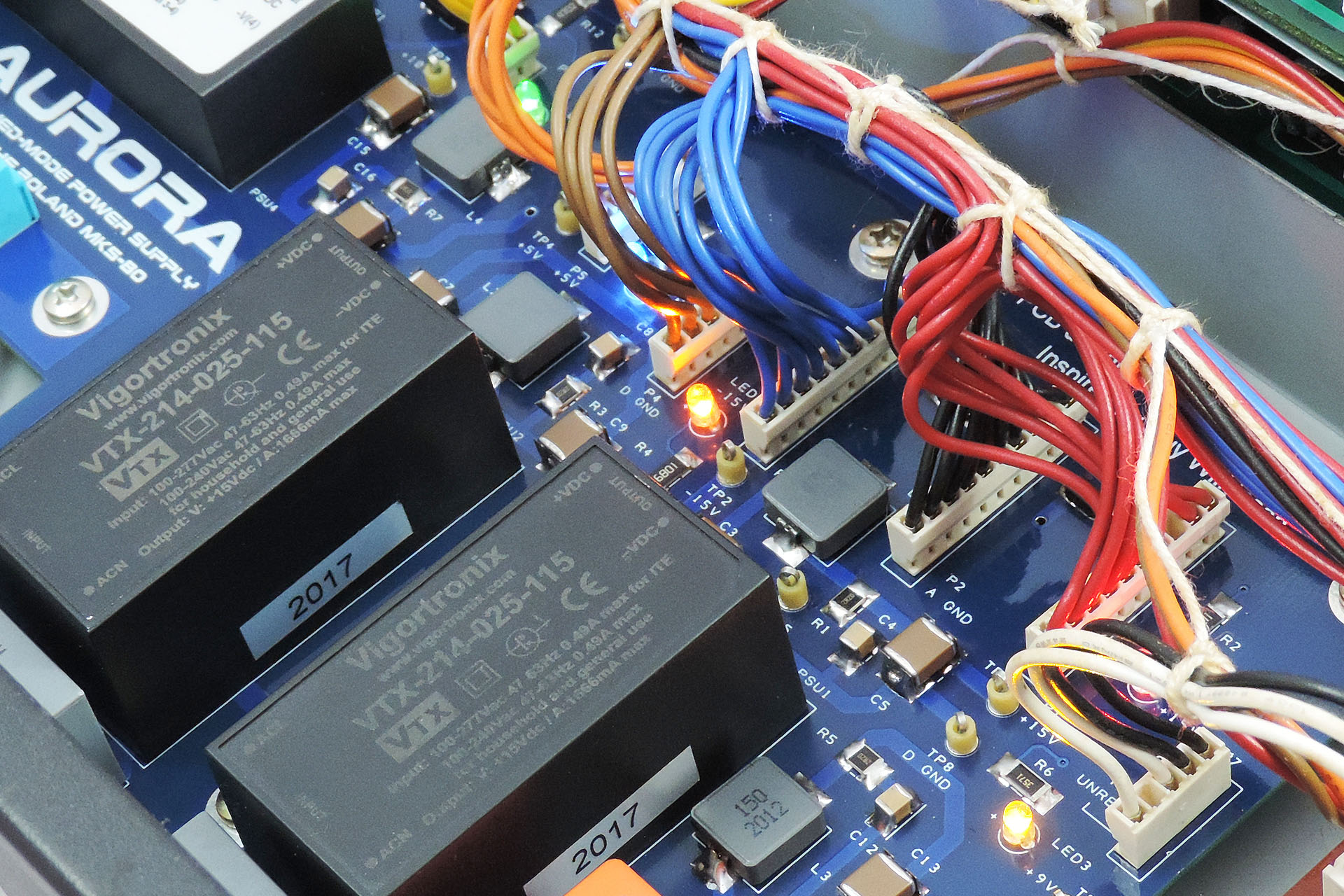
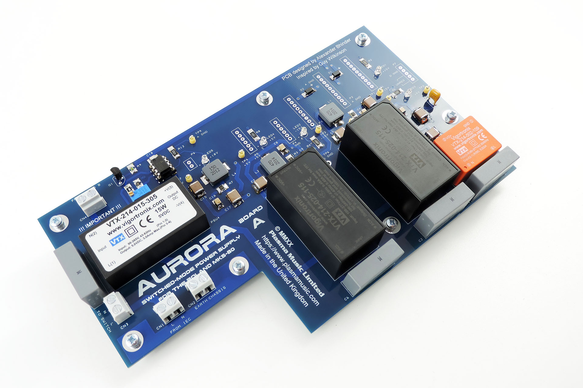
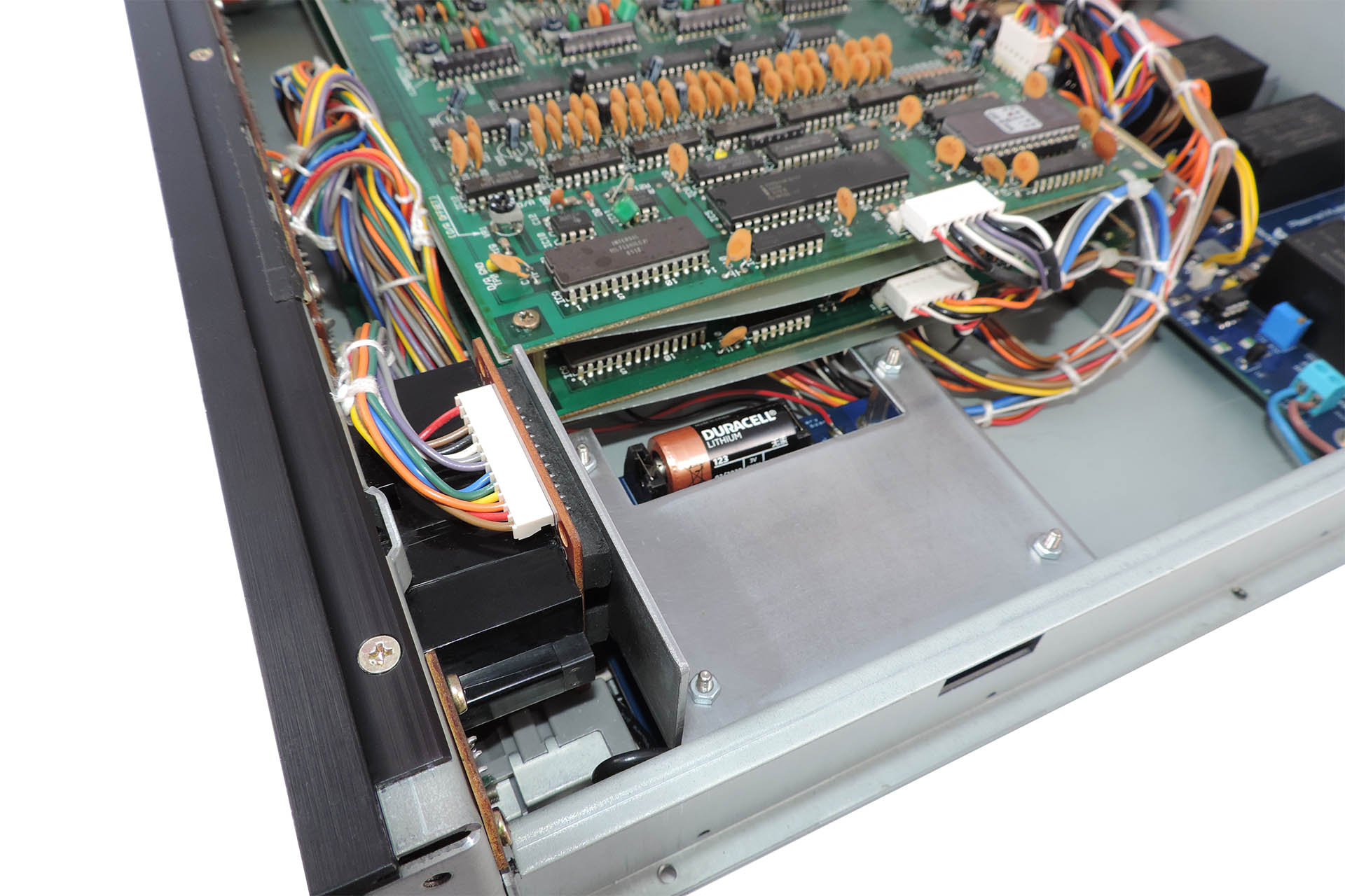
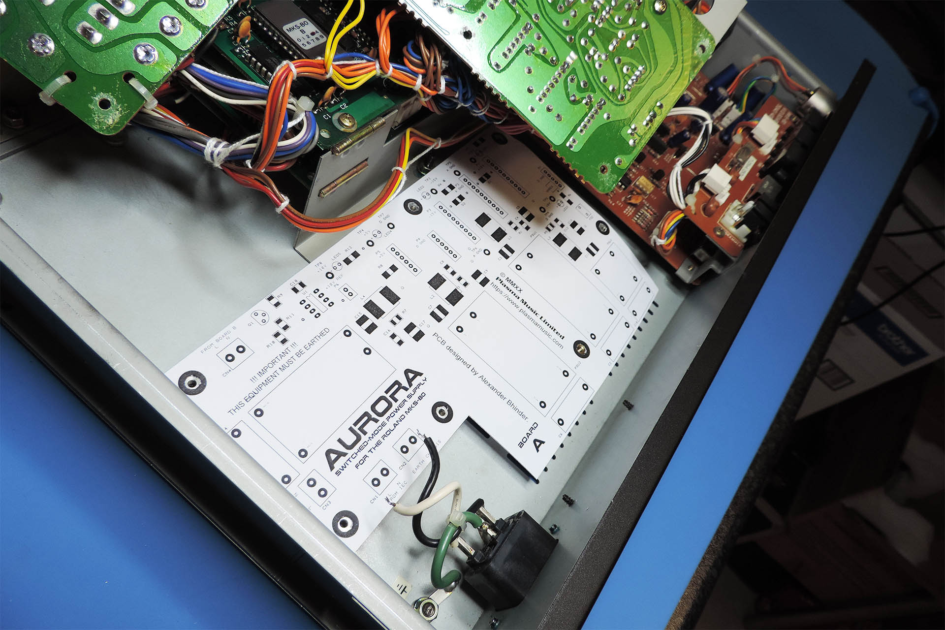
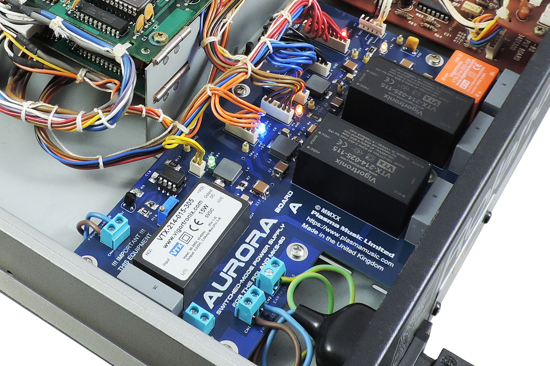
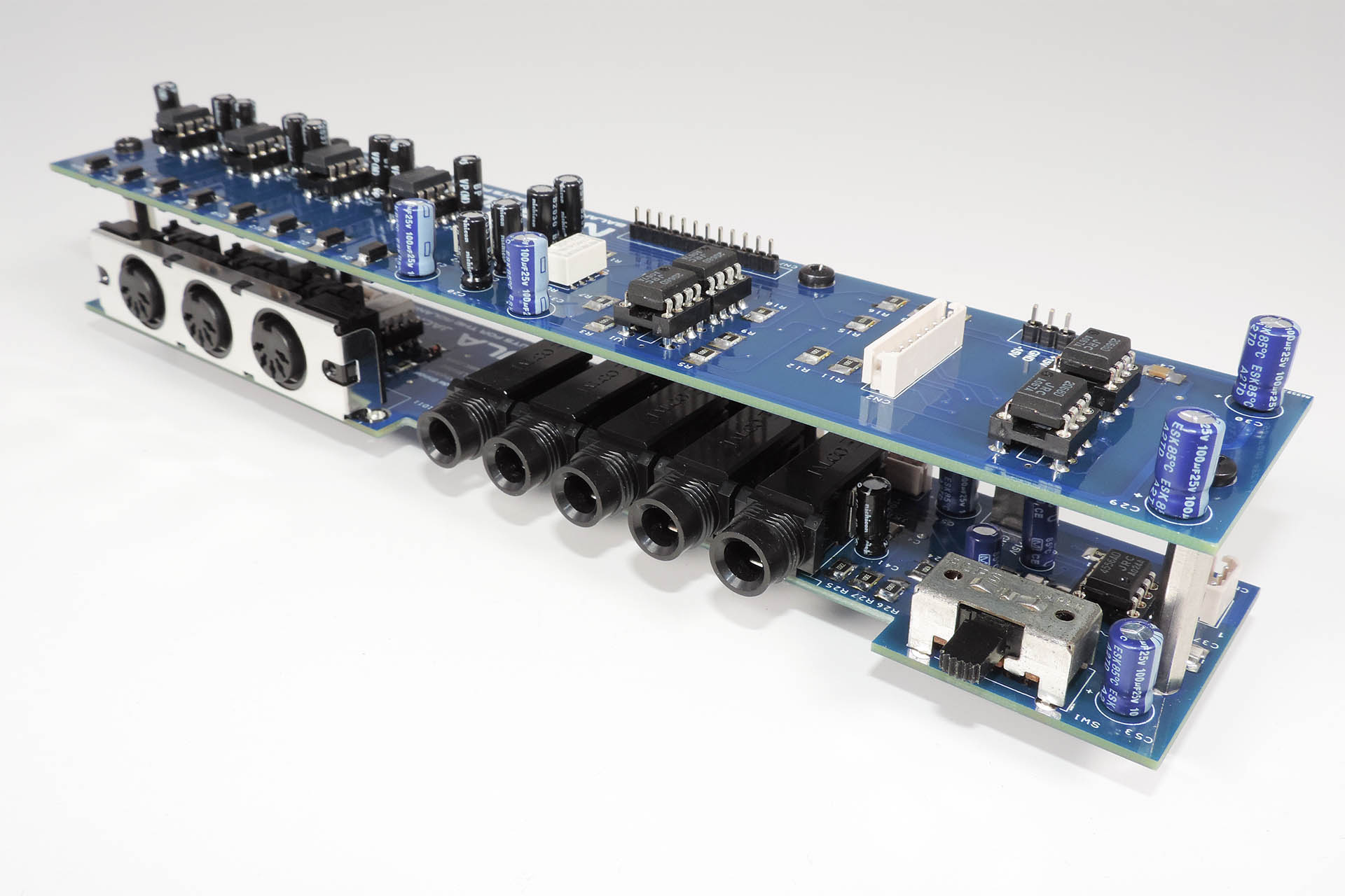
Aurora - the world's first replacement switched-mode power supply for the Roland MKS-80, shown here with the original Board B which was soon upgraded to Board Bx with on-board Live-Forever back-up battery mod.
The Roland MKS-80 is an amazing piece of equipment and a lovely sounding machine. As one of the last all-analogue-voiced synthesisers, I am hopeful that Aurora, a replacement power supply for the Roland MKS-80 will keep all of those gorgeous modules still left on the planet, working just a little longer.
Anyone who has a Roland MKS-80 with a power transformer that’s not native to their region, now has the option to upgrade the power supply in their machine and plug it straight into their mains supply, without the need of going through an external transformer.
If your Roland MKS-80 has a bad power supply or broken transformer, you now have the option to potentially bring it back to life. Also bear in mind that the old FR2 PCBs are now very brittle and prone to dry joints and even cracking.
At the time of writing, some Roland MKS-80s have been operating for thirty-six years! While designed extremely well, the power supplies are stressed systems (as in any machine) and the last thing any MKS-80 owner wants is for the power supply in their machine to go south. IC1 on the original PSU for example, is a M5218L. It's a crucial part of the +5V supply and the 10V reference circuit. If this packs up, the +5V rail could rise to values that could seriously damage your MKS-80 and even make it unrepairable. As time goes on, the likelihood of this happening, only increases. The +/-15V supplies which drive the voice boards, are a little more robustly designed.
Electronics in general doesn’t like heat. Aurora runs much cooler than the equivalent linear power supply.
Over time, your MKS-80 may develop transformer born hum. This can't be 'filtered' out and you're kinda stuck unless you can acquire a replacement transformer. Hey, you're in luck 'cos Aurora doesn't produce any hum!
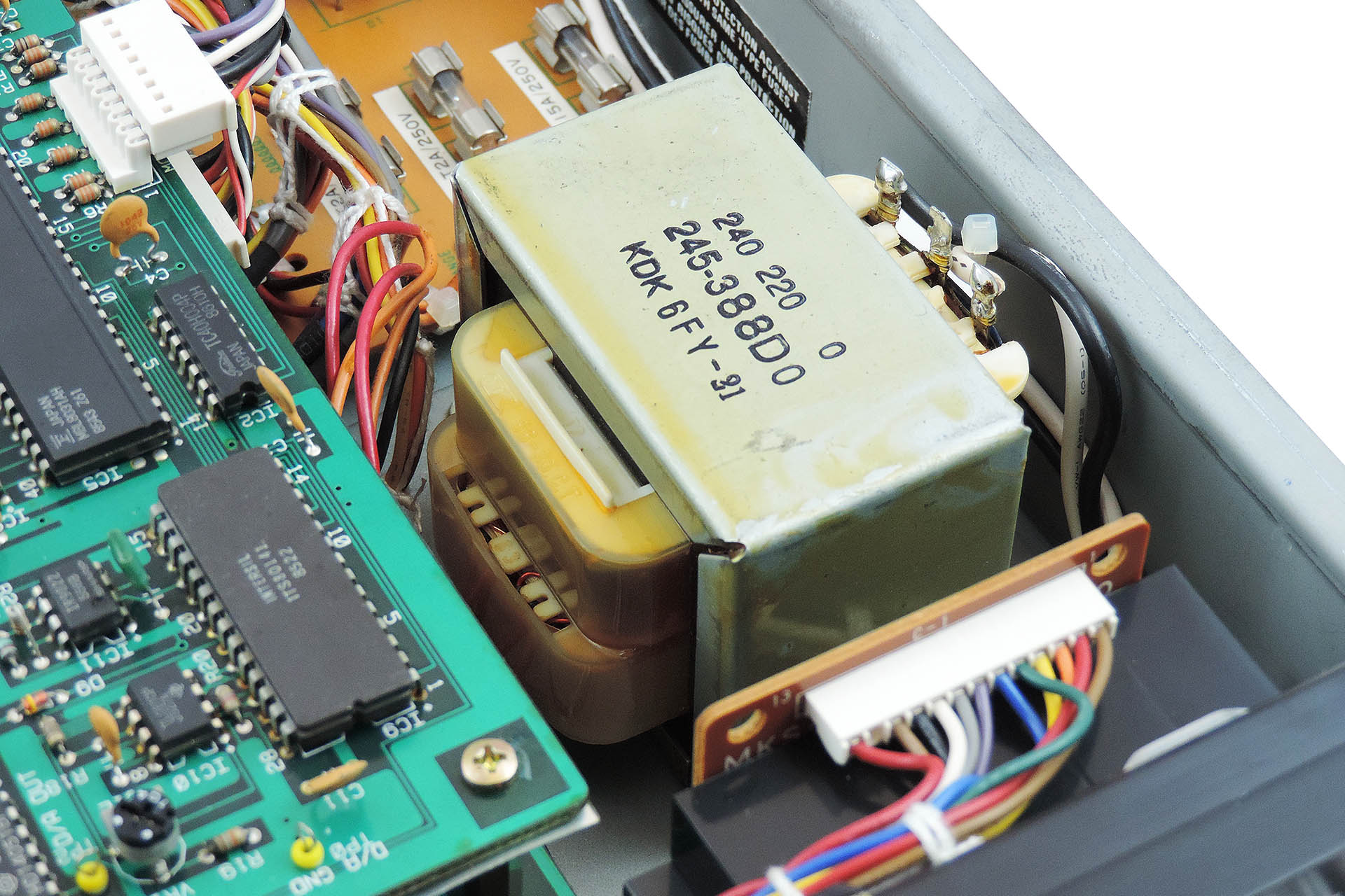
Here's the transformer in a Roland MKS-80. After a couple of decades, they can develop hum.
Originally, Aurora was going to copy the footprint of the original MKS-80 power supply. A single L-shaped board however, would have meant a lot of wastage and potentially necessitate the removal of the front panel to replace the original mains wiring which would have been too short to reach the single PCB.
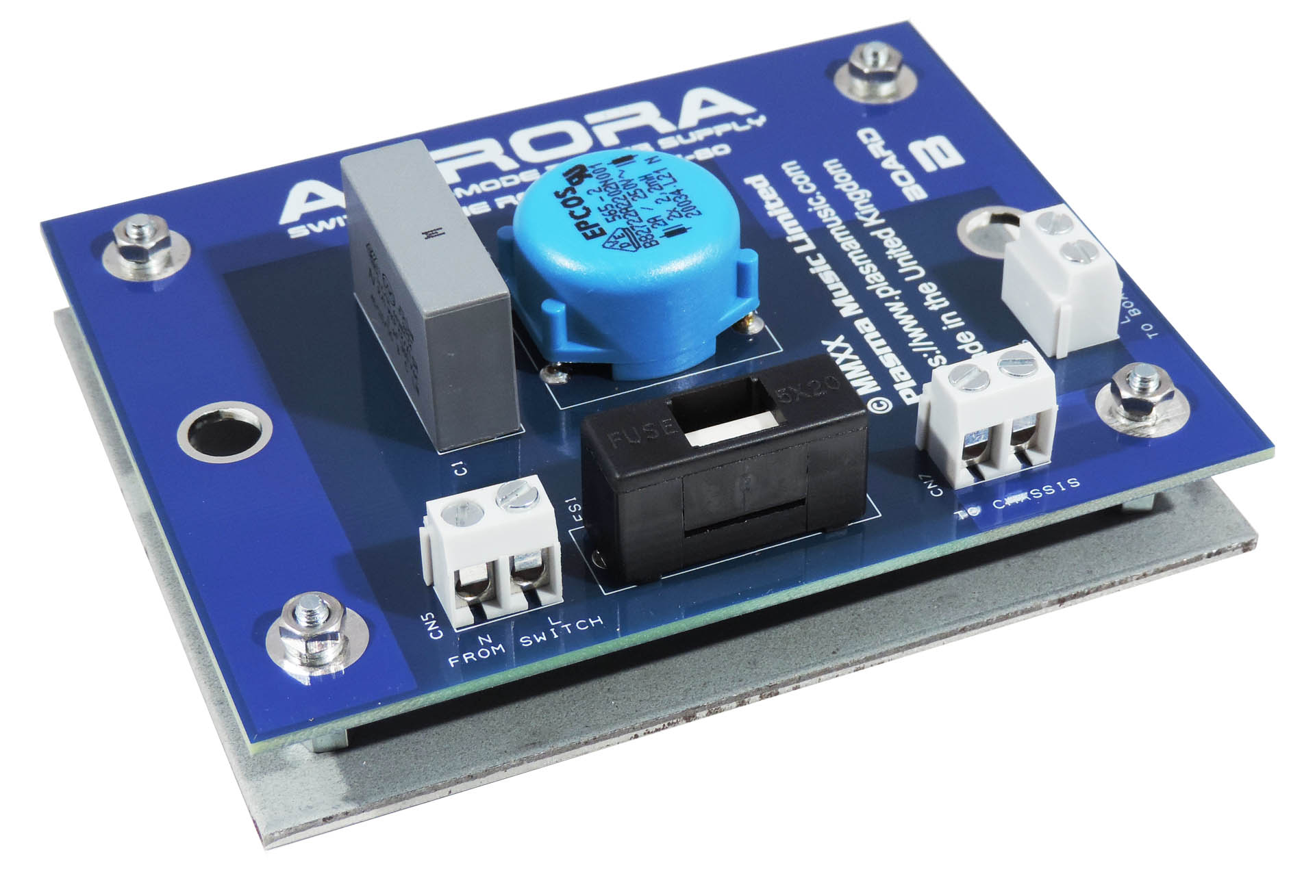
The solution was to split Aurora into two PCBs; Board A being the main part of the power supply and Board B taking care of mains protection and filtering.
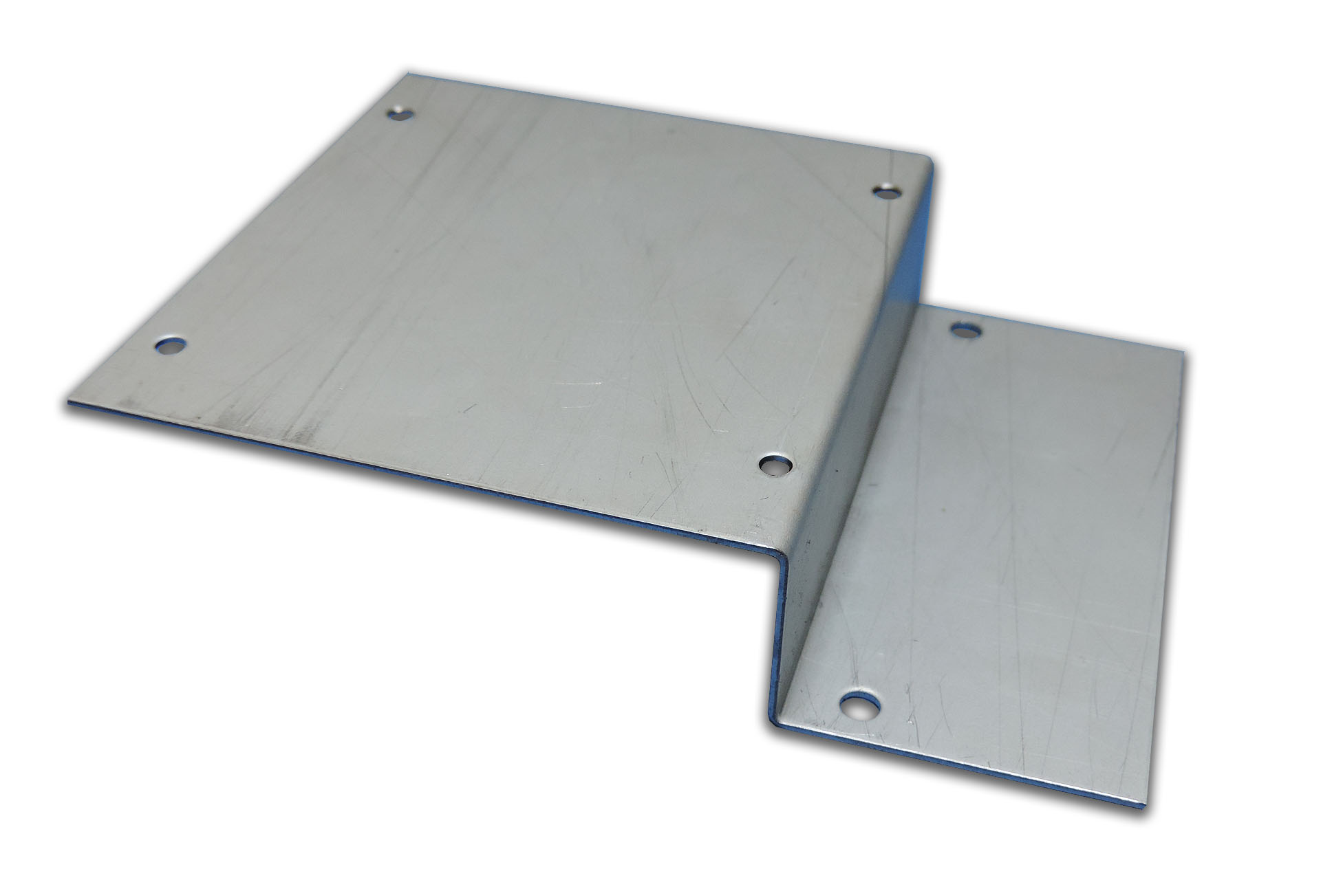
Aurora Board B sits my V01 mounting bracket. This occupies the space previously taken by the transformer.
I made use of the reinforcing plate that's underneath the original transformer. The size of board B is the same size as this plate. I simply added four M3 mounting holes and christened it V01, LOL. Whatever, this all provides for a very tidy and cost-effective solution that requires minimal reworking of existing wires, etc.
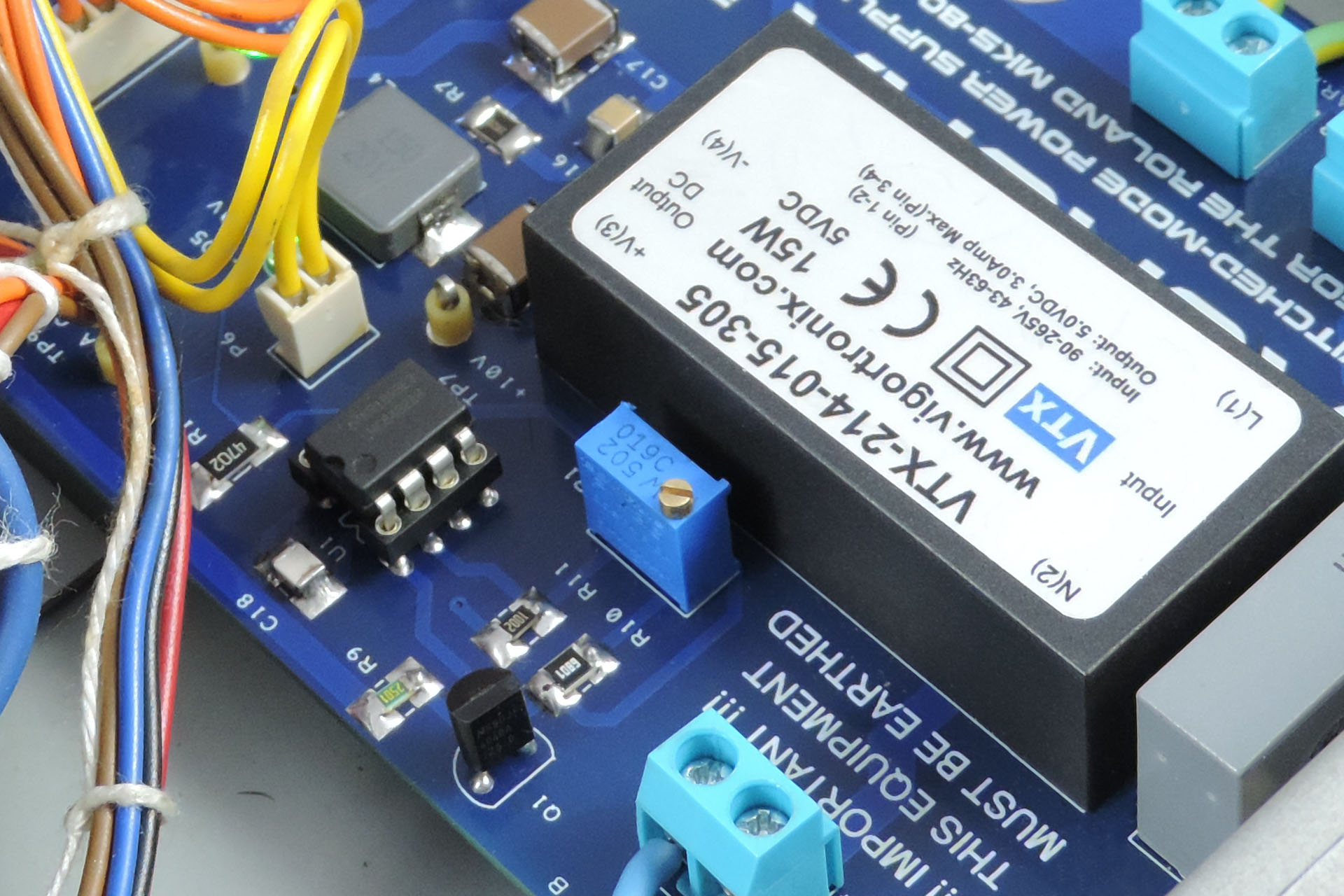
Aurora's 10V reference source started out as a precision circuit using tight tolerance components and a high-grade op-amp. The results were impressive but later, I changed the design and incorporated a multi-turn trimmer so as to allow for adjustment of the reference which may result from component drift over time.
Adjustment of Aurora's 10V reference, allows for compensation of component drift over time.
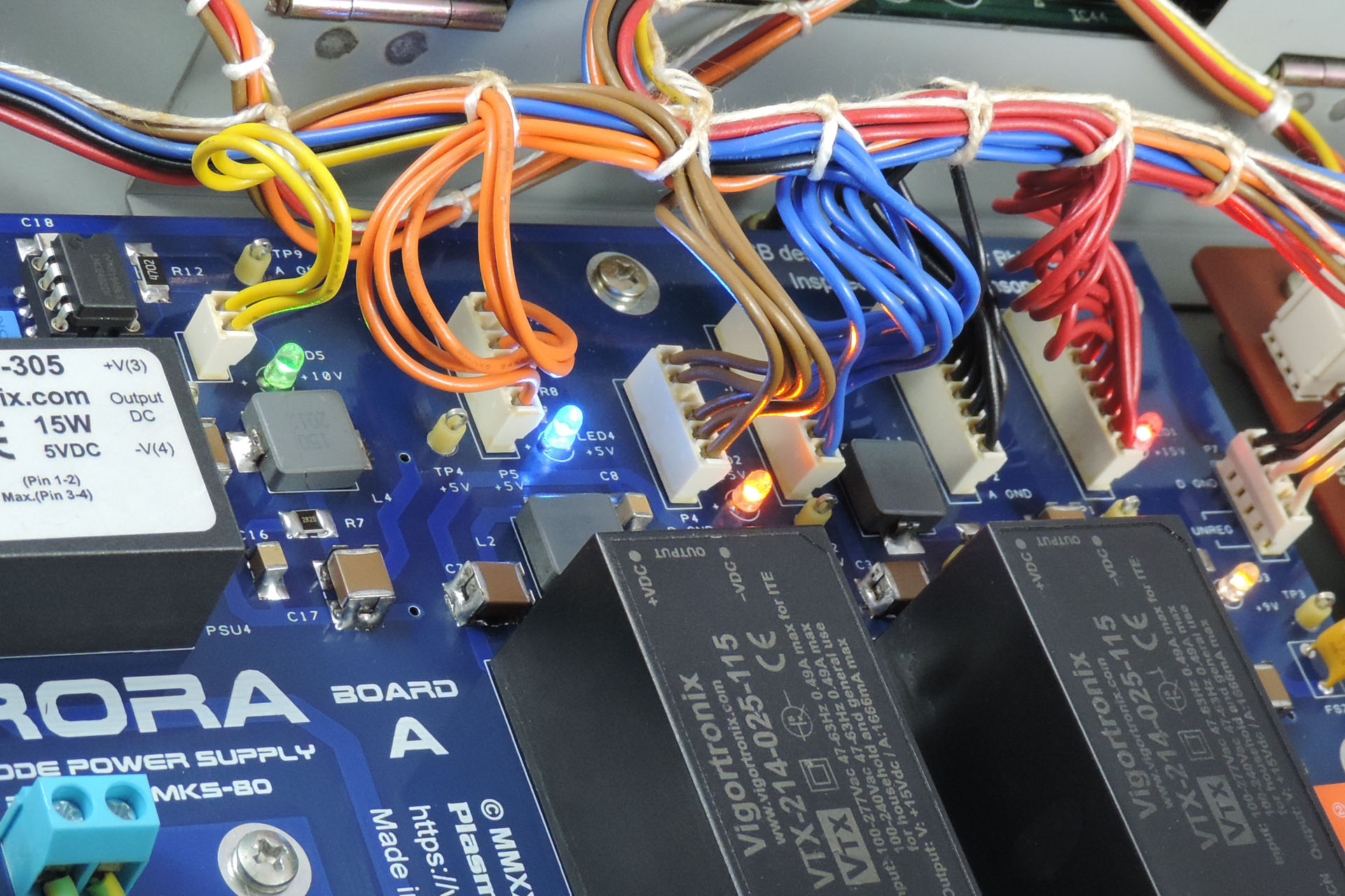
Each supply has it's own status LED. I thought this would be a nice addition and in keeping with the original design although unlike the original, Aurora has a different coloured LED for each supply, including the 10V reference.
Also note the test points allowing for easy checking of all voltages.
Aurora has individual power rail status indicators (LEDs) and conveniently placed test points.
So I was going to teach myself Arabic or Mandarin during lock-down 2020 but instead, I kind of decided to design this. It just seemed like a really cool thing to do! 😀 😎
You can read about the development of Aurora Replacement Power Supply for the Roland MKS-80here.
INSTALLING AURORA
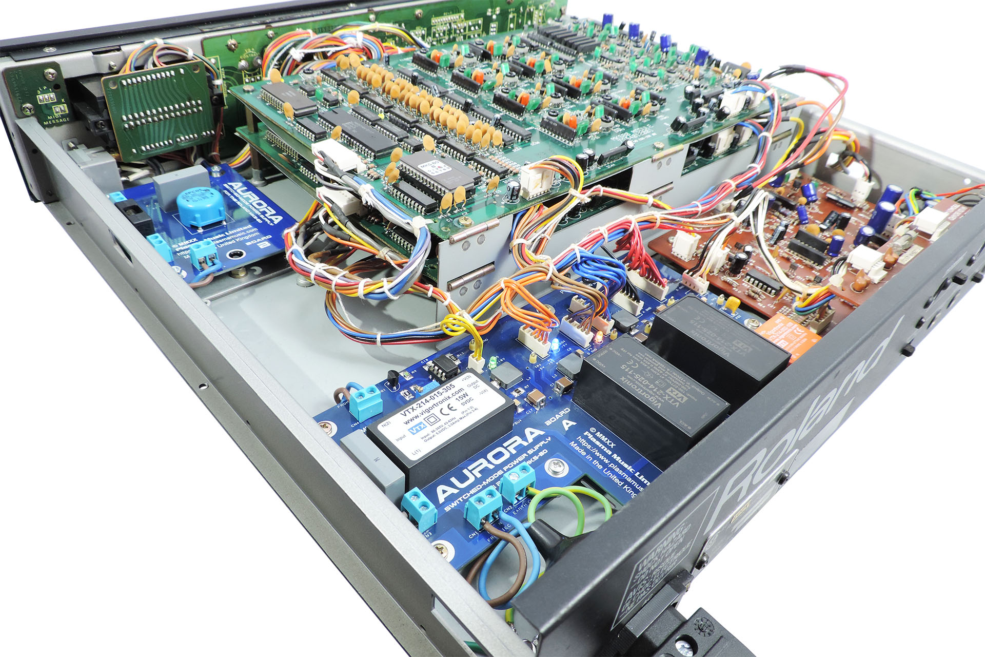
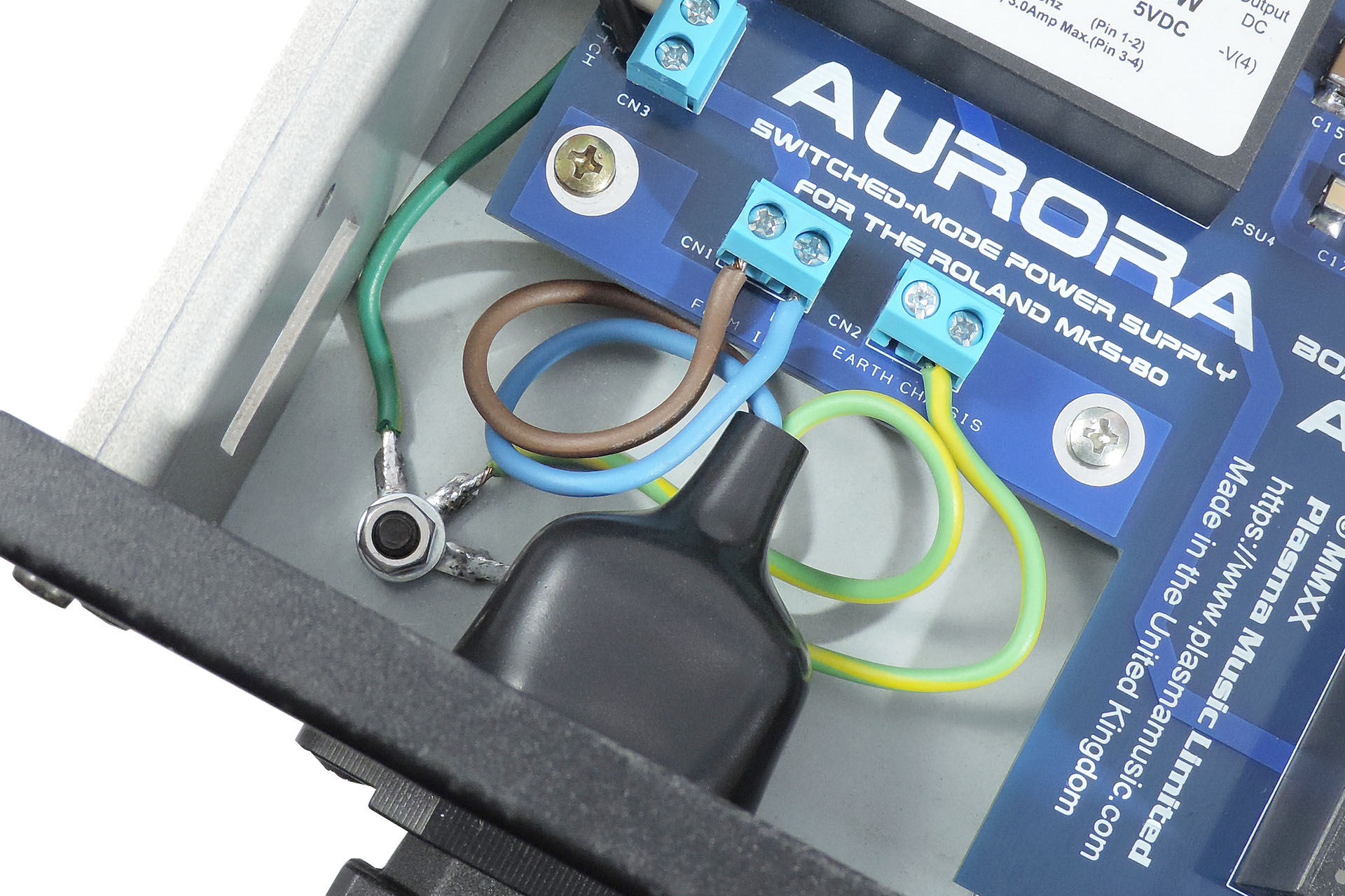
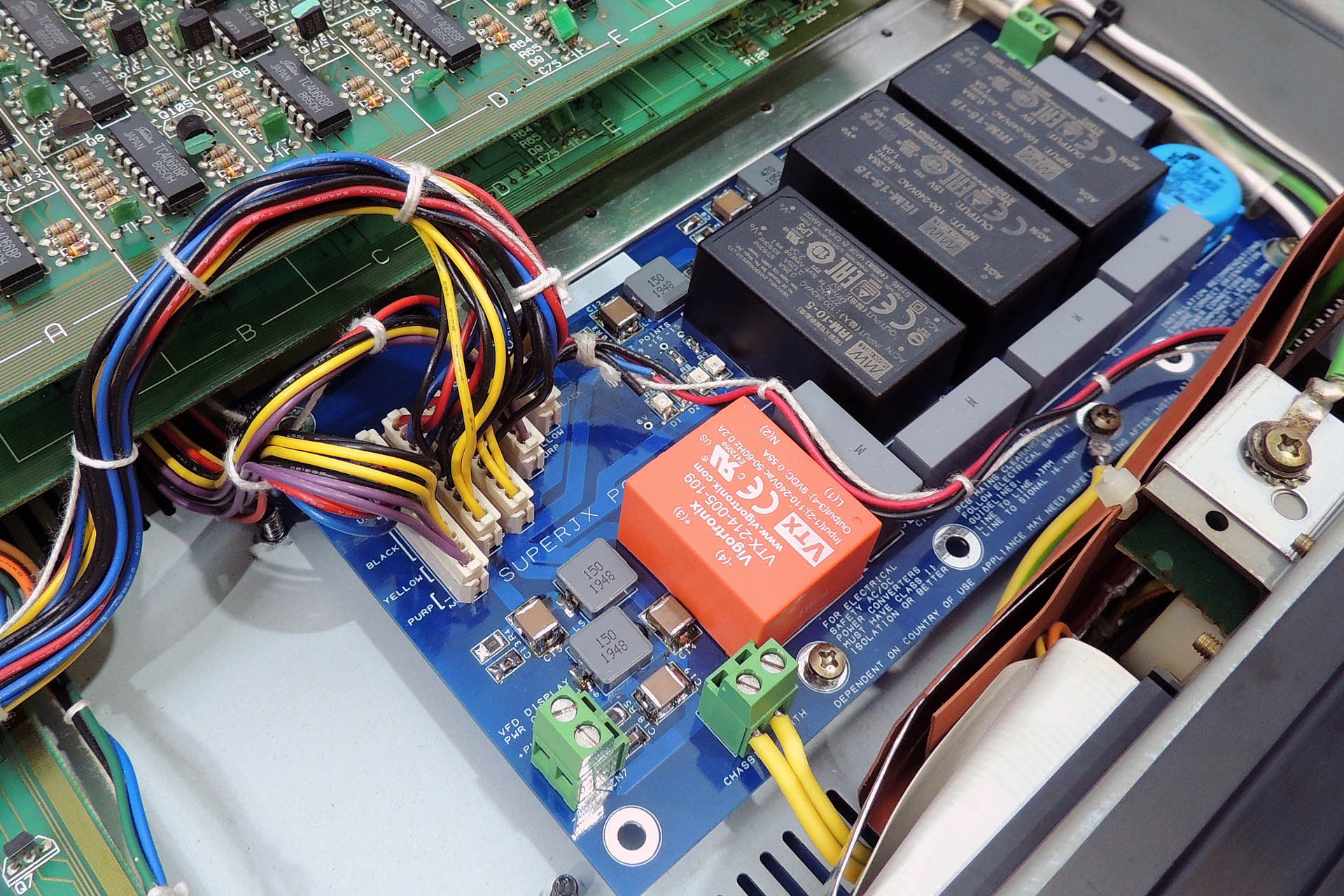
Keep cabling neat and tidy.
Installing the Aurora boards requires a certain degree of knowledge, experience and skill. I therefore insist that the installation be performed by a suitably qualified technician. Aurora is a power supply that converts mains voltage to several DC voltages that your machine requires. Safety is paramount and although fully tested prior to shipping, I strongly recommend that you test Aurora outside of your machine prior to installation. Since there is mains voltage on both boards, care should be taken that the boards are lifted clear of any work surface during such testing, using for example, PCB stand-offs (spacers).
Removing the original power supply including the transformer also requires a certain degree of knowledge, experience and skill. Remember that these machines are over thirty years to over thirty-five years old.
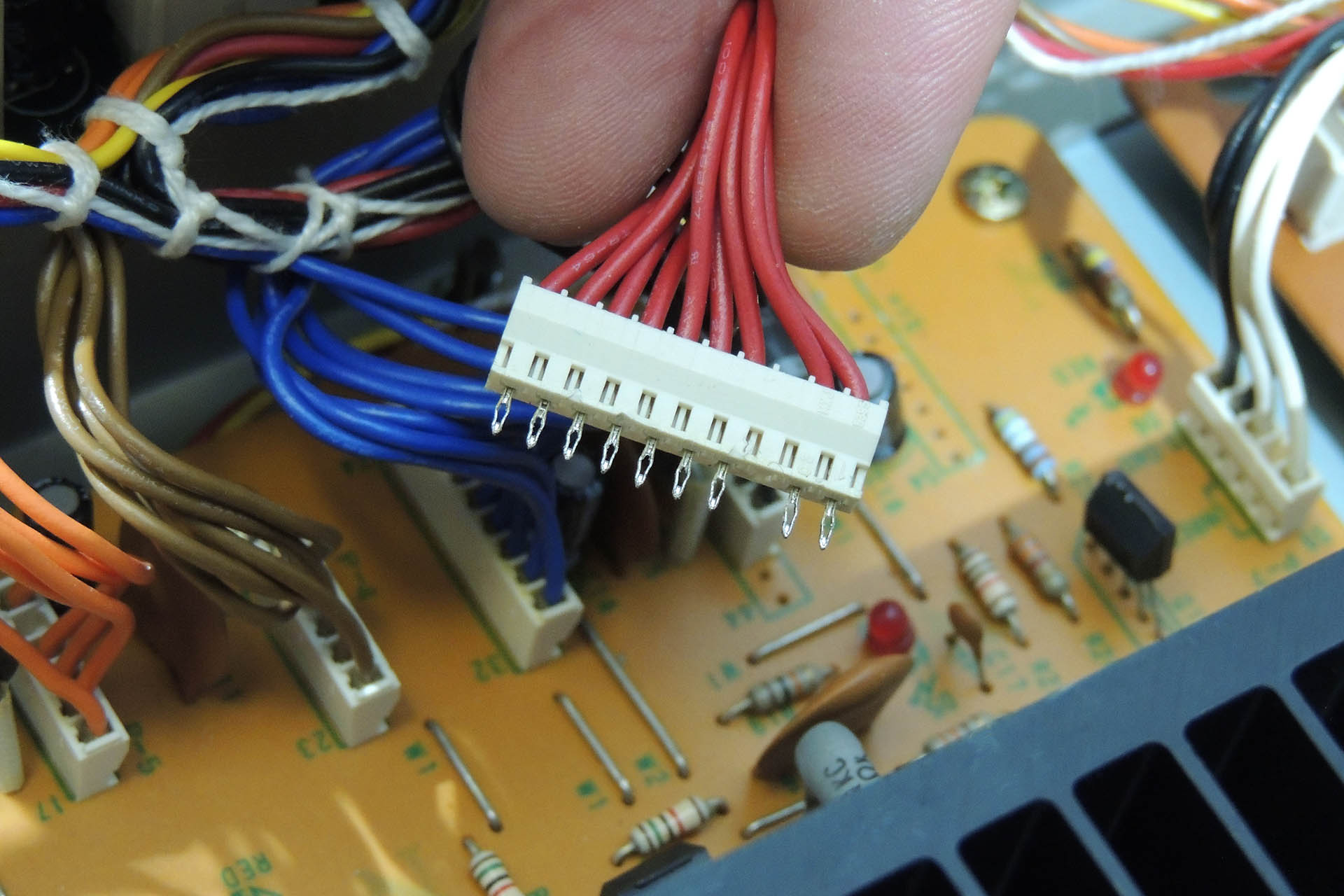
The voltage distribution headers for example, are soldered to the board. The pins on the headers are not conventional straight pins. They're arrowheads and have a tight fit. Once you're confident that you've removed all of the solder, gently prize them off the board (GENTLY). I suggest that you wiggle the connector from the component side while observing the underneath so as to ensure that all pins are indeed free.
+15 V header on MKS-80 power supply showing hollow 'arrowhead' pins.
Don't simply cut the wires to the transformer and the terminals on the original power supply board. Instead, try to unwrap so as to preserve the original length of wire. You may trim some of these later but you don't want to be left short!
Require tools and equipment are as follows:
Temperature controlled soldering station (e.g. Weller WE1010)
Temperature controlled de-soldering station (e.g. Duratool D00672)
Small wire cutters
Small pointed pliers
Adjustable cable strippers
Set of cross-head screwdrivers
Small flat-head screwdriver
Set of box-spanners (metric)
Tweezers
Digital multi-meter (DMM)
PLEASE don't use a plumber's or electrician's soldering iron and please don't use a manual solder pump. You'll just wreck things. In fact, if you're thinking of using that kind of equipment, you shouldn't be operating on your MKS-80, let alone installing Aurora!
Finally Aurora is up and running... beautifully.
A few hints on workflow:
Do NOTrush it! Take your time.
Check and double check your work after each stage.
Do not rely on the status LEDs as indicators of required voltages. Use the test points to measure the voltages with a DMM.
When removing screws and nuts from your MKS-80, use a 'gently, gently' approach. You really don't want studs to loosen or threading to shear.
Do NOTover-tighten screws and nuts. You're dropping a replacement power supply into a vintage synth module and not building a spaceship that's destined for the outer planets!
The 10V reference has been set by me using a regularly calibrated DMM. Please do not mess with it!!!!!
Note the orientation of the headers before you remove them. It's actually not too important other than to keep things tidy except... for P7. Unlike the other headers which each carry a single supply, P7 carries the 9V supply and a digital ground, to the programmer (MPG-80) port via the output board. It's VERY important that this connector's original orientation is maintained.
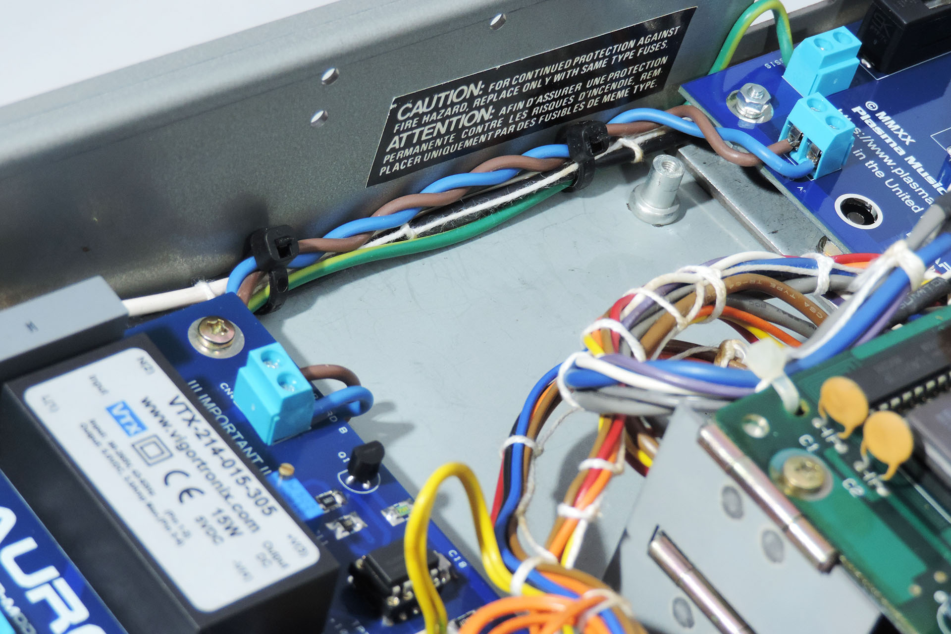
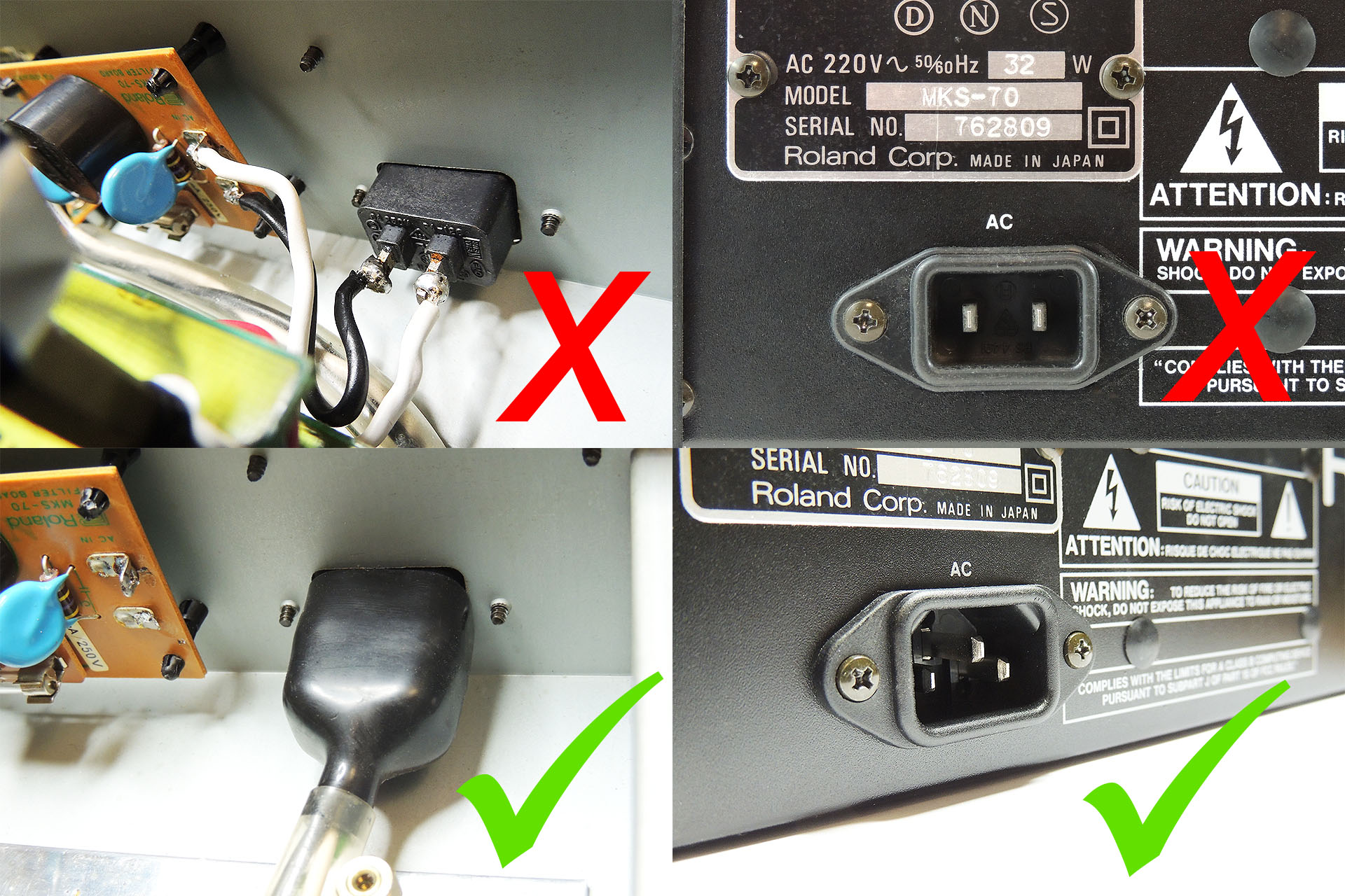
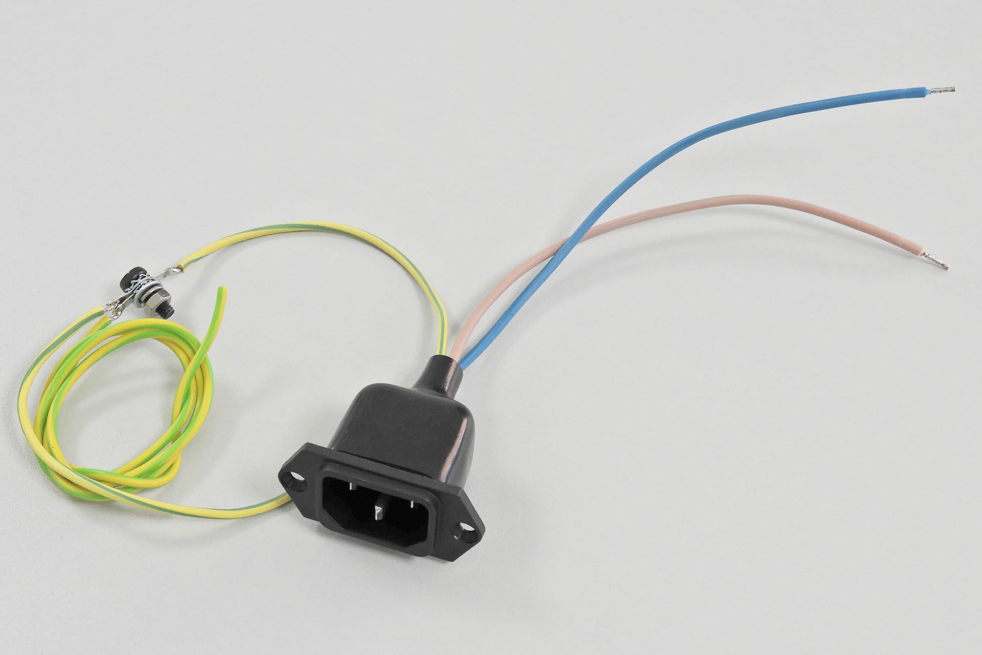
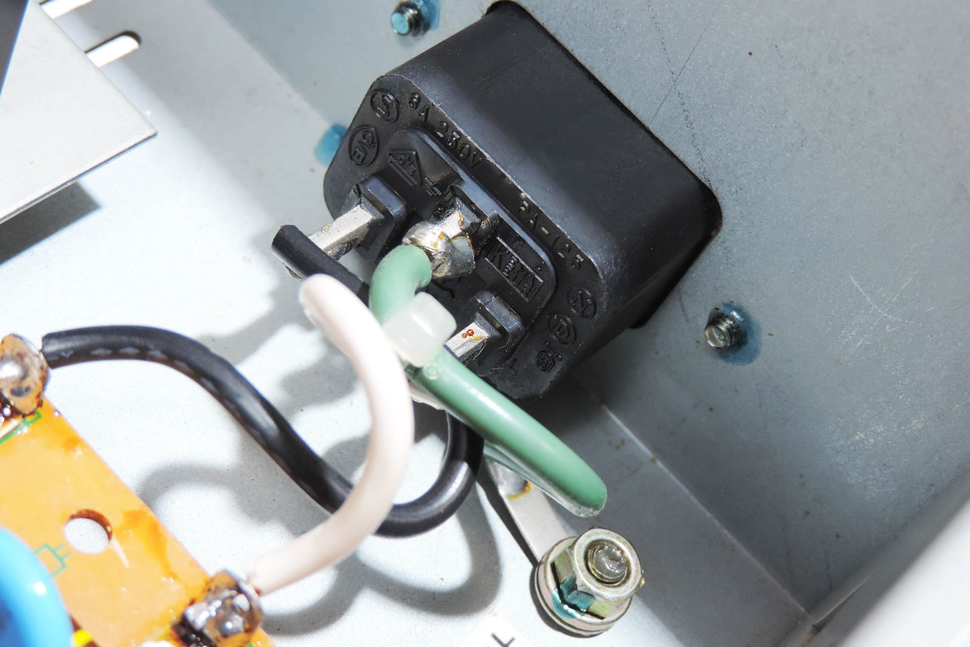
Your MKS-80 MUST BE EARTHED. If you have a 2-pin IEC C10 mains socket, you must replace it with a 3-pin IEC C14 socket. The earth pin should be connected to the MKS-80 chassis. There's a hole in the lower case in between the mains socket and the side of the MKS-80 chassis which will take a M4 screw. DO IT!!!! Aurora board B must also be connected to this point.
It is paramount that if fitted, a 2-pin IEC C10 mains socket be replaced with a 3-pin IEC C14 mains socket and that the chassis and the P0004 are connected to earth.
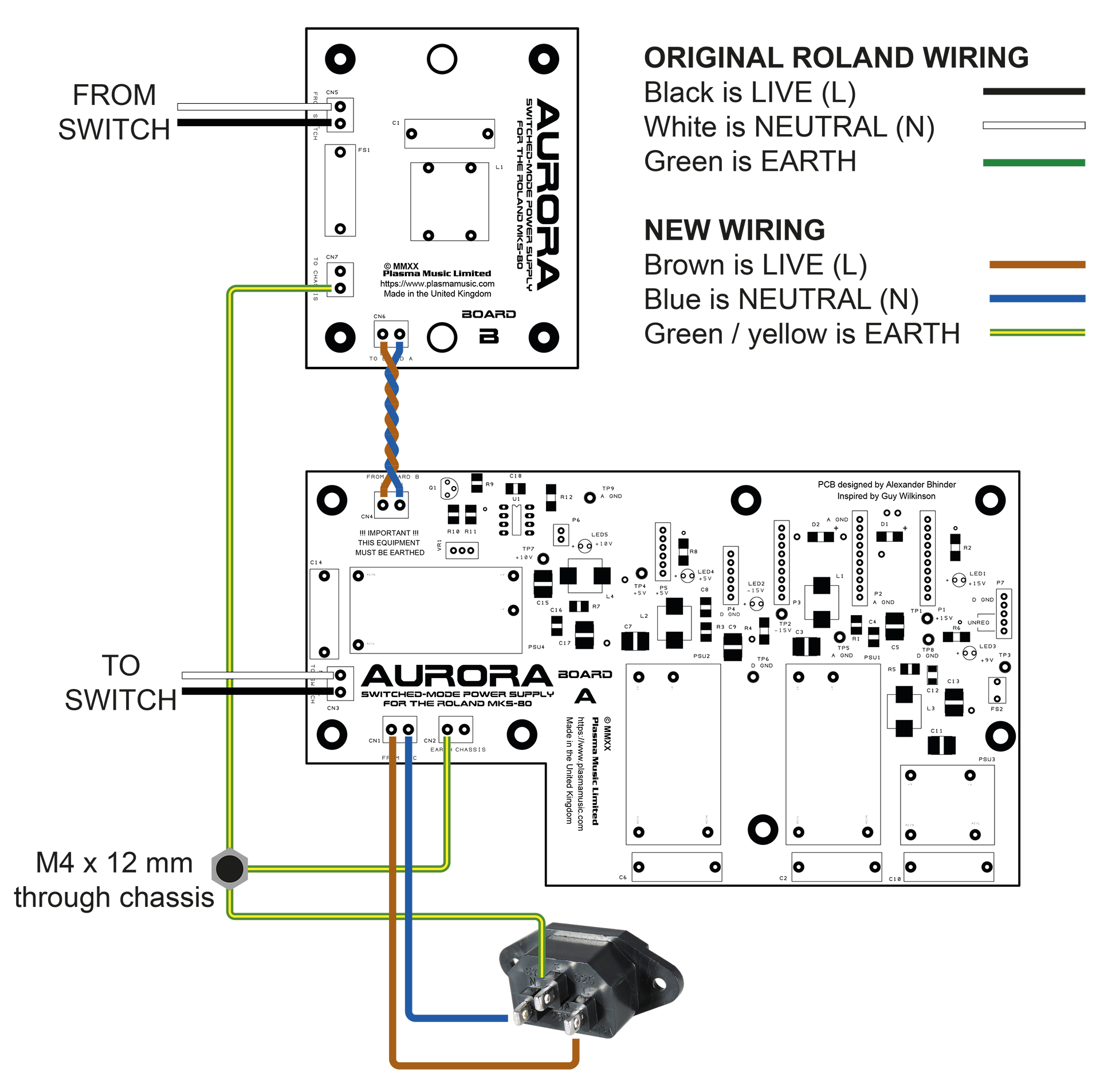
Here's a wiring diagram showing how the two Aurora boards are connected to each other, the mains input, the switch and earth / chassis. Also illustrated is the use of existing (original) wiring as well as some new wiring.
It's really quite straight-forward. You just need to take your time and remember that you're working on a vintage synth module.If your MKS-80 has a 2-pin IEC C10 mains input socket, then you MUST replace it with a 3-pin (C14) IEC socket and connect earths as shown. Also note the insulation boot over the C14 connector.The earth bonding kit for the MKS-80 includes everything you need to safely connect Aurora and your MKS-80 to the mains.
Aurora worked out perfectly. With overrated Vigortronix converters, there's a lot of headroom for the MKS-80 and on top of that, things don't get hot. The carefully designed filters on the back of each converter ensure that Aurora is dead quiet. These are important and you simply won't find them in a commercially available off-the-shelf power supply. Aurora retains a vintage feel with it's through-hole LEDs and fits perfectly into the space left after the original transformer and power supply re removed. No hum, no worries about collapsing supplies, a much lighter MKS-80 and everything's running nice 'n' cool. 😎
It's a common misconception that filters on switched-mode power supplies are there to prevent noise going into the host. The filters actually inhibit noise from the host going into the power and thus, being redistributed.
UPDATE - 7th October 2020
Since August's flood, I've had to move ops back home, temporarily. It's very cramped, things are taking longer (it took me two days to find my oscilloscope) but Julie my wife, is amazingly patient and understanding and a big support during this challenging time.
I currently have three MKS-80s in for Aurora and OLED module upgrades. Two of them have already been done but the fourth (a Rev 4 at the back), has a dead voice which I need to fix before I do anything else.
MKS-80 heaven; two Rev 5s and a Rev 4 (ex Trevor Horn), in for Aurora and OLED upgrades.
UPDATE - 2nd December 2020
So the past few months has seen more than a few Aurora sales and installations. Many customers whose units I've had in, have asked if I could also install my Live Forever memory back-up battery mod and it got me thinking.
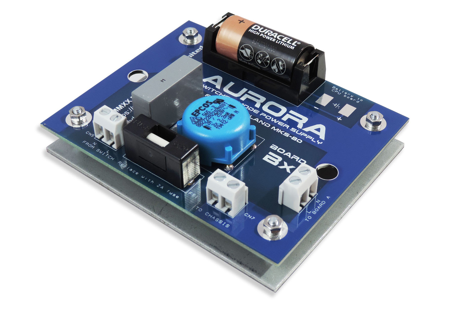
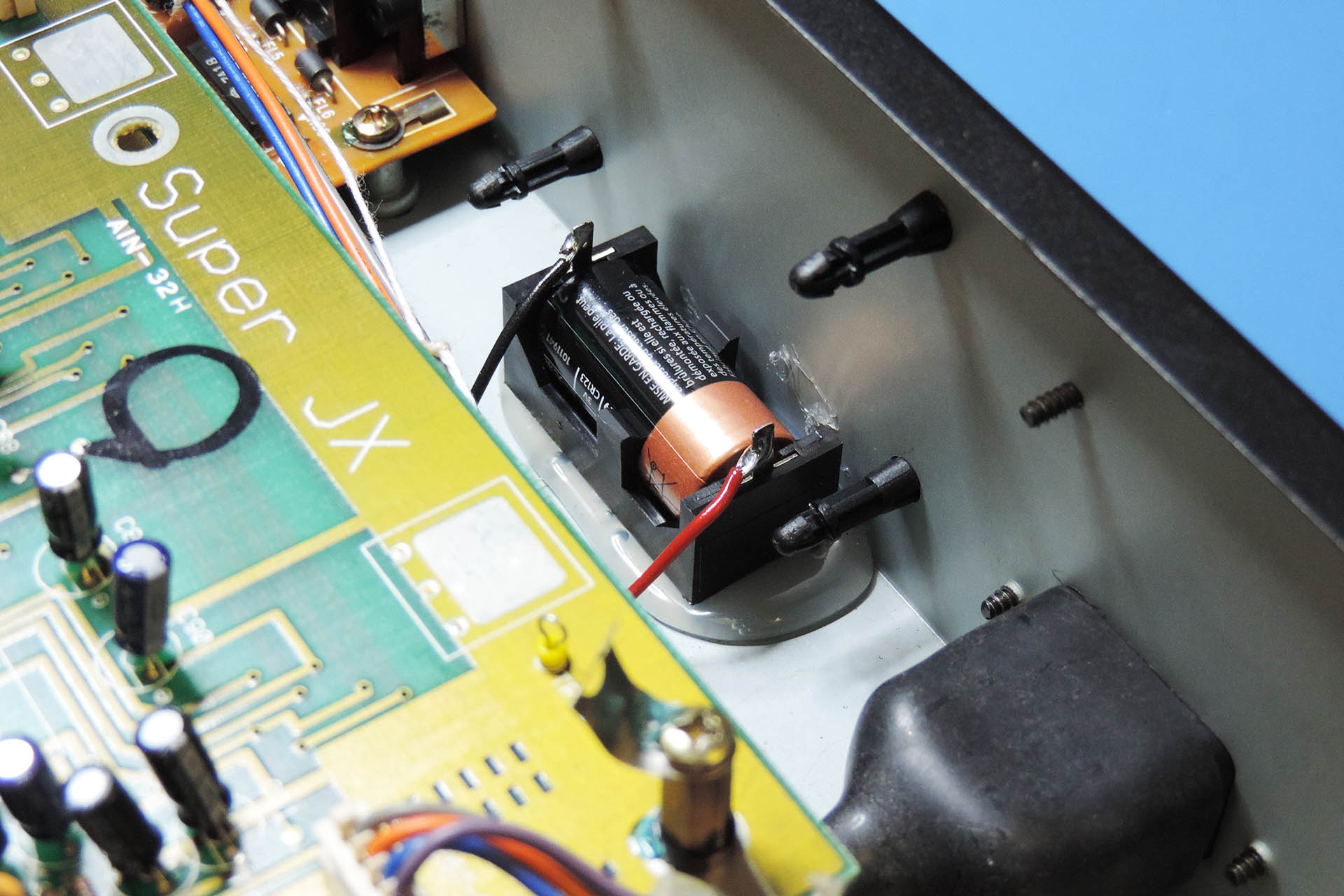
Aurora has two boards. Board B comprises mains protection and filtering so, not a lot. With a little nudging, I was able to fit a CR123a battery holder on to the PCB and so Aurora Bx Board was born! Read more about it here.
Aurora Board Bx with on-board back-up battery mod, is now available.
UPDATE - 24th December 2020
Aurora installation instructions are now available in German.
Die Installationsanleitung für Aurora ist jetzt in deutscher Sprache verfügbar.
UPDATE - 24th April 2021
Aurora is now offered with the optional V06 data cartridge re-enforcement bracket. Such a cool solution to a problem that many Roland MKS-80 owners will be familiar with, the V06 basically strengthens an undamaged cartridge slot and reinforces a broken one by putting 2mm of solid steel behind it!
V06 bracket for Roland MKS-80 broken data cartridge slot assembly.
Existing Aurora customers take note; once your Roland MKS-80 is open, V06 can be installed in a few minutes, with just a M3 (5.5mm) nut-runner.
Here are a few pictures of customers' own installations.
I'm deeply concerned about the environment and the exploitation of labour and so I always use local manufacturers in preference to the Far East, with the following in mind:
I can be confident that workers are treated fairly and earn a proper wage.
I can be confident of the standard of quality of each item that is delivered to me.
Communication is important and using local manufacturers, all correspondence is quick and understandable.
I believe in supporting the local economy.
I can be confident that the disposal of manufacturing waste is managed properly and in accordance with national and EU law.
Using local manufacturers isn’t the cheapest option but the above points are important to me. I hope that they’re important to you too.
Please don't hesitate to contact me if you have any questions regarding the Aurora Replacement Power Supply for the Roland MKS-80 or, if you want to buy Aurora or book in your MKS-80 to have it fitted, please check out my store.
I often receive questions regarding the Roland MKS-80 output phase correction mod' and without meaning to do myself out of taking your money, I do feel it necessary to ask whether or not you actually need it!
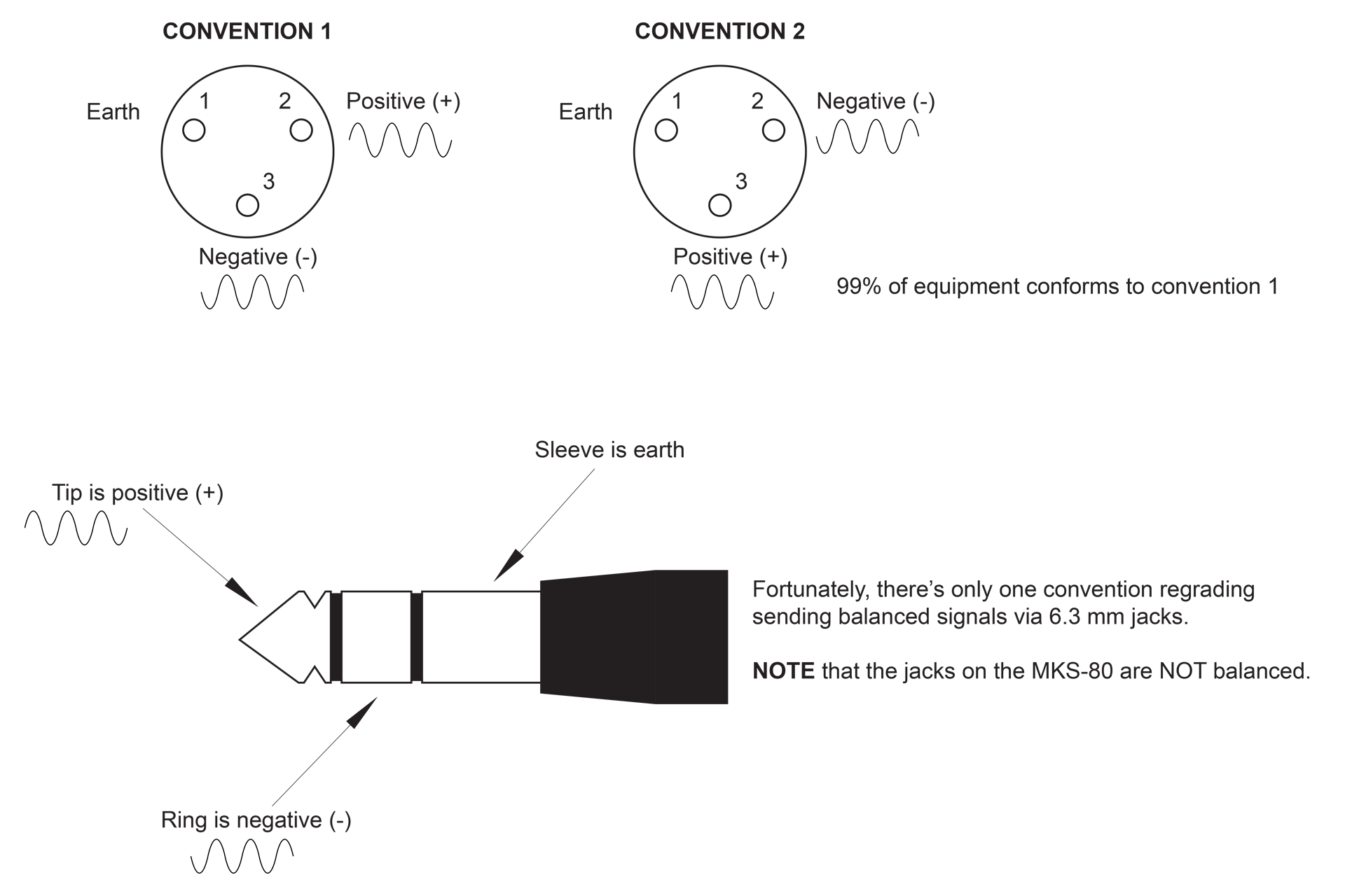
Once upon a time, there were two conventions for delivering a balanced signal via a XLR socket. Both conventions (fortunately) used PIN 1 for earth (0 V). They differed however, in as much that one used PIN 2 for the positive (+), in-phase signal and PIN 3 for the negative (-) out-of-phase signal, while the other used PIN 3 for the positive (+), in-phase signal and PIN 2 for the negative (-) out-of-phase signal.
Back in the day, it was theorised that US and European manufacturers used the first convention while Japanese manufacturers used the second. In the eighties and nineties, I designed and built a lot of recording studios, live performance systems and guitar racks (remember them) and I can tell you that it didn’t really matter who built the gear, stuff was all over the place. You just had to check.
SO WHAT DOES THIS MEAN ANYWAY?
Good question! Most of the time, you can actually ignore the convention used for sending a balanced signal to a XLR socket as it’s all ‘relative’. What I mean by that, is that if the output is from a synthesiser for example and you’re only using the balanced XLR outputs, then if the signal is ‘upside-down’, it’s not actually going to make any difference!
If however, you’re using the balanced XLR outputs from a synthesiser and the unbalanced jack outputs, then you will have a problem as the signals on the XLRs will be out of phase to the signals off the jacks, as seen by the mixer those signals are going into. If the amplitude of both sets of outputs is the same, you will in fact get absolutely nothing as the two pairs of outputs will of course cancel out each other.
You can easily get around this by either phase inverting the respective inputs on your desk or DAW for one set of outputs or by swapping pins 2 and 3 in the XLR connections at one end (only) on the cable between your gear’s XLR outputs and your desk or DAW.
In a recording environment, it’s preferable to use balanced +4dBm so your Roland MKS-80 should only be connected to your desk, using the balanced XLR outputs. If that’s the case, then there’s no need to do anything.
Where phase becomes an issue is when signal processors are daisy-chained, like in the old massive guitar racks from the eighties or… (as previously mentioned) if you’re using both XLR and jack outputs.
You may just want everything to be as standard as possible in which case, things can be done internally with a very simple procedure. So, if you do want the Roland MKS-80 output phase correction mod', then please don't hesitate to contact me.
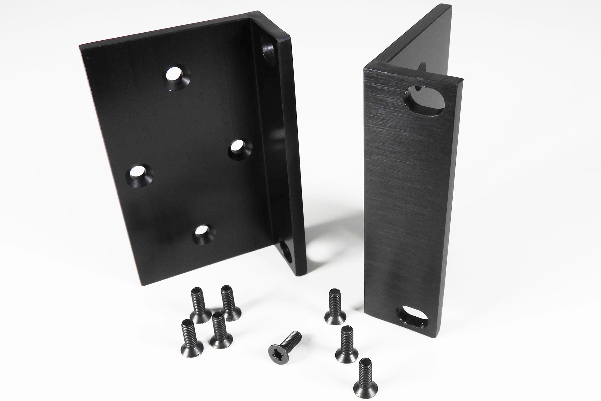
Following on from my last post 'RACK EARS FOR THE ROLAND MKS-70', I thought I'd better put this one up too, just to make it clear that I also have rack-ears for the Roland MKS-80.
As it turns out, these rack ears will also fit the following Roland 2U modules:
Roland MKS-7 Super Quartet (released 1986)
Roland MKS-10 Planet-P piano module (released 1984)
Roland MKS-20 Rack mount version of the RD-1000 digital piano (released 1986)
Roland MKS-30 Rack-mount of the JX-3P synthesiser (released 1984)
Roland MKS-100 Rack mount version of the S-10 sampler (released 1986)
Roland DDR-30 Electronic drum module (released 1985)
If you have a MKS-80 Rev 4, then you'll only use three screws each side. Yes, that's right; Roland didn't standardise the rack case 'till the Rev 5 was released!
Please note that these rack ears are only available in black and as a pair.
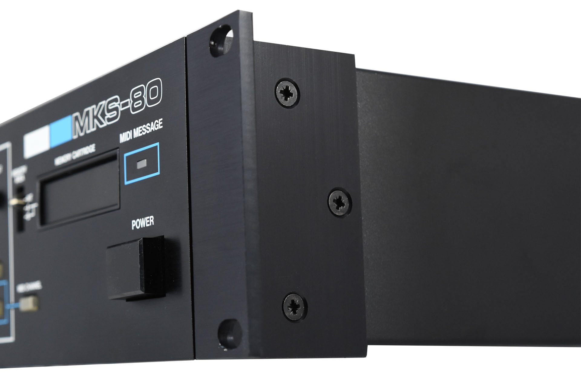
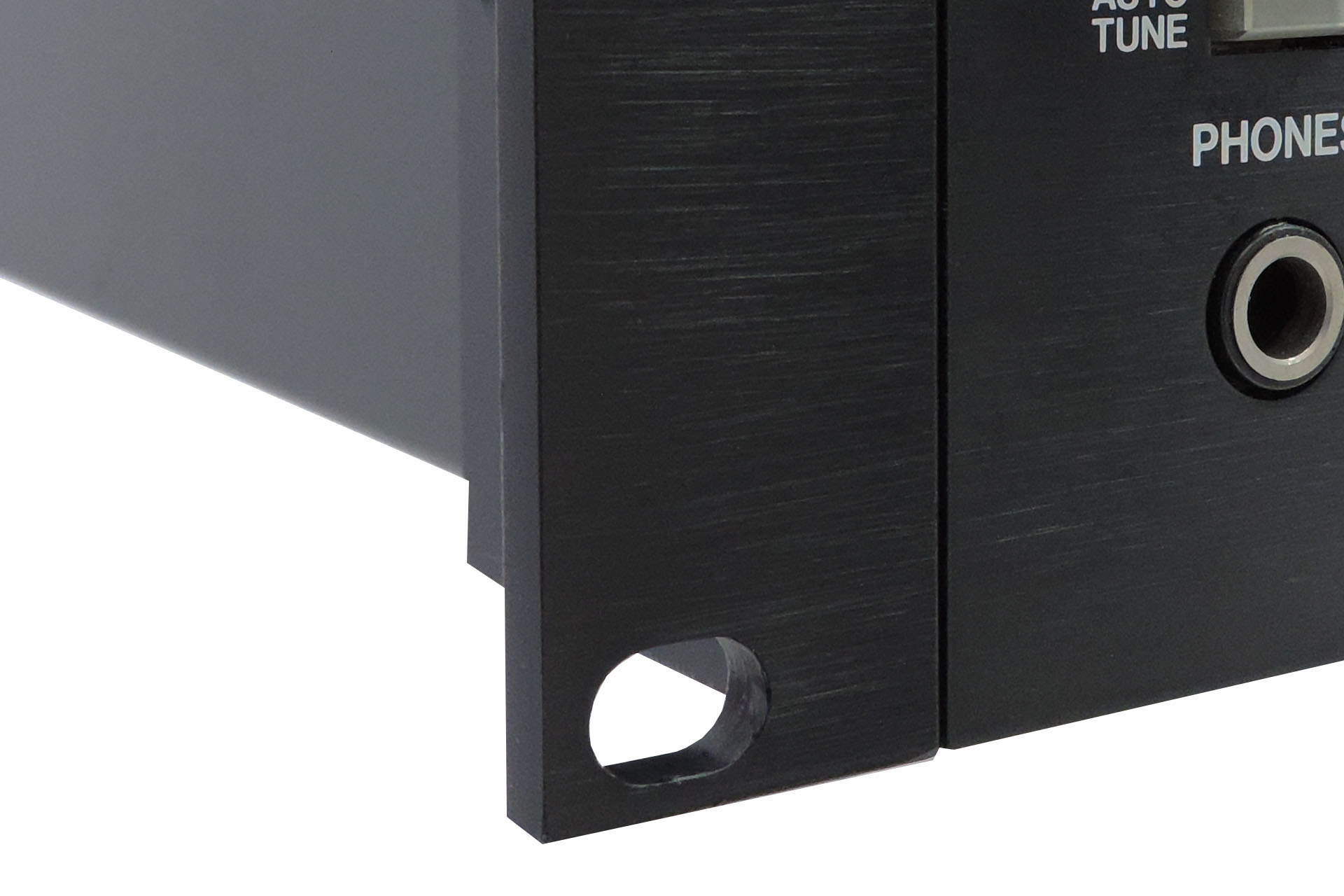
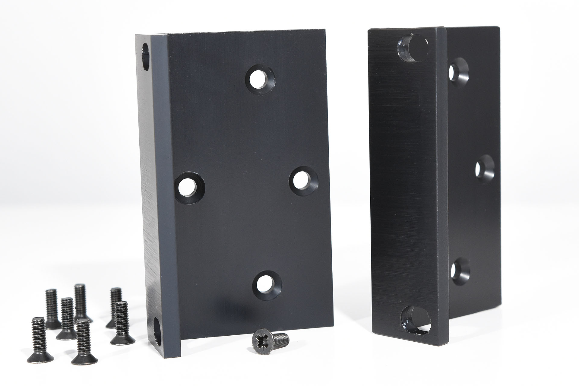
Just like the originals, these rack ears are made from aluminium with a black anodised coating and horizontally running mill finish. Apart from looking superb, they fit perfectly. Supplied with eight black countersunk M4 machine screws, all you need to fit them, is a screwdriver. 🙂
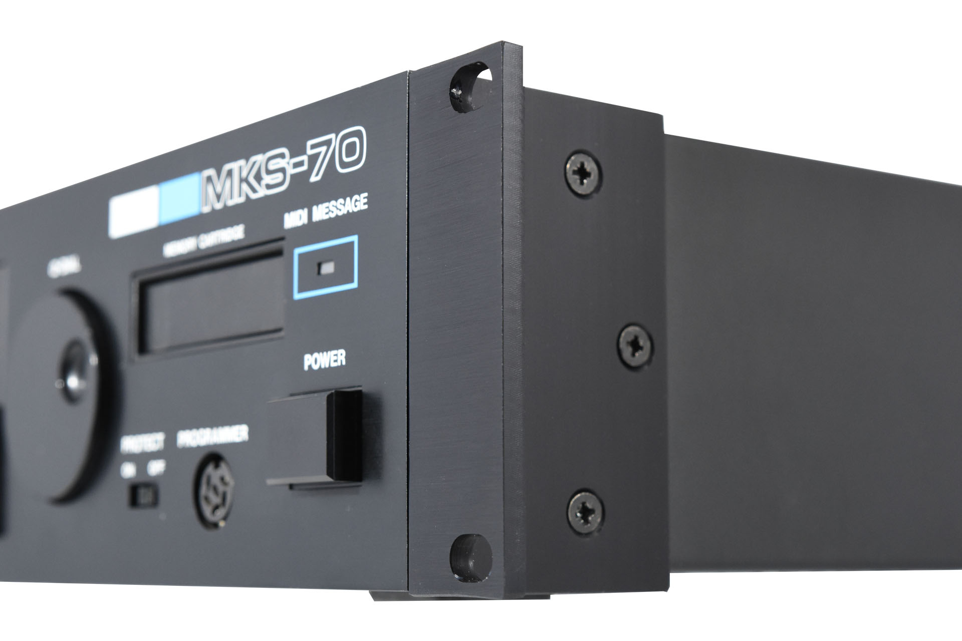
My rack-ears have a horizontally running mill-finish, just like the originals
I'm now happy to announce that these rack ear kits are available to purchase.
UPDATE - 6th May 2021
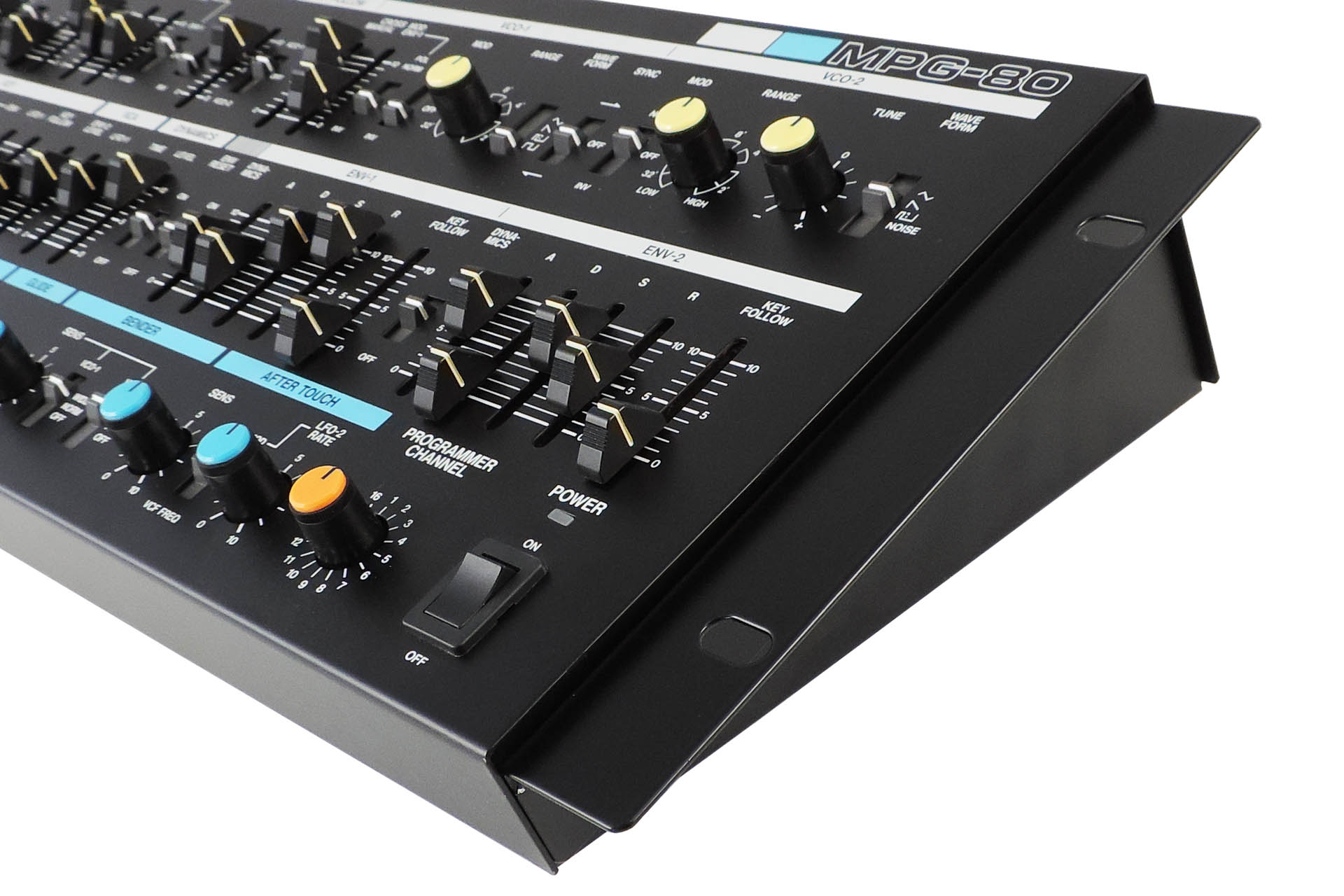
I finally got replacement rack ears for the Roland MPG-80 made up recently. Check 'em out here.
RE-MPG-80 replacement rack ears for the Roland MPG-80, mounted to my new machine!
I'm deeply concerned about the environment and the exploitation of labour and so I always use local manufacturers in preference to the Far East, with the following in mind:
I can be confident that workers are treated fairly and earn a proper wage.
I can be confident of the standard of quality of each item that is delivered to me.
Communication is important and using local manufacturers, all correspondence is quick and understandable.
I believe in supporting the local economy.
I can be confident that the disposal of manufacturing waste is managed properly and in accordance with national and EU law.
Using local manufacturers isn’t the cheapest option but the above points are important to me. I hope that they’re important to you too.
I've been meaning to do this for a very long time and finally, over lock-down, I decided to design a pair of rack ears for the Roland MKS-70.
I produced some plans from the rack ears of my own MKS-70 and this morning I got a text informing me that the prototypes were ready to collect. I didn’t bother getting these anodised as I wanted to be sure that they fit properly.
Well I have to say that I’m pretty chuffed with myself and Lenton Engineering in Watford. Always following my drawings precisely and consistently delivering perfect prototypes for me since 1985, I just love these guys.
Please note:
These rack ears do NOT fit any other Roland module
Only available in black
Only available in pairs
Just like the originals, these rack ears are made from aluminium with a black anodised coating and a horizontally running mill finish. Supplied with eight black M4 countersunk machine screws, all you need to fit them, is a screwdriver! 🙂
I'm now happy to announce that these rack ear kits are available to purchase.
IMPORTANT:Shipping price is for worldwide delivery. 🙂
I've also designed a pair of rack ears for the Roland MKS-80, which again were based on the rack ears of my own unit. These are more versatile than the MKS-70 rack ears and fit several Roland modules from the eighties. Check out this post for details.
I'm deeply concerned about the environment and the exploitation of labour and so I always use local manufacturers in preference to the Far East, with the following in mind:
I can be confident that workers are treated fairly and earn a proper wage.
I can be confident of the standard of quality of each item that is delivered to me.
Communication is important and using local manufacturers, all correspondence is quick and understandable.
I believe in supporting the local economy.
I can be confident that the disposal of manufacturing waste is managed properly and in accordance with national and EU law.
Using local manufacturers isn’t the cheapest option but the above points are important to me. I hope that they’re important to you too.
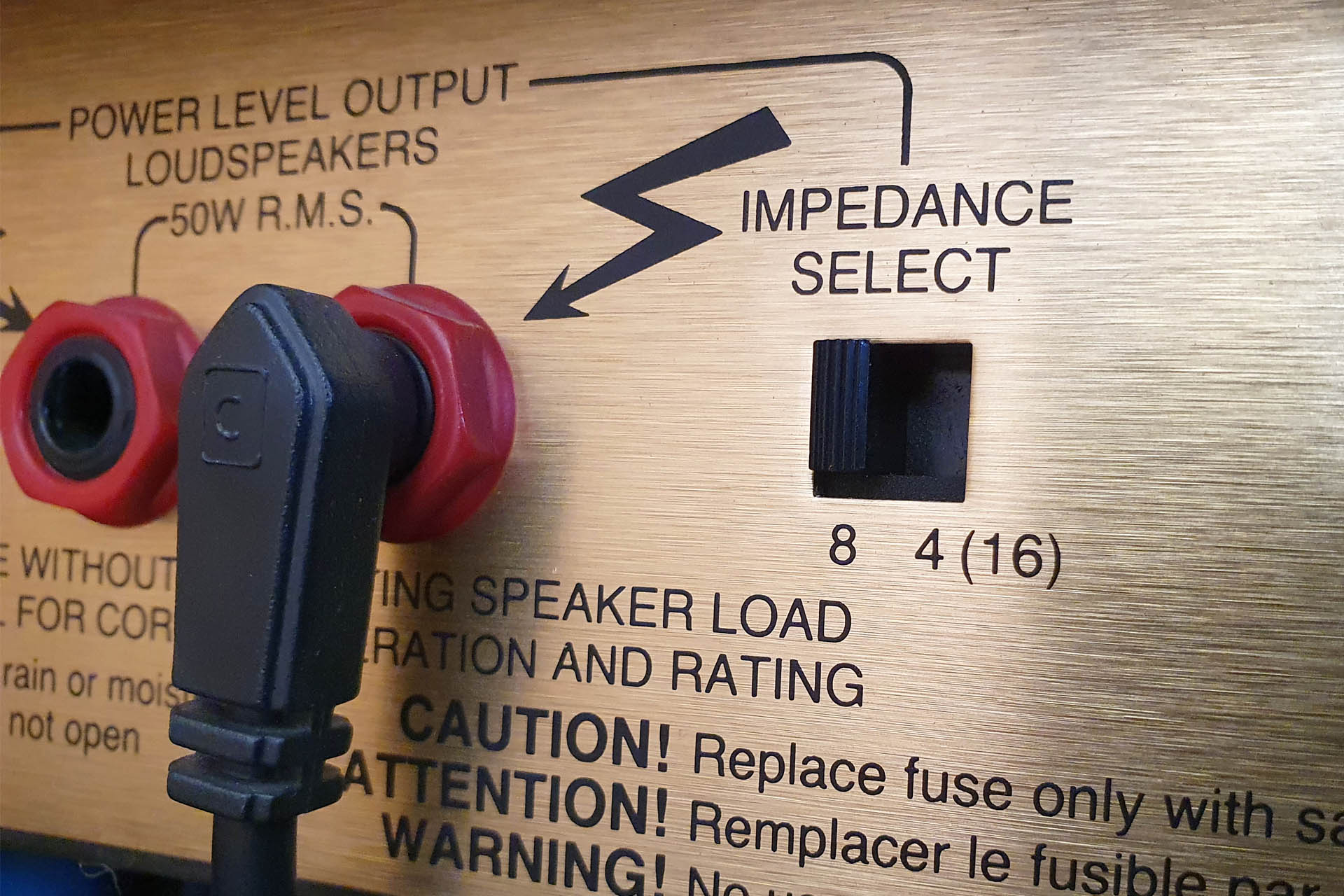
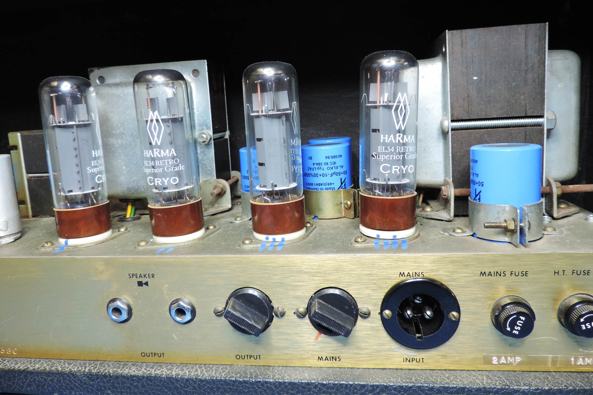
The output impedance selector on the back of a Marshall 4502 JCM900 Dual Reverb 2 x 12 combo. Default setting is 8Ω as the two on-board 16Ω speakers are wired in parallel. Read more...
Guitar cab impedance and hence, connection can sometimes be a bit of a mystery but is critically important if for example, you’re using valve amps. That’s amps which have a valve power amp. If you have an amp that has a valve pre-amp section and a semi-conductor (transistor) power amp section, then it’s not a big deal.
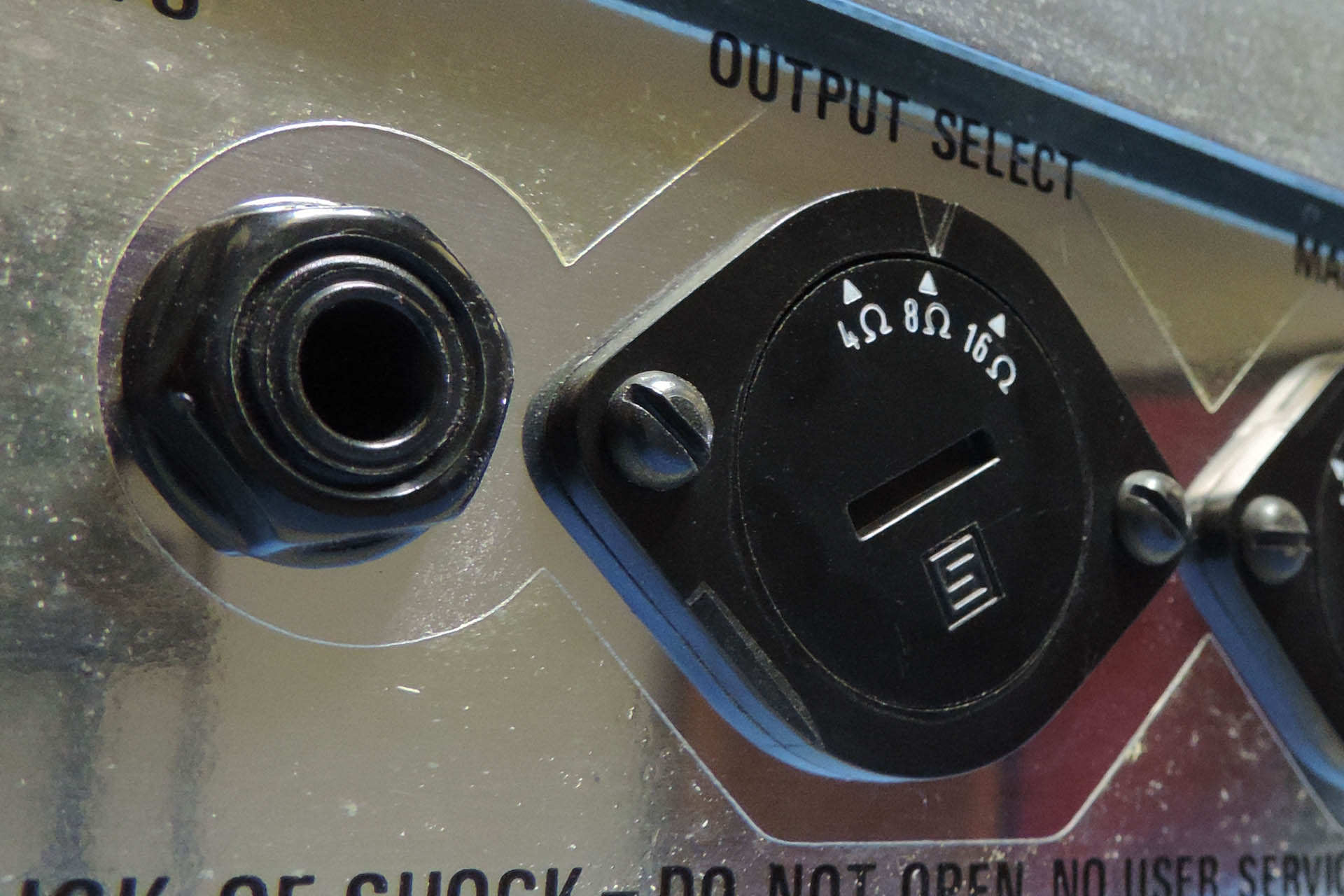
Keeping things simple; the output impedance selector on the back of a Marshall 2555 Silver Jubilee head. This amp is normally powering a pair of 16Ω 4 x 12 cabs making a total 'load' of 8Ω.
WHY IS IT SO IMPORTANT TO CORRECTLY MATCH UP CABS WITH AMPS?
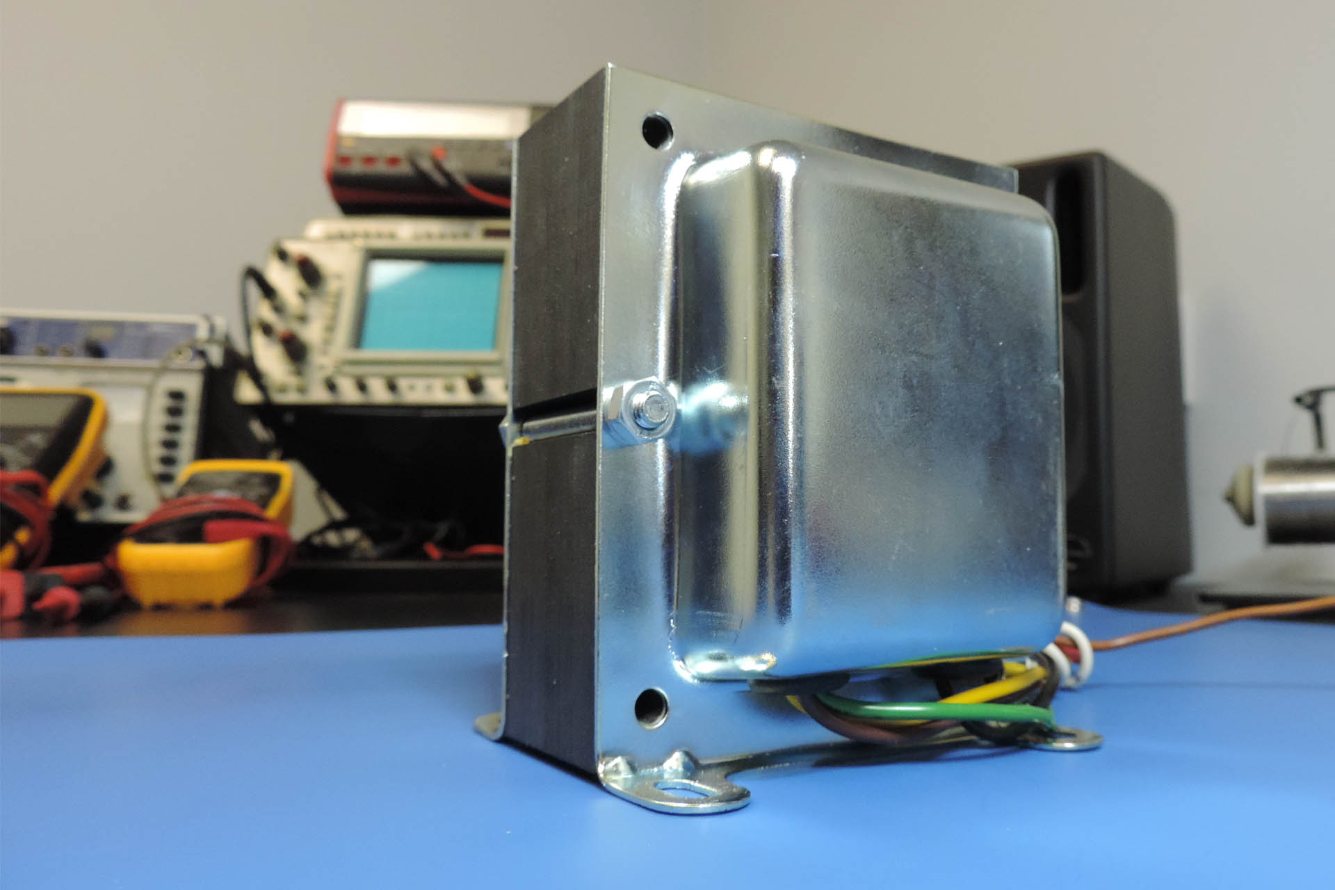
The valves in your power amp don’t connect to your cabs directly. Instead, they go via a transformer. The job of the transformer is to match up the output impedance of the valves to the input impedance of your cabs.
Impedance is like resistance. It’s even measured in Ohms (Ω). Unlike resistance however, impedance is different at different frequencies and so varies depending on the frequency at which it is measured.
To keep life simple, the impedance of a system is specified as an optimum, meaning that although the impedance changes as the frequency changes, the specified impedance is a particular quantity plus or minus so much. The impedance of for example, an 8 Ohm (or 8Ω) cab is roughly 8 Ohms across the used audio spectrum, plus or minus a bit.
BIG DEAL. SO WHAT HAPPENS IF I GET IT WRONG?
A vintage Marshall 1959 from 1972 with the back off, showing transformers. On the right is the mains transformer (near the mains socket). The transformer slightly to the left of centre, is the output transformer. The small transformer-looking thing that you can just see on the far left, used to be called a choke. It's basically an inductor used to help smooth out the mains. On a side-note, check out the old Bulgin mains socket.
If there is an impedance mismatch between a valve amp and its load (the cab that it’s connected to), the transformer in the amp is put under stress. This stress will burn out the transformer, your amp set-up stops working and you’re definitely in for a very expensive repair.
If the connection between your amp and your cab is broken and becomes what’s known as ‘open circuit’, then the same thing will happen. Effectively, your amp’s output has been set to drive a specific impedance. With nothing attached, your amp is trying to drive an infinite impedance; BANG!!!!!
This is a blown output transformer which I removed a few years ago from a Marshall 100 Watt head. The amp was immaculate and the transformer 'looks' equally immaculate. Unfortunately a dodgy speaker cable was responsible for taking out this baby.
I’VE GOT LOADS OF CABS. HOW DO I KNOW WHAT IMPEDANCE TO SET MY AMP TO?
Like anything, it’s actually quite simple if you remember a few basics. For starters, it might be worth noting the following:
Speaker cabs come in combinations of one, two or four speakers.
Virtually all individual speakers in all cabs are 16Ω.
The impedance of the cab itself, is a combination of the 16Ω speakers that are inside it. I’ll show you how to work that out in a minute.
Once you know the impedance of individual cabs, there’s a simple way to work out the impedance of all the cabs connected to your amp.
The last point is the most important; there are exceptions! While most manufacturers follow the rules and apply them to most of their amps, that’s not always the case. The Roland JC-120 is a classic example and I’ll show what I mean a little later.
So, let’s have a look at cabs. The simplest cab is the humble single speaker cabinet like a 1 x 12”, for example. With a single 16Ω speaker, the guitar cab impedance is (you guessed it) 16Ω.
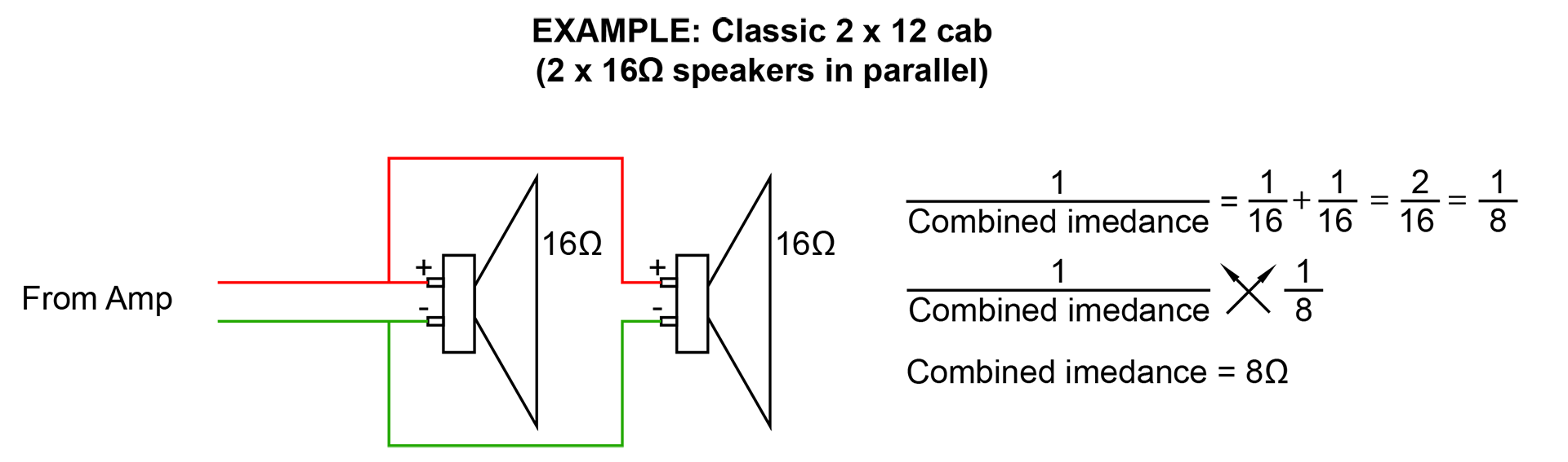
A dual speaker cab will comprise two speakers of the same impedance (usually 16Ω). These will be connected in parallel. When resistors and impedances are connected in parallel, the combined resistance or impedance is worked out as follows:
\frac{1}{Zt}=\frac{1}{Z1}+\frac{1}{Z2}
'Z' is the engineering notation for impedance, so Zt is the total cab impedance and Z1 and Z2 are the impedances of the two speakers respectively. Of course since the impedance of the individual speakers is the same, the formula becomes quite simple, like this:
\frac{1}{Zt}=\frac{2}{Z1}
So to work out Zt (the overall impedance of our 2-speaker cab):
So you might have noticed that two speakers of equal impedance, connected in parallel, have a combined impedance of half of the impedance of one speaker... you have noticed right!
If you’re still with me, let’s throw in some numbers. Let’s start by remembering that our speakers are 16Ω each:
And of course, 8Ω is the correct answer! The impedance of a 2 x 12” cab comprising two 16Ω speakers is 8Ω. That’s because they’re connected in parallel.
Two speakers wired in parallel like in a 2 x 12 cab.
The combined impedance of series connected speakers (one after the other) is much simpler; you just add ‘em up. So if for example, our two speakers in the cab above were connected in series, then the combined impedance would be 16 + 16 = 32Ω. This doesn’t actually happen, well not to my knowledge.
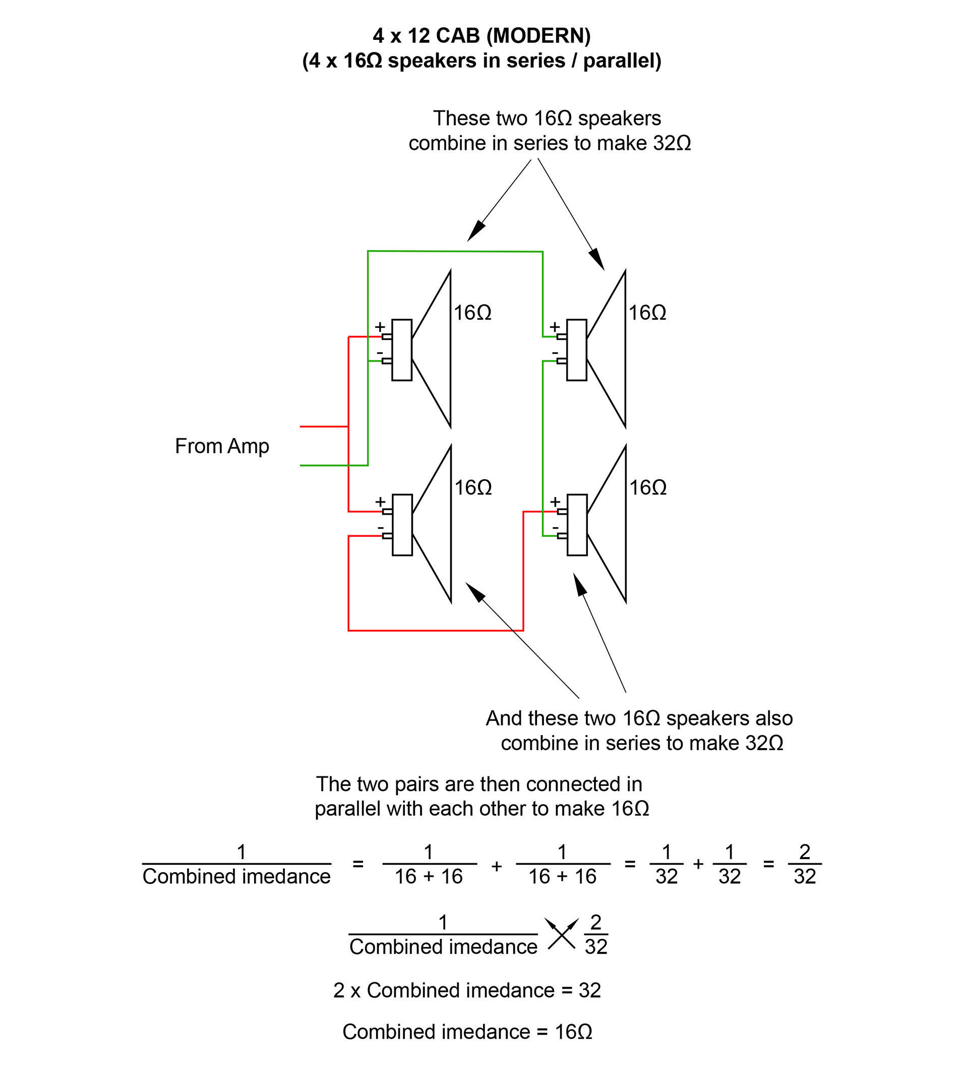
Cabs with four speakers combine series and parallel wiring to achieve a combined impedance of 16Ω. Modern cabs have two speakers in series which makes 32Ω. Another two speakers in series which makes another 32Ω. The two pairs are then connected in parallel making the whole guitar cab impedance 16Ω.
Four speakers, two pairs which are wired in series, then wired in parallel.
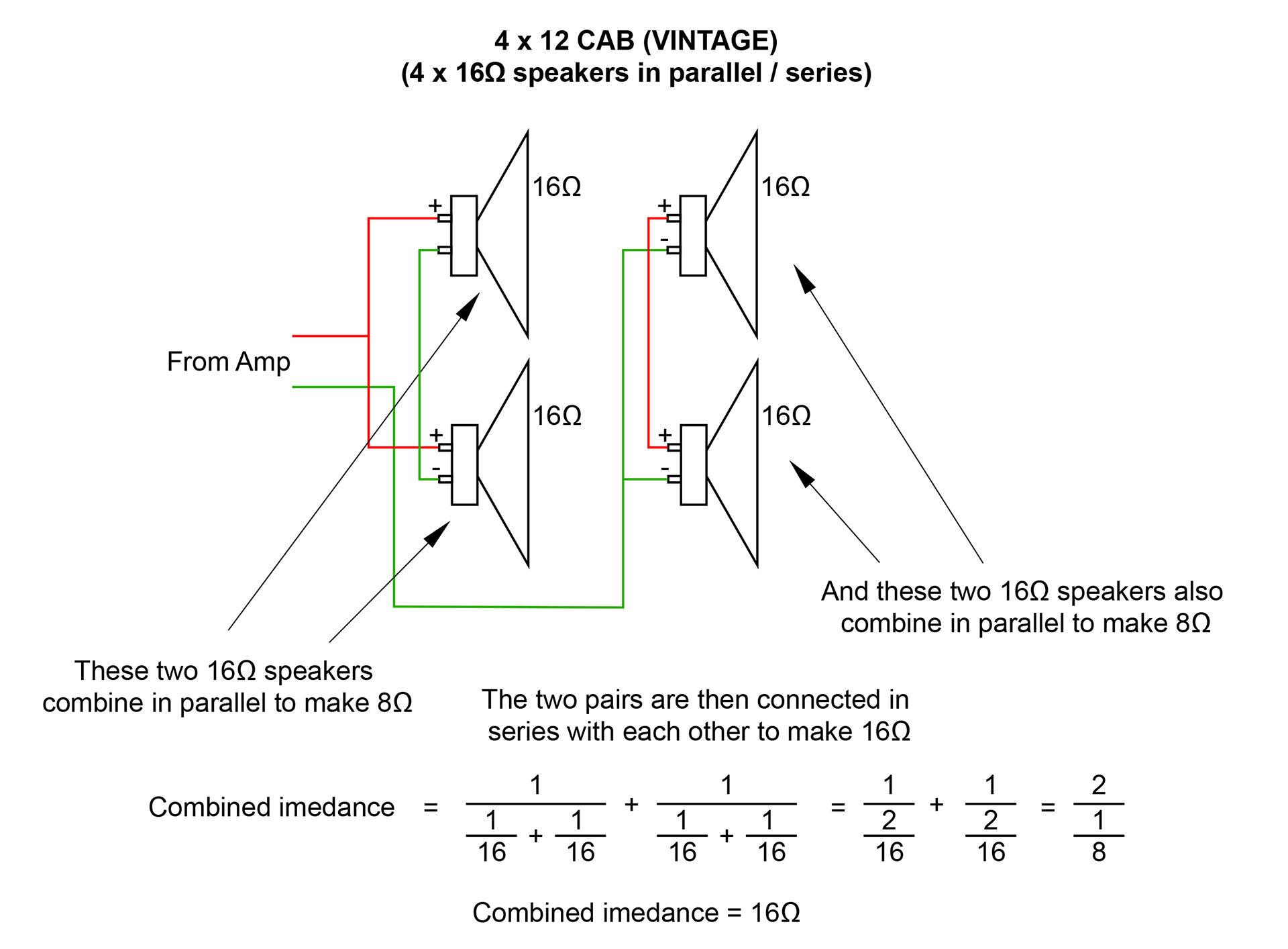
You can of course do this the other way around; parallel / series, achieving the same combined impedance. In fact most vintage cabs are wired like this so two speakers are wired in parallel to make 8Ω. The other two speakers are also wired in parallel to make another 8Ω. Then the two pairs are wired in series to make the whole guitar cab impedance (8Ω + 8Ω) 16Ω.
Four speakers wired in parallel and then series. This is how a vintage 4 x 12 will be wired.
If you're not used to all that arithmetic, it can kind of look a little intimidating. On the hand, if you go over it couple of times, it will hopefully start to make sense.
So, cabs can be treated in the same way as individual speakers although cabs are usually connected in parallel inside your amp... err... with one exception (that I know of) and that's the Roland JC-120. Firstly, although it's a combo the speakers aren't powered by one amplifier. There are two independent amps, one driving each of the speakers. Secondly and more relevant to this post, when you plug in additional speakers, they're actually connected in series with the internal speakers.
Remember that the JC-120 is a transistor amp so impedance matching isn't an issue. What it does mean however, is that the load on each amp, will increase when you plug in more speakers, thereby reducing the power output of the whole amp.
Remember that we worked out that 4 x 12 cabs are normally rated at 16Ω? Now consider using two 4 x 12 cabs to make a full stack. Plugging them both into a single amp where they are connected in parallel inside the amp, will make the overall speaker load, 8Ω, just like our very first 2 x 12 example.
2 x 12 cabs work in the same way. Each 2 x 12 cab is 8Ω. Connect two of them to a single amp and the combined overall impedance will be 4Ω so you need to set you impedance switch on the back of your amp, to 4Ω.
As with most things in life and as I've said a couple of times in this post, there are exceptions. As I say, the nice thing about standards is that there's so many to choose from! 🙂
Now then, pictured below is the back of a Marshall TSL122 100 Watt 2 x 12 combo. So is this confusing or what? For starters, the speakers in this thing are different. Marshall decided to combine a Celestion Vintage with a Celestion Hertitage. Yeah, I know people do that but I'm not a fan, to be honest. Anyway, the point is that each speaker is 8Ω. On top of that (and the second point), is that they're wired in series to create 16Ω. Well that kind of makes everything I've just said, seem like a complete and utter waste of time.
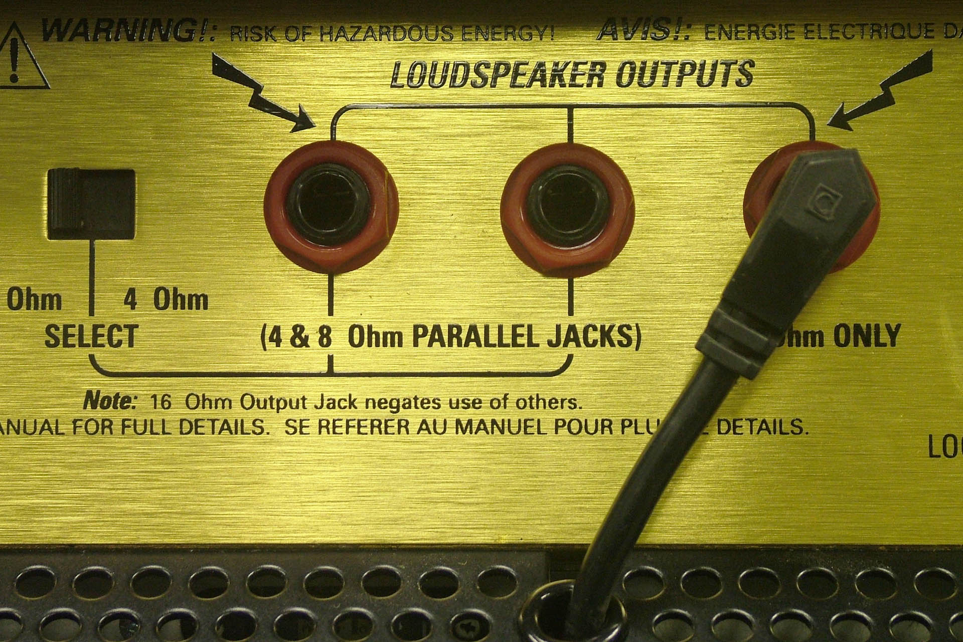
On this particular amp, the on-board speakers are plugged into the (default) 16Ω speaker output, the markings of which are obscured in the picture, by the lead. Plugging into this socket, disengages the other sockets. If you want to use external cabs, you need to unplug the lead going to the on-board speakers, plug into one or both of the other sockets and if your cab impedance is 4Ω or 8Ω, you'll then need to select your impedance appropriately. If you've got a 16Ω cab, you have to unplug the lead going to the built-in speakers and plug your cab into the 16Ω output. That's really confusing and personally, I can't see a way to use the on-board speakers and an extension cab!
I'm not a fan of the TSL series but this kind of thing really makes me back off!
Then there's the Roland JC-120 which I've mentioned a couple of times, earlier. Not a valve amp so impedance isn't at all a big deal but... it's rather interesting that anything plugged into the speaker jacks around the back, is put in series with the on-board speakers. You have to remember that this thing came out in 1979, so what was Roland thinking? On the other hand, who'd want to mess with the sound that comes out of a bog-standard Roland JC-120? It's gorgeous!
GUITAR CAB IMPEDANCE - CONCLUSION
So the bottom line is that you need to always check that your guitar amp impedance matches your cab impedance. Here's a little crib sheet that may be of some help:
SPEAKER OUTPUT 1
+
SPEAKER OUTPUT 2
=
IMPEDANCE
16Ω
+
None
=
16Ω
16Ω
+
16Ω
=
8Ω
8Ω
+
None
=
8Ω
8Ω
+
8Ω
=
4Ω
4Ω
+
None
=
4Ω
4Ω
+
4Ω
=
!!! NOT ALLOWED !!!
Make sure that you read the manual and if you do get stuck, then you can always just call me!
Oh and one more thing;
ALWAYS USE GOOD QUALITY SPEAKER CABLE!!!!!!!
Yeah, I need to emphasise that! And PLEASE do NOT use microphone cable or anything that just doesn't feel substantial. You need good quality, fat (!) speaker cable with lots of strands, if possible. The one I use a lot is Sommer Meridian 2x2.5mm2 grey speaker cable available from Studio Spares (SKU 546120).
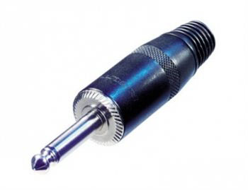
If you decide to make your own speaker cables, I strongly suggest using the Rean NYS225B jumbo 6.35mm (1/4") jack plugs.
Inspired by the great work of Guy Wilkinson from supersynthprojects.com on his P0004 switched-mode power supply upgrade for the Roland Super-JX, I decided to have a go at designing a similar Roland MKS-80 power supply upgrade. As it turned out, Guy helped a lot. After all, he's done this kind of thing before!
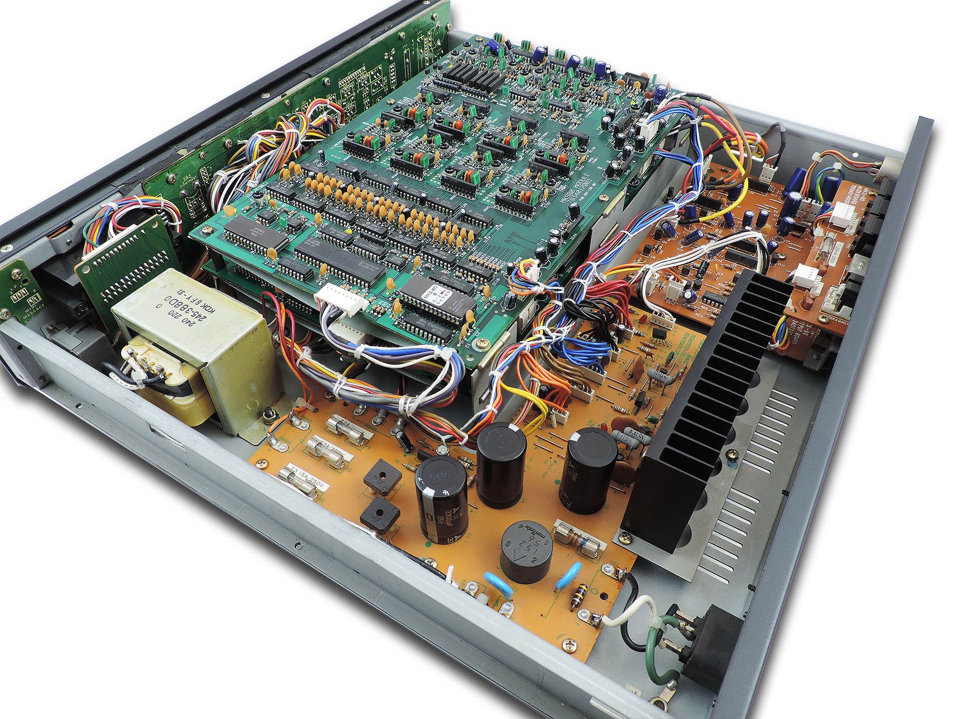
Inside the Roland MKS-80. This was truly amazing technology for the time.
So give me a little space here and allow me to explain the fundamentals of just how a conventional style 'linear' power supplies works...
Firstly, what is a power supply? A power supply is a collection of components assembled to convert a domestic high voltage AC supply to one or several low voltage DC supplies suitable for powering electronic components.
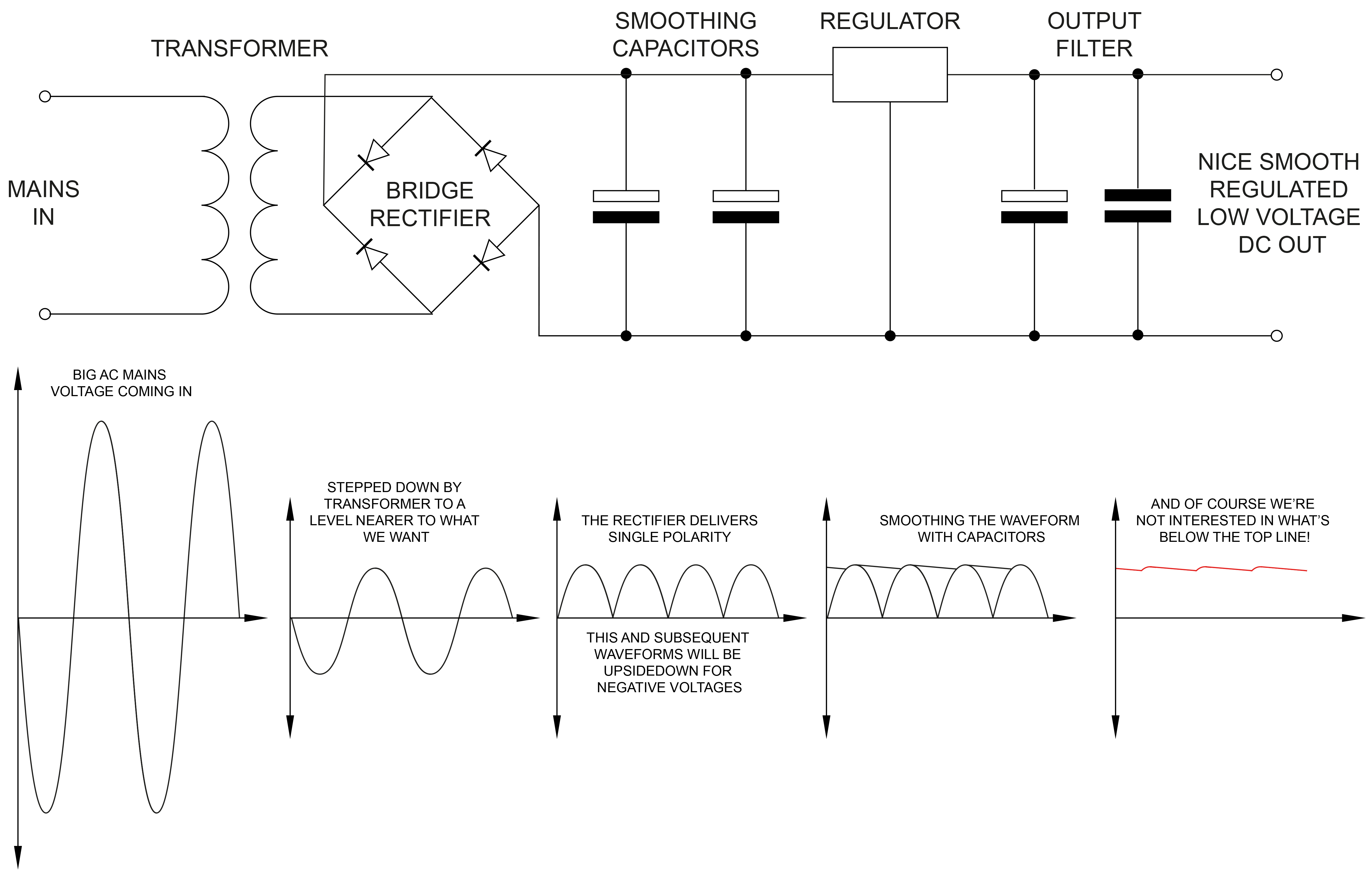
Mains voltage goes into the unit. Although always AC (alternating current in the form of a sine wave), the value of the voltage varies across the world from 240 V in the UK and Australia for example, to 220V in Europe, 115V in USA , Canada and other regions and 100 V in some other places. A transformer is used to ‘step down’ the mains voltage, to something close to what is needed to power the internal electronics. A transformer will often have a couple of 'secondary' windings which produce two or more independent low-voltage supplies.
Here's the transformer in a Roland MKS-80.
In the MKS-80, you're aiming to get a few more volts than +/-15 V for the analogue electronics and +5 V for the digital. Then you might need a little something for say, a remote programmer. In older synths, you’ll also need a reference voltage for the VCOs, for example. In the MKS-80, this is 10 V and needs to be very accurate. It was also quite common to generate other voltages, sometimes complimentary. In the MKS-70 for example, +/-5.6 V are produced on the CPU-board and in the MKS-80, each voice-board has a small circuit which produces +/-7.3 V. These voltages were derived from main supply lines such as +/-15 V from the power supply.
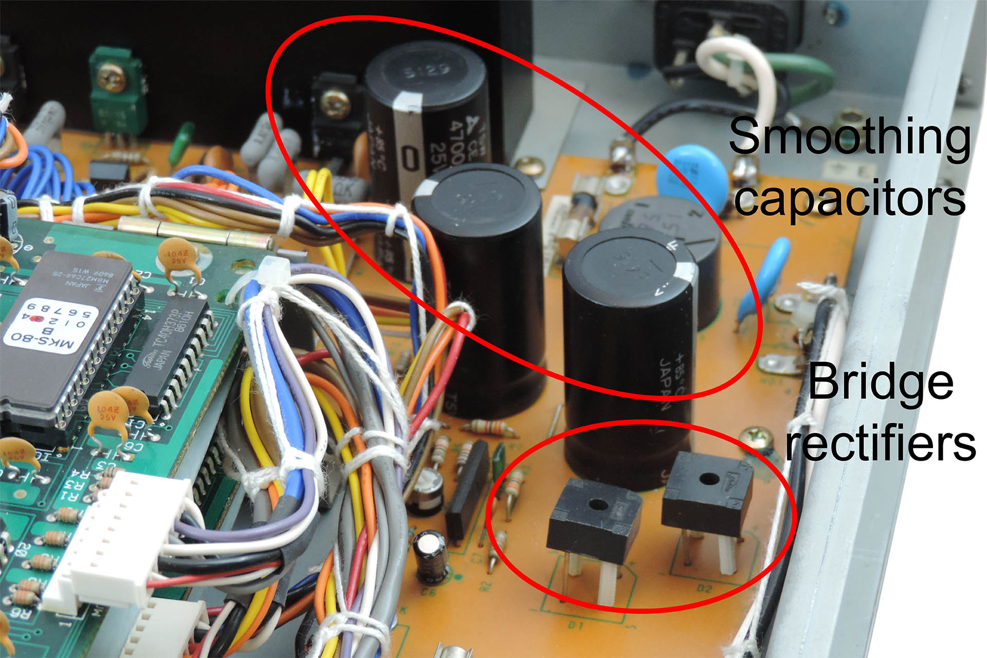
After the transformer, the voltages are still AC meaning that they’re still in a sinusoidal form swinging between positive and negative at either 50 or 60 Hertz (again, depending on where you are in the world). You need to ‘rectify’ these AC voltages which is the first stage to approximating towards DC voltages of a single polarity (plus or minus) and then you need to smooth out the result, with big capacitors.
Finally, you need to ‘regulate’ the voltages. The regulator stage performs two jobs; the first is to deliver the actual voltage required. The input voltage to the regulator will be a few volts more than what comes out from the other end. The regulator 'absorbs' the difference between the input and the output voltages and dissipates this as heat. The second job of the regulator is to maintain the required voltage as the demand for current varies.
So, you normally have one big transformer with perhaps a couple of secondary windings to bring things down. After the transformer, you'll have a couple of rectifiers and then one regulator (and associated filter circuitry) for each supply.
Linear power supply basics
It doesn't stop there. You may have noticed that some power supplies are 'larger' than others. Obtaining the desired voltages is one thing but electronics needs current. The product of DC voltage and DC current is 'power'. So more powerful power supplies are... well, bigger!
Still with me? Good!
Modern switched-mode power supplies do exactly the same job but work quite differently and probably the main physical difference is the absence of a transformer. This omission is generally a big space-saver. When however, you’re requiring several independent voltages in the same box and you basically need one AC/DC conversion stage per voltage, things can get a little crowded.
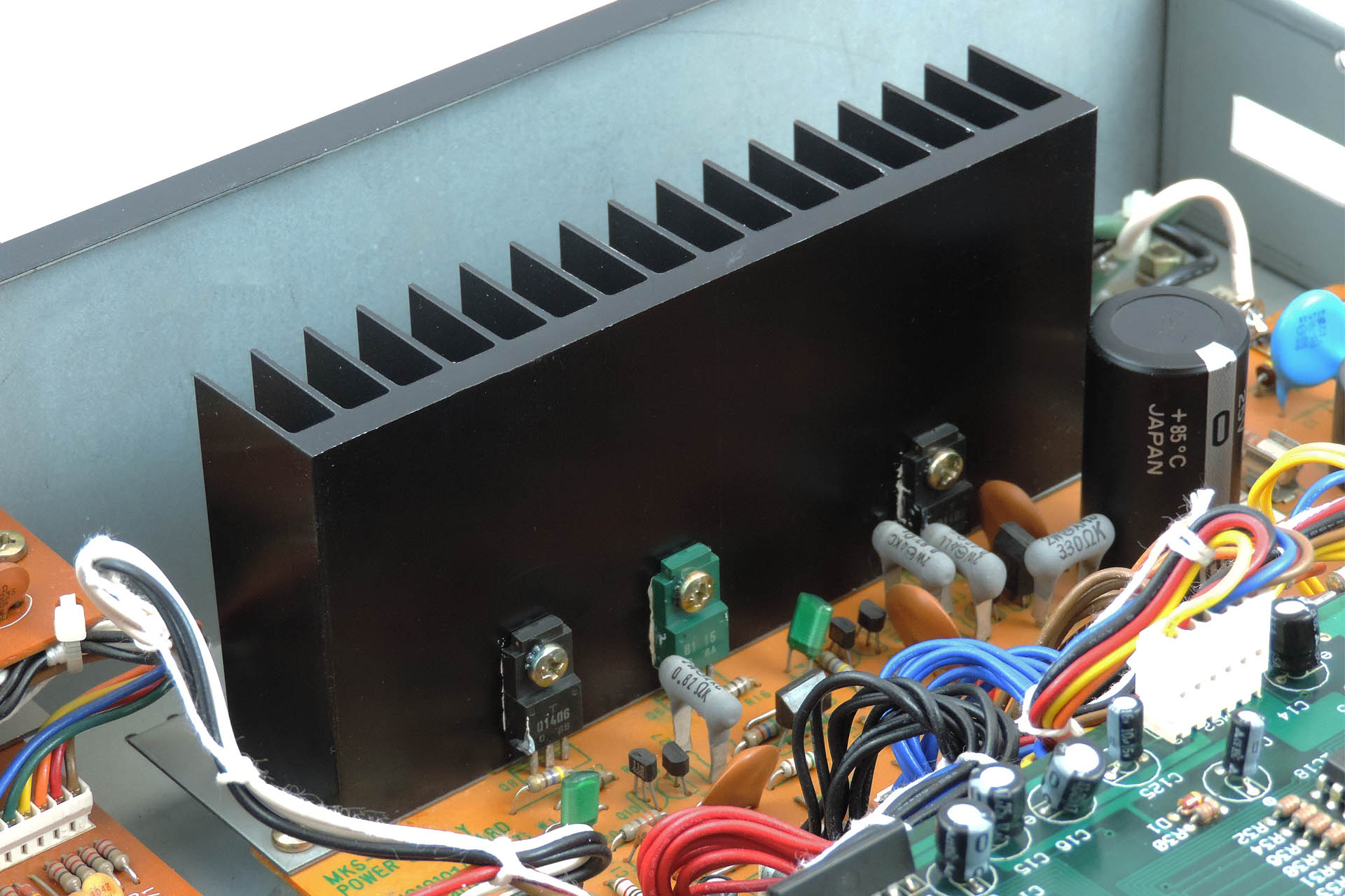
Switched-mode power supplies are considerably more efficient than their equivalent ‘linear’ cousins so generally they don’t get too hot. Some will be familiar with the sometimes, huge amount of heat-sinking present on linear power supplies and the case venting that used to go with them.
And here's the big heat-sink in a Roland MKS-80. Those little devices at the bottom are transistors that form part of the individual regulator circuits and they get particularly hot.
Due to the way they work, switched-mode power supplies can be plugged into virtually any mains supply unlike linear supplies which will require the ‘taps’ on input side of the transformer to be changed… if you’re lucky. Some older equipment would require the whole transformer to be replaced, when changing mains voltage! Oh, those were the days. Since that's virtually impossible all these years later, users of equipment that would have required a transformer change to operate in their region, can only opt for using an 'external' transformer which steps the mains voltage up or down from their region to that which the respective equipment was originally manufactured to operate in. What a drag.
So, if you have a MKS-80 that you acquired from another region and you use an external transformer, fitting an Aurora module into it, will allow you to plug your machine directly into your mains supply. 😎
So truth be known, both linear and switched-mode power supplies have their respective challenges and if not designed properly, can cause undesired side-effects, compromised performance or reduced life expectancy.
In a linear power supply, initial conversion of AC to (a type of) DC is performed by rectifiers, the output of which is 'smoothed' by large capacitors. If not chosen carefully, smoothing might be compromised thereby producing hum. Large capacitors are expensive and take up precious space and over time, the dielectric material inside them deteriorates, thereby reducing their effectiveness. Discrete or comprised linear regulators are very inefficient and can require considerable heatsinking, again increasing cost and demanding even more space. Apart from being a considerable lump of iron and wound copper, transformers generate electromagnetic fields which are seriously not wanted in audio equipment.
Switched-mode power supplies also have their issues. If designed like Aurora which comprises discrete AC / DC converters, issues such as switching noise are greatly reduced. Due to the nature of operation, there is no hum. Neither are there large capacitors that will over time, deteriorate. On the backend of Aurora’s AC / DC converters are additional filers to virtually remove further noise. And of course as has been previously mentioned, the efficiency of switched-mode supplies means that there is no requirement for huge heatsinking.
A bit of Aurora board A in early design. Careful attention has to be given to the physical layout of the filter components in a switched-mode power supply.
Since Roland launched the MKS-80 in 1984, electrical safety standards have changed considerably and it's important that anything designed today, which is to be made available to the general public, complies with modern regulations. In fact, the decision to make something like Aurora, which potentially can be fitted by 'anyone' was the hardest. On the other hand, there are disclaimers! Follow the rules and everyone should be just fine.
You just couldn't get away with this now-a-days (thank goodness).
EARTHING ISN'T JUST ABOUT SAFETY!!!!
Back in the day, a lot of Roland equipment was shipped with 2-pin IEC C10 power input sockets. Due to the way in which switched-mode power supplies work, specifically the filters, it's important that your MKS-80 is properly earthed. If your MKS-80 has a 2-pin IEC C10 power socket, then you will need to replace it with a 3-pin IEC C14 socket. This item comes as part of my earth bonding kit and can be purchased when you buy Aurora.
A CHANGING WORLD
It’s Spring 2020 and the world has been hit with COVID-19. Countries try to protect their citizens by declaring lock-downs. It’s a depressing time and hundreds of thousands die across the world while many are left alone with the stress of isolation. 2020 is turning into a time for reflection and the global community begins to realise that things might never be the same again, at least for the foreseeable future.
I was lucky, very lucky. I was at home with my lovely wife and one of my daughters who had come back from university, just before the lock-down was announced here in the UK. After a few days, I set up my laptop on the dining room table and came up with a couple of projects, simply to pass the time. One of them was 'Aurora'; a Roland MKS-80 power supply upgrade. I won't bore you with the other ideas.
A QUICK STEP BACK
Just before the lock-down, I had a couple of Roland MKS-70s come in for repair. Having one of these gorgeous synth modules myself, during the repair process, I got quite into the world of Super-JX upgrades. You can read more about that here. Having got to know Guy Wilkinson and also being the proud owner of a Roland MKS-80, one thing led to another.
The first two or three weeks were spent making physical measurements. I needed a board size! Since the massive heat sink would be redundant, I planned to take advantage of that space. Measuring, re-measuring and measuring again... many of the spaces between the mounting studs didn't seem to be exact integers, hence there was always a glimmer of doubt in the back of my head.
The design started off with the idea of using the same board dimensions as the original MKS-80 power supply. I just extended it to take up the area that was occupied by the heat-sink. As things progressed however, it was obvious that this would be an expensive approach and any consideration of commercial supply would be ridiculous. The PCB would require a panel measuring a massive 280mm x 210mm. The board is L-shaped and so, after cutting, that would mean a wastage of over 35%. The board would have been way too expensive to have been viable so annoyingly and after several design revisions, I decided to completely change my approach to using two boards; one, a regular rectangular shape, which would occupy the main area of the original board and heat sink and which is known as Board A and a second board which would accommodate the front-end high-voltage components and which would mount where the original transformer was, known as (you guessed it) Board B.
Checking board size and more importantly, mounting hole alignment, took a long time. I think the paper model pictured, is version 17! Notice that even at this stage, I wasn't confident enough to disconnect the original power supply in my own MKS-80!!!
I must confess that despite having spent the past thirty-five years servicing studio equipment and having been Roland UK's Group Service Manager in the late eighties, I was still very apprehensive about operating on my own lovely MKS-80, which I bought from Roland as a staff purchase and which is in beautiful condition.
Unlike the MKS-70, the headers that distribute power to the CPU-board, voice-boards and output-board in the MKS-80, are grouped by voltage as opposed to destination. This means that all the +15V supplies are on one header, all the -15V supplies on another and so on. Also unlike the MKS-70, the MKS-80 PSU headers are soldered at the power supply end, to the PCB. Another consideration was the classic Roland nice 'n' tidy wiring loom. Ideally I wouldn't want to mess with that so I figured on trying to preserve the relative positions of the header connectors as best as I could.
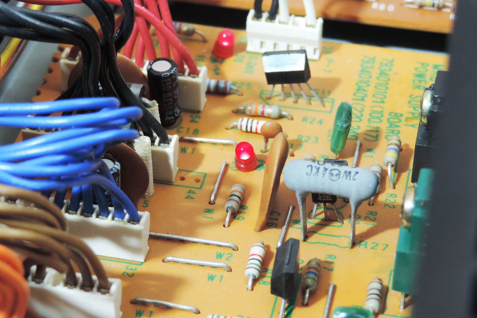
There are two other marked differences between the MKS-80 and MKS-70 power supplies; the MKS-80 has a precision 10V reference source, used for the VCOs. It also has cute little status LEDs which indicate power on the various voltage output lines!
Check out the cute LEDs but also note the soldered power (bus) headers.
Anyway, after some time, I felt as though I'd done enough measuring and so the next stage was to work out the current demand on each line. The unregulated supply wouldn't want too much as it's used to power a MPG-80 programmer / editor, when connected. According to the Roland service notes, the power consumption of the MPG-80 is 0.9W. With on-board 5V regulators, that means that the current drawn is about 180mA.
The 10 V reference source is just that, a reference and so current requirement isn't an issue. That means we're left with +/-15V for the voice boards and +5V for the CPU board.
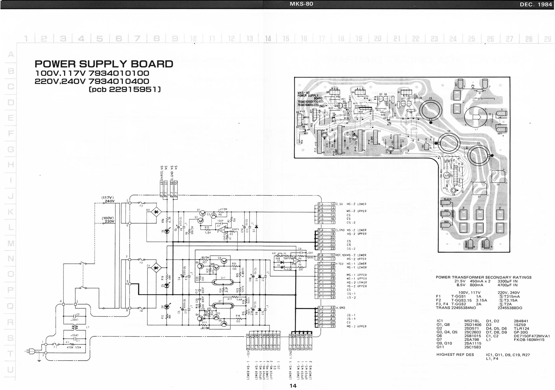
Page 14 from the Roland MKS-80 service notes (second edition, 1985) detailing the power supply.
I so didn't want to start messing around with my MKS-80, lifting components and possibly even cutting tracks, so I decided to try to work out current requirements from the schematics in the Roland service notes. I also used Guy's results from his P0004 MKS-70 power supply project, as the two machines are kind of similar.
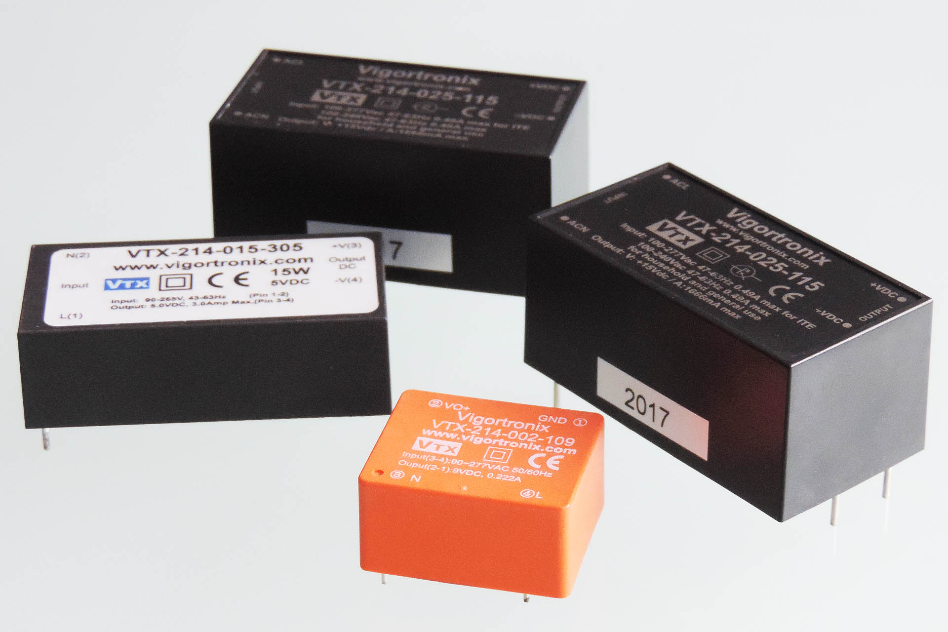
Although more expensive, I went for Vigortronix AC/DC converters. Vigortronix is just down the road from me and I've been using their transformers for many years. Technically, the specifications of the Vigortronix converters seemed much better than the Mean Wells with for example, less leakage.
After having taken my best shot at estimating current requirements, I chose 25W converters for the +/-15V rails and a 15W converter for +5V rail. The power ratings of the converters would theoretically mean that Aurora would run quite cool. For the 'unregulated' supply to the programmer port, I chose the Vigortronix 9V version of the 2W converter which will deliver 222mA.
Vigortronix AC/DC converters, much higher specification than cheaper equivalents and made in the UK.
The 9V supply is being sent outside of the MKS-80, so Roland decided to protect it with a 125mA fuse which resides on the MIDI board. I've gone a step further and dropped in a resettable fuse in line with this supply.
I decided to use through-hole T-1 3 mm LEDs instead of the surface-mount devices that Guy used on his P0004. I figured it would introduce a little retro into something that's so hi-tec in comparison to the original PSU. Back in 1984, I don't remember seeing anything other than red LEDs. This time around, I decided to give each supply, a different colour. Yeah, what the hell? And don't forget the 10 V reference source. Originally I had no intention of putting a LED on this circuit but I eventually caved in. 😎
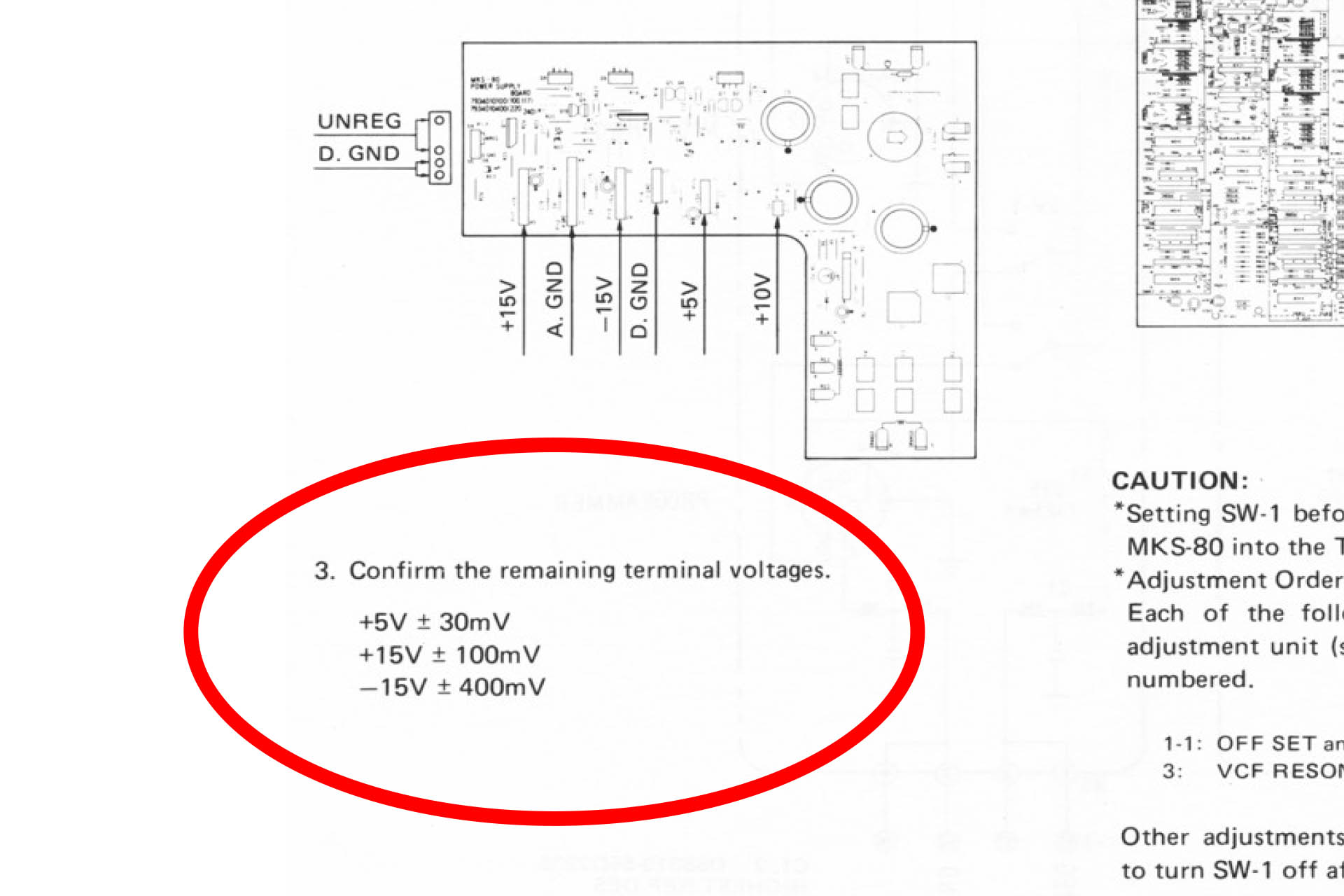
As I worked on the PCB design, I still had some concerns regarding the circuit design. Check out the tolerances of the supplies as specified on page 22 of the original Roland service notes:
Two of those figures are tight, with about 0.6% tolerance on the +5V and +15V lines. Although not impossible to achieve with the type of power supply that's being discussed here, it's not easy and such tight tolerances could be a problem. Typically, AC/DC converters have an accuracy of between 1% and 3% and of course there's a small voltage drop across each all-important filter.
Out of interest, I measured the voltages on my own MKS-80. Here's what I found:
+5V line measured in at +5.01V (10mV ∼ 0.2%.)
+15V line measured in at +15.08V (80mV ∼ 0.53%).
-15V line measured in at -15.10V (100mV ∼ 0.67%).
WOW!!!!! And that's after over thirty-five years! Roland sure could build power supplies.
Well, this realisation was kind of depressing and potentially the whole project could now be in jeopardy and might even end up being a complete and utter waste of time. 🙁
Incidentally, the Roland Jupiter 6 power supply is very similar and has exactly the same tight tolerances.
I carried on carefully studying the service notes. I looked over the schematics many, many times. I just couldn't find any reason for the high level of accuracy specified for the +5V and +15V rails and yet the accuracy for the -15V line was pretty average. The CPU-board should work fine on a little less than (bang-on) 5V. In fact slightly lower would be better. Although the critical 10V reference voltage is initially derived from the +15V rail, the fact that it's adjustable means that not even this would require such a tight tolerance on that supply.
So despite the fact that the thought of blowing up my MKS-80 if I was wrong, was constantly at the back of my mind, I decided to carry on.
The circuit for the Aurora was actually quite simple, to be honest. The PCB layout however, was not. Guy and I communicated almost every day while I was designing the PCB. In fact I only hope I wasn't too much of a pain for him! His extensive knowledge and experience of power supply filter design however, proved invaluable and we both shared a mutual attention to detail. Quite honestly, I couldn't have delivered this project without his help and so I'm actually considering the Aurora, a co-design effort. Thanks, Guy!
UPDATE - 5th SEPTEMBER 2020
Finally Aurora has landed and it's running beautifully.
Ordering prototype PCBs is a slightly nerve-wrecking experience and by the beginning of August, having made several tweaks to the PCB layout, I was waiting for the fourth and final version to be delivered. Then, on 12th August and after a major storm, my studio got seriously flooded. The experience was devastating. You can read about it here. Sod's law; the day after the flood, my final version PCBs arrived. In fact, that week was supposed to be the week that I officially launched Aurora but it all went kinda wrong due to the flood.
Once all my gear was safe and I had a plan in mind on how to move forward, I built a couple of Aurora boards and (somehow amidst all the chaos and my profound feeling of utter devastation) found the courage to drop a set into my own MKS-80 amidst the chaos and devastation of the flood aftermath. What was I thinking?!?!?
Anyway, I couldn't believe it. A bit of good luck for a change. WOW!!!! It all worked. Measuring the supply voltages, everything looked just perfect with +15.00V, -15.07V, +4.97V and +9.01V using the sample converters that Vigortronix sent me. There was no hum on the audio and it was remarkably quite, too. After an hour of being on, the converters were only slightly warm. This was great news.
Over the next few days, I put Aurora through its paces. Like many switched-mode power supplies, Aurora doesn't like being switched on and off in quick succession. That's probably not a good thing to do to your precious MKS-80, anyway. It's not a light-bulb!
Aurora worked out perfectly. With overrated Vigortronix converters, there's a lot of headroom for the MKS-80 and on top of that, things don't get hot. The carefully designed filters on the back of each converter ensure that Aurora is dead quiet. These are important and you simply won't find them in a commercially available off-the-shelf power supply. Aurora retains a vintage feel with it's through-hole LEDs and fits perfectly into the space left after the original transformer and power supply re removed. No hum, no worries about collapsing supplies, a much lighter MKS-80 and everything's running nice 'n' cool.
It's a common misconception that filters on switched-mode power supplies are there to prevent noise going into the host. The filters actually inhibit noise from the host going into the power and thus, being redistributed.
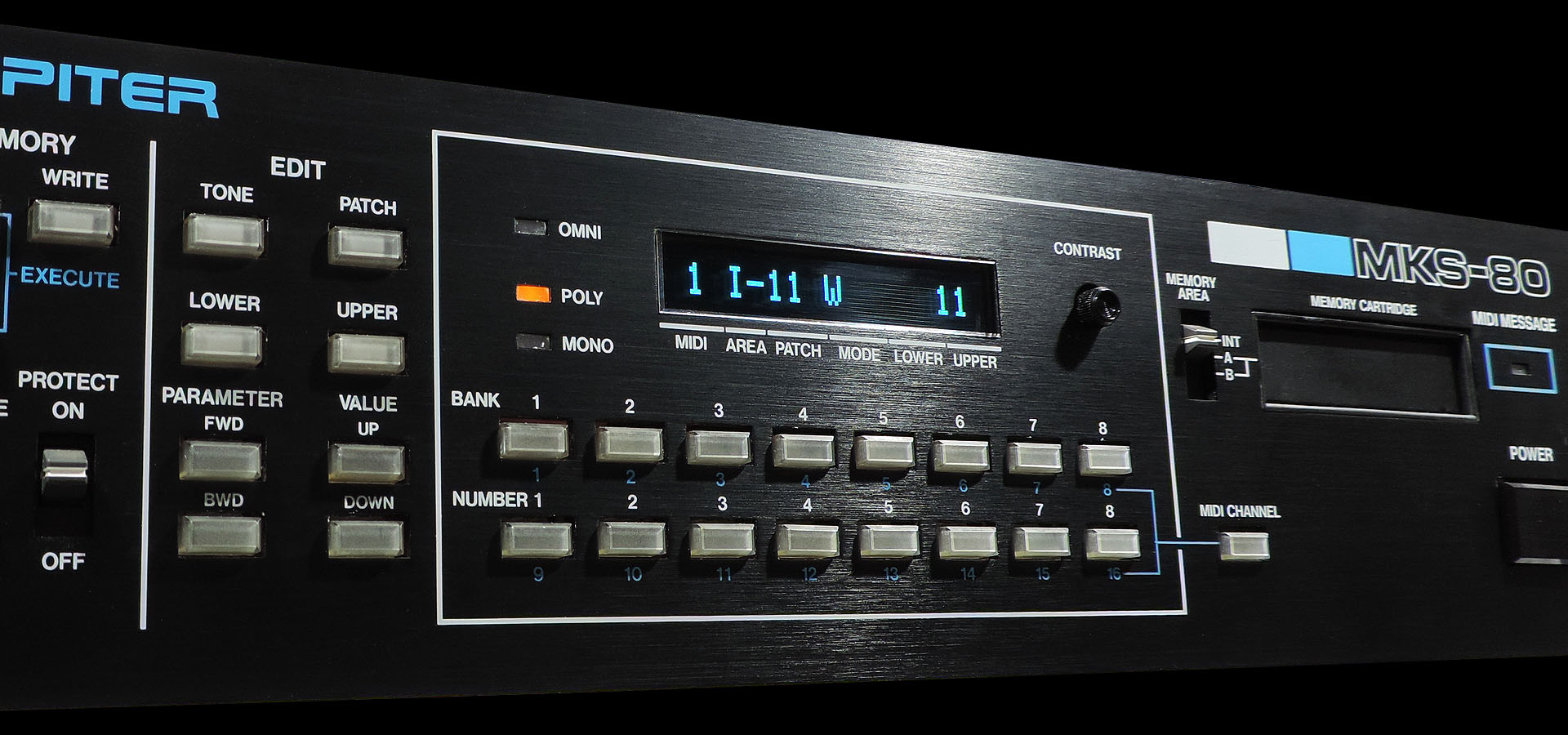
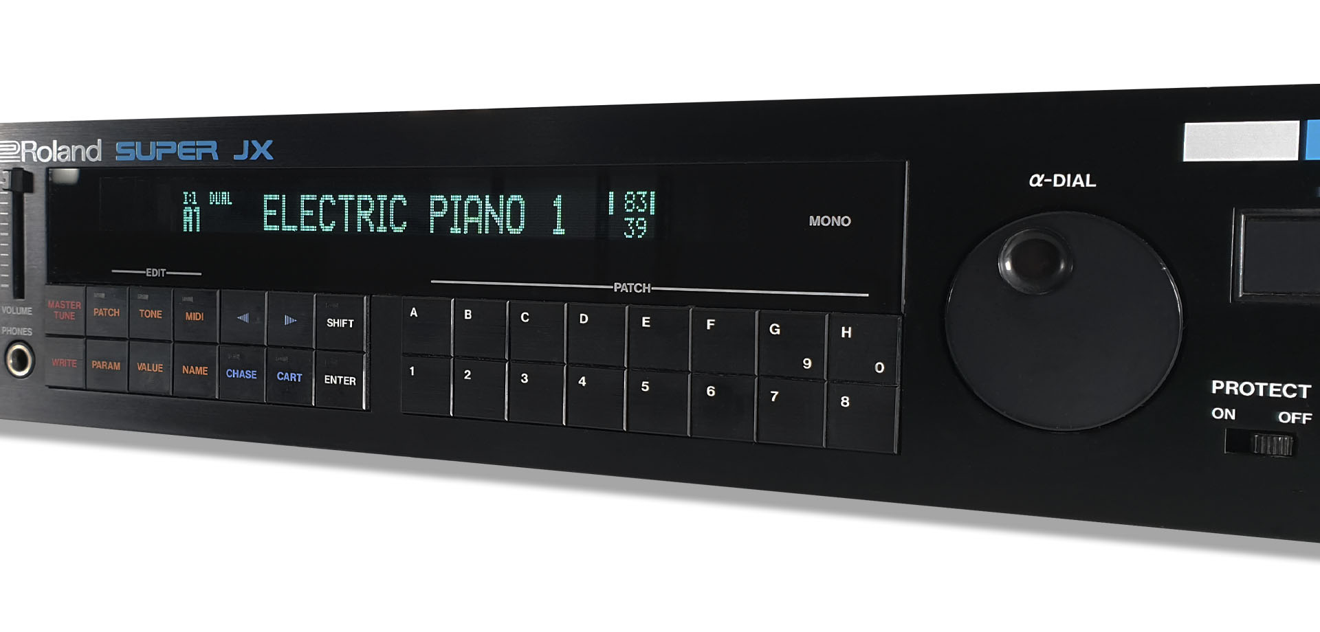
It's really difficult to convey the crisp, sharp and vibrant character of Guy Wilkinson's MKS-80 OLED modules, with a simple photograph.
Okay, so the display on the MKS-80 doesn't really tell you too much but the new OLEDs do look really cool. More importantly, you don't have to worry about the old LCD backlight packing up or the inverter starting to whine. In fact I pulled the coil and the transformer from the CPU board, as they're completely redundant, now. 😎
Anyway... designing Aurora was a challenge but thoroughly enjoyable and I learnt so much. A working modern power supply for the Roland MKS-80. Wow! 🙂 With Aurora now finally working and really well tested, please read my official post here or just buy it here:
One subject that comes up time and time again is "how to connect a USB MIDI keyboard to MIDI hardware". I've therefore decided to put up this post...
It's not exactly difficult but at the same time, you can't take it for granted that the MIDI keyboard you've got your eye on, actually has well... MIDI ports. Just about every controller seems to be designed to plug straight into your computer and hence, only has a single USB port. Manufacturers tend to offer their controllers in versions with those little 5-pin DIN sockets but they're usually upgraded versions with for example, seventy-six keys instead of the sixty-one keys that you wanted and perhaps more to the point, the version that'll fit on your desk or that's within your budget.
Oh! No MIDI port.
In a market that has been increasingly dominated by computers, some might concede that it's hardly surprising that MIDI ports are omitted from modern (MIDI) controllers. On the other hand, for those of us that have a collection of hardware sound modules, synthesisers and drum machines, MIDI controllers without MIDI ports is kinda useless!
Fortunately there's a potentially very simply and cost-effective work-around; introducing the MIDI USB host!
So a MIDI USB host is basically a small box running embedded firmware that recognises any class-compliant USB MIDI controller. That middle bit (class-compliant) is really important. A MIDI USB host is designed to be switched on and left. There's no monitor, QWERTY keyboard or mouse attached and there's no way to access the 'operating system'. It stands to reason therefore, that connecting anything to it, should be immediately recognisable and that means that anything connected to it MUST be class-compliant. Well, fortunately most USB MIDI keyboards are just that but it's always worth checking.
Several manufacturers make MIDI USB hosts but perhaps two of the most well known are those made by Kenton Electronics and MIDITech. Be expected to pay about 85 GBP for the former and 66 GBP for the latter.
For the DIYers amongst us, I've chosen to include the USB Host Controller Board V2.4 in the image above. Available from https://www.hobbytronics.co.uk/ for a modest 16.20 GBP (at the time of writing), this kit is available in a variety of 'pre-blown' versions, with appropriate firmware put on to the 24FJ64GB002 microcontroller before it's sent out. One version makes this little board into a great USB MIDI host. You'll need to connect 5-pin DIN sockets, provide power and box it up yourself but for anyone who feels a little adventurous, this can be a very cost-effective solution.
One point worth noting, is that these boxes require power and both examples mentioned above are equipped with USB power ports that are secondary to the USB port that's used to accept the connection from your USB MIDI keyboard.
MONSTER MIDI INTERFACE
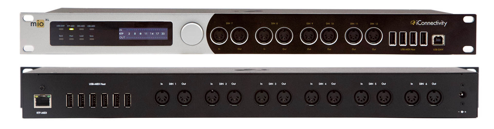
A company called iConnectivity makes a series of MIDI interfaces that are superbly designed and particularly suited for the modern audio production environment. The mio XL for example, has ten (yes TEN) USB host MIDI ports as well as a bunch of conventional 5-pin DIN ports and... it also supports RTP-MIDI via a RJ-45 connection. Fully configurable via software hosted on your computer, the mio XL also has an elegant OLED display providing an array of status information. Available for under 350 GBP, this is a seriously powerful interface that's designed to connect to just about anything that can carry MIDI.
iConnectivity mio XL - Perhaps the Mother of modern MIDI Interfaces. WOW!!!! I'd love one of these!
LATENCY
Anyone working with digital audio will be familiar with something called 'latency'. Loosely defined as the time between a signal entering a digital system and leaving the same digital system, latency is basically the time taken to digitally process a signal. If that means simple analogue to digital or digital to analogue conversion, then even that process takes a finite period. This is not the case with analogue electronics although there does exist an almost analogous parameter called 'propagation delay' but let's not confuse things just yet, eh?
When working with computers specifically, latency can be quite substantial as there's a lot going on in these boxes that we've all grown used to. Having said that, clock speeds and more efficient processing both in software as well as hardware, has reduced latency over the years and in most situations, it's not a real concern anymore. On top of that, manufacturers of audio interfaces introduced 'direct monitoring' a long time ago which was and still is a great work-around to the issue of latency.
So going back to our USB MIDI host, it should be noted that by design, the smaller boxes are very simple and are designed to do one thing and one thing only. Hence, while latency technically still exists, simply by the nature of the beast, it is negligible. I use a Kenton Electronics MIDI USB host myself and I can assure you that if latency was an issue, I simply wouldn't bother.
Following on from my post covering the installation of a replacement power supply into a Roland MKS-70, I decided to do another post on a whole bunch of cool Roland Super-JX Upgrades which I discovered during lock-down 2020. Apologies if some stuff is kinda repeated.
Back in April 2020, I got a Roland MKS-70 in for repair. It was powering up but wasn’t booting. While replacing original components that were over thirty years old on the power supply, another MKS-70 came in with err… power issues.
This all happened during lock-down so progress on the repairs was kinda slow. I did however, have lots of time to see what I could find on-line.
I very quickly came across supersynthprojects.com and over a period of days, got to know Guy Wilkinson, a vintage synth enthusiast with a very relevant background. Guy has developed a switched-mode power supply for the JX-10 and MKS-70.
A P0004 switched-mode replacement power supply installed in a Roland MKS-70. Look... no transformer!
There are two MASSIVE hidden bonuses when using something like Guy's P0004 power supply;
Unlike the original Roland PSU, the +5V supply on the P0004, is NOT derived from the +15V line and is fully independent. Hence, any fault on the +15V line, won’t affect the +5V supply.
In the event of a failure, the respective supply will simply stop working and chuck out 0V.
Big deal, so... Well, sadly, I occasionally see a MKS-70 which has had a failure of the +5V supply. If the failure is as a result of the +15V going wacky, this often results in the +15V line jumping to like +22V, thus maxing out the +5V regulator circuitry and taking out your assigner board. That’s basically a bricked MKS-70! 🙁
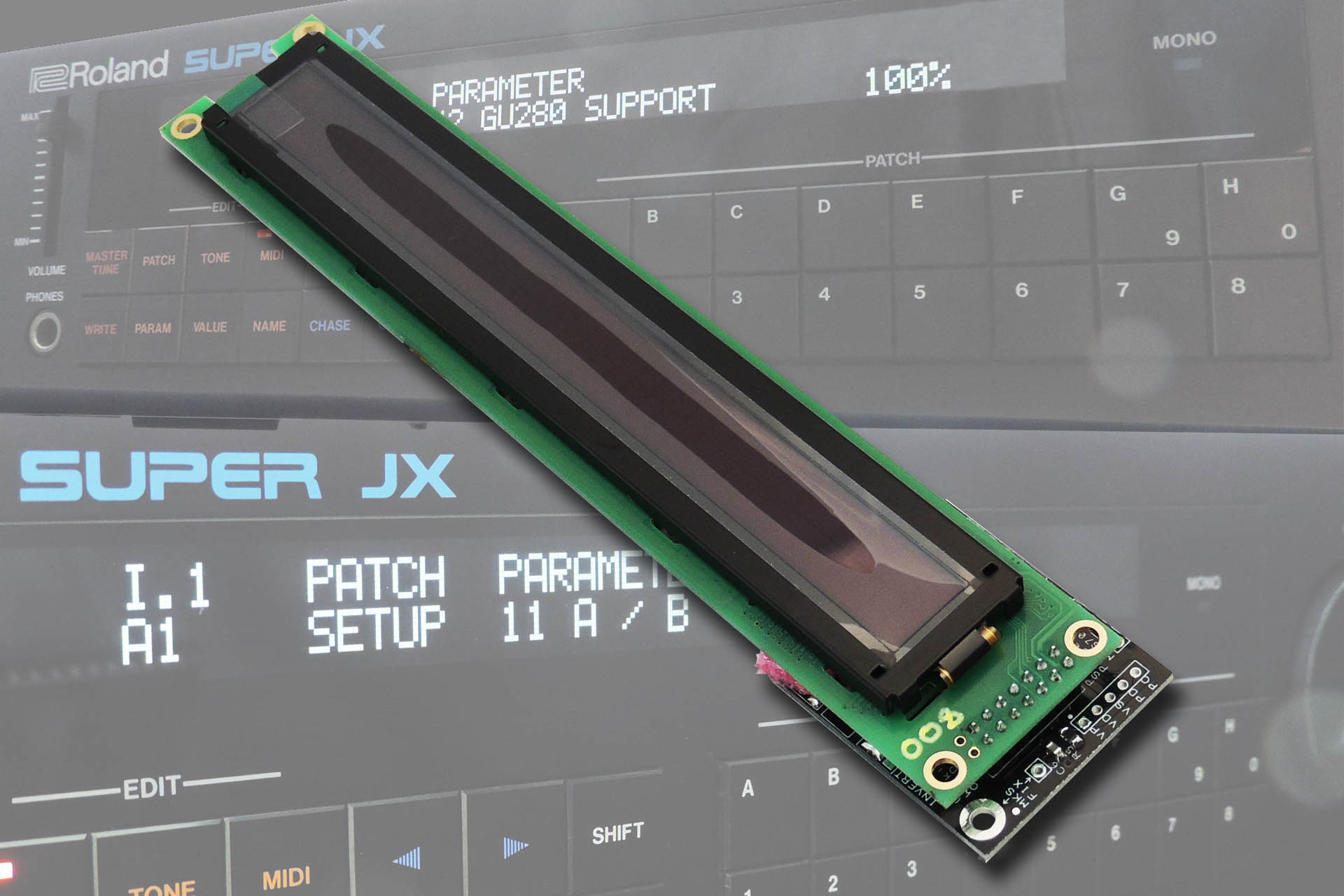
Guy also supplies a variety of displays, one of which particularly caught my attention, the Super-JX OLED upgrade display. As many Super-JX owners will know, the original vacuum fluorescent display (or VFD) as well as the FIP coil that drives it, is just about impossible to get hold of now. VFDs and FIP coils fail, so any potential replacement is well worth checking out, especially if it's going to be OLED cool.
Guy Wilkinson's Super-JX OLED module.
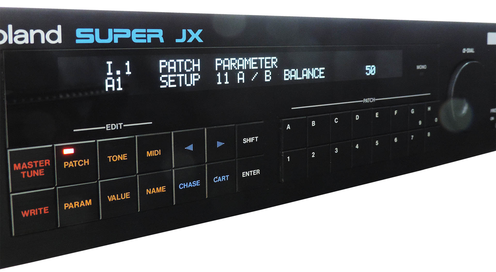
I've always wondered why some people use the adjective "sexy" to describe tech'. Guy's Super-JX OLED looks stunning and now I know. I just can't stop looking at it! 😛
Guy Wilkinson's OLED for the Roland Super-JX, installed in a MKS-70.
Guy Wilkinson's VFD module looks more like the original Roland display. With Fred's firmware, brightness of the GU-280 can be changed.
And Guy's GU-280 VFD for the Roland Super-JX, also installed in a MKS-70.
As I continued my research into the world of Roland Super-JX upgrades, I came across vecoven.com and the Vecoven PWM upgrade; a kit which provides the Super-JX sounds with pulse-width modulation. WHAT!?!?!?!
Fred Vecoven sells the PWM upgrade as a self-assembly kit comprising two small PCBs (one for each voice board), lose components, three EPROMs and two replacement 80C320 processors (again one for each voice board). An option to buy populated PCBs is also available.
Neither the self-assembly kit or the pre-assembled PCBs kit are however, supplied with cabling or connectors, presumably because there are several potential mounting options. Guy's website has detailed installation instructions for Fred's PWM kit, both for the JX-10 and MKS-70.
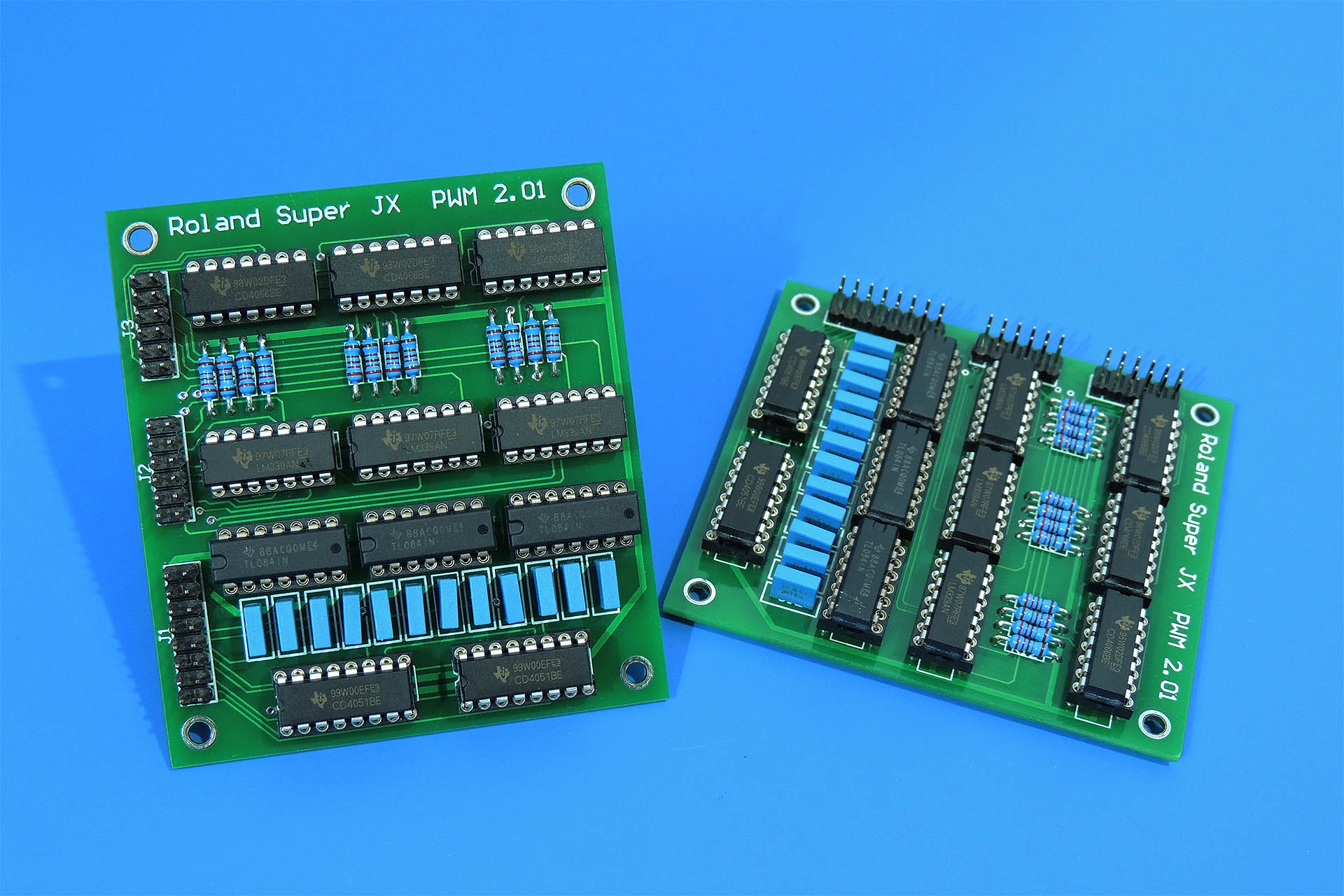
Below is a pair of Vecoven PWM upgrade PCBs which I have made up myself.
Assembled PCBs of the Vecoven PWM upgrade for Roland JX-10 and MKS-70.
The keen and eagle-eyed will have noticed that the ICs aren't soldered directly to the PCB and that instead, I've chosen to use turned-pin sockets; always a good idea!
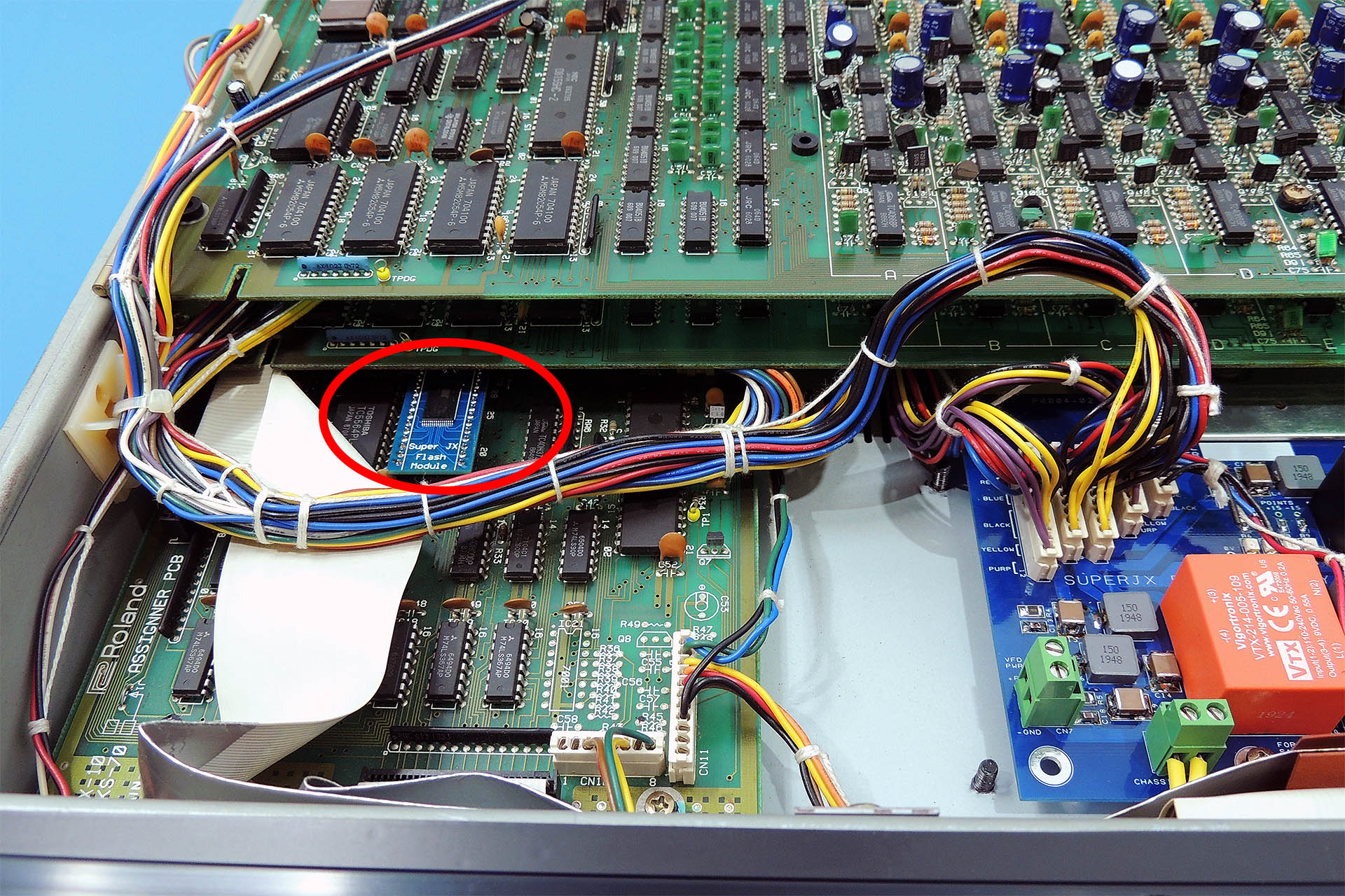
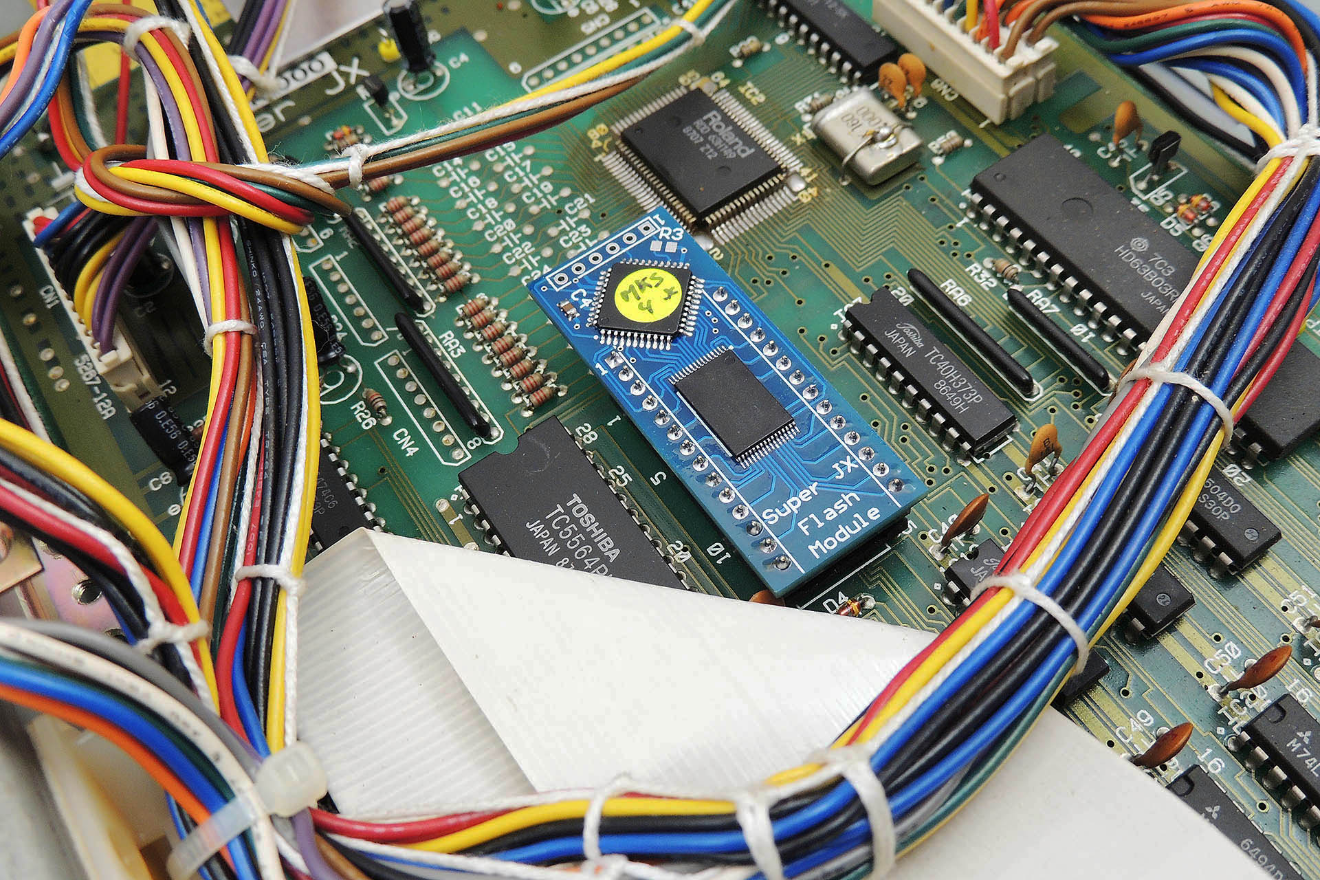
Fred Vecoven has also rewritten the Super-JX firmware and has developed a flash upgrade module which, apart from increasing the memory to the equivalent of thirty-two Roland M64C cartridges (yes, that's right... 32 x M64Cs), allows firmware updates via MIDI. Fred's firmware also gives you some control over how Guy's displays work. Hey, is that teamwork or what?
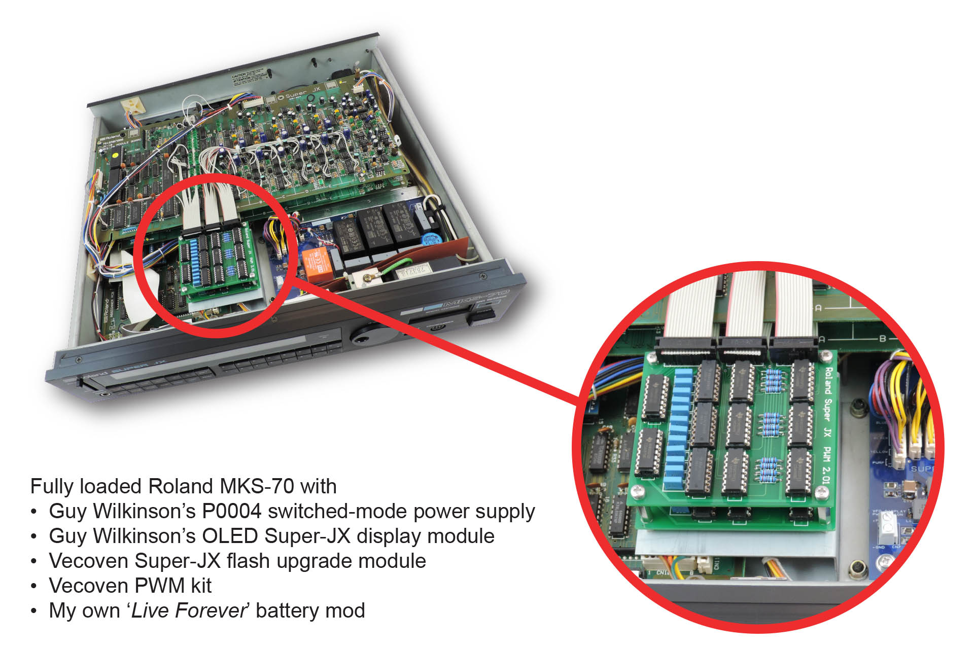
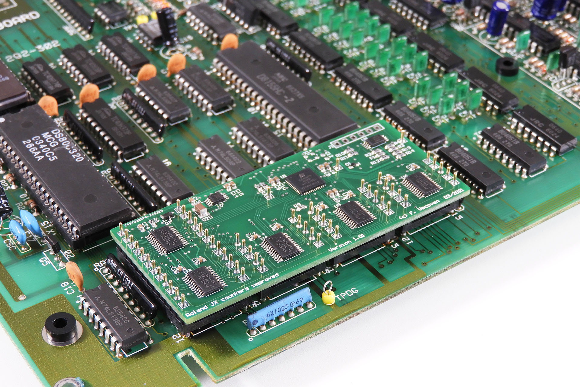
Vecoven Super-JX flash module (highlighted in red) installed in a Roland MKS-70.Voice boards lifted for a close-up view.
Well it just so happens that I also have a Roland MKS-70 (yeah, I know... you're really surprised, right?) and all this stuff just sounded soooo exciting. Within a few days, I ended up with a switched-mode power supply PCB and an OLED kit from Guy and a PWM kit and a Super-JX flash module from Fred. My wife wasn't happy.
And I thought lock-down was going to be oh soooo boring!
I had to buy all the components for the P0004 power supply but conveniently, Guy has a very detailed bill of materials (BoM) on his website. This made components purchase very easy. The OLED module came fully assembled and Guy e-mailed me instructions on how to install it. As previously mentioned, Fred's PWM kit doesn't include connectors and cables so I also had to buy some bits to get this going.
Getting to know Guy and Fred was a privilege. In fact, I eventually struck up a deal with Guy and I am now offering ready-built versions of his P0004 switched-mode power supply board, as well as an installation service for this fantastic upgrade and his Super-JX replacement displays.
If you're fitting the switched-mode power supply module yourself and your MKS-70 or JX-10 has a 2-pin IEC mains input socket, then you must replace it with a 3-pin IEC mains input socket. The replacement switched-mode power supply MUST be connected to earth as must the chassis of your Super-JX.
I offer a comprehensive earth bonding kit comprising the following:
1 x IEC 3-pin chassis socket.
1 x insulating boot for IEC socket.
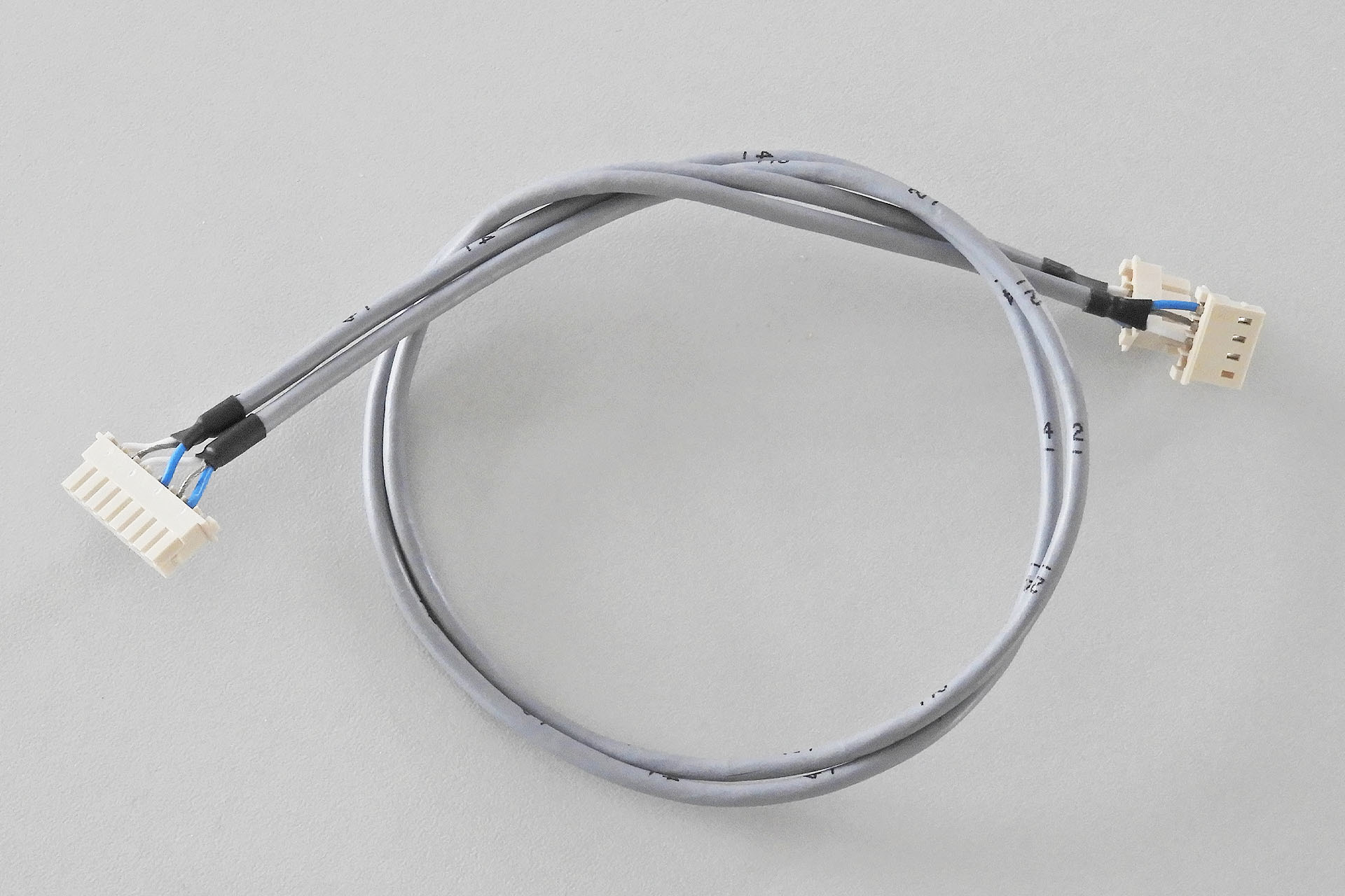
2 x Pre-cut earth leads terminated at one with earth tag.*
1 x M3 earth tag (for one side of IEC socket).
*One earth lead connects IEC earth to chassis via one of the screws that secures the IEC socket. The other earth lead connects the P0004 power supply to the chassis via any M3 screw.
It is paramount that if fitted, a 2-pin IEC C10 mains socket be replaced with a 3-pin IEC C14 mains socket and that the chassis and the P0004 are connected to earth.
Installing these Roland Super-JX upgrades into my own MKS-70, was hard work but I had a lot of fun doing it and... I got to know a couple of seriously intelligent dudes.
FOR YOUR INFORMATION
The IEC C14 socket that I use, is a drop-in replacement for the 2-pin IEC connector found on many Roland keyboards and rack modules. It is NOT necessary to drill, file, cut or modify the case to fit this IEC C14 socket.
A little known fact is that even keyboards with integral (hard-wired) power cables, have the power cable mounted to a metal bracket which is secured to the same screws holes and with the same type of screws, that are used on versions with IEC connectors! Behind that plate, is a cut-out for an IEC C14 connector.
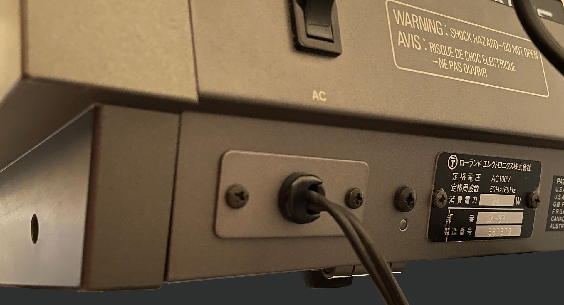
Below is an image of the back of a Japanese JX-8P with a hard-wired power cable. You can clearly see that the cable goes into a cable gland which is in a very IEC C14 sized metal plate. T H A N K Y O U, Roland!!!!
Even a hard-wired power inlet can be fitted with an IEC C14 power connector WITHOUT having to do any drilling!
My humble contribution to the awesome work that Guy and Fred have done, is a simple bracket which makes mounting the PWM boards into a MKS-70 a little easier. IMPORTANT:Since the bracket secures to the transformer mounting studs, it can only be fitted if Guy's P0004 switched-mode power supply is also installed.
Custom mounting bracket for Vecoven PWM kit in Roland MKS-70. The benefits of using this include no holes to be drilled in the voice-boards, makes general maintenance so much easier and of course your MKS-70 can be put back to factory any time.An elegant solution (even if I say so myself), my custom bracket makes installing the Vecoven PWM mod into the Roland MKS-70, so much easier.
The IDC connectors I've used, don't have the tidy fold-over clamp (retainer). That's because those ones are too high and this neat little mounting solution won't work as the whole assembly will simply be too high to fit in the MKS-70's 2U case.
The other point to note is that the V02 mounting bracket puts the Vecoven PWM daughter-boards, in very close proximity of the voice-boards. Hence and unlike if mounting the Vecoven PWM daughter-boards to the voice-boards, vertical and NOT right-angle IDC headers must be fitted to the PWM boards.
I wasn't going to offer this bracket as an item as it didn't seem worth it but I've been persuaded to get some made up and so I’m selling them with fixing hardware (screws, washers, spacers), as a kit for 27.60 GBP. If you fancy one, you can either buy now from here or just message me.
Note that the bracket isn't necessary when fitting the PWM kit into a JX-10.
Inspired by Guy's switched-mode power supply, I've proposed a couple of joint projects so watch this space!
!!! WORDS OF CAUTION !!!
These machines are over thirty years old. As such, nuts and screws have seriously bedded in. You may find some glue around the nuts and even some signs of corrosion.
If you're upgrading one of these machines yourself, please take care when undoing nuts and screws. The studs which secure the massive heat-sink plate of the original power supply and also the transformer for example, can become lose. When trying to remove the nuts on the inside of the chassis, they'll just spin around and they won't undo. If this happens, you'll need a pair of mole-grips to carefully hold the studs from underneath the case while gently loosening the nuts with a box spanner on the inside of the case.
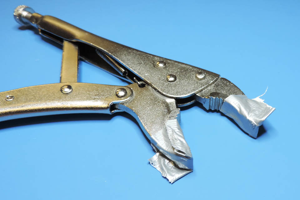
Mole grips can be a little aggressive so you might want to think about protecting the case with some thick tape. Put the tape around the lug of each stud and also put some tape on the tips of the jaws of the mole-grips. I found thick masking tape best for the case and lugs and cloth (or gaffer) tape is good on the mole-grips.
Doesn't look very pretty but helps protect your case.
When re-assembling, I would recommend replacing the nuts and soaking them in a lubricant like WD-40 prior to fitting.
!!! NOT FOR THE FAINT HEARTED !!!
The second point I should make is that with the exception of the Vecoven Flash module, all other upgrades mentioned here, require some considerable experience of soldering, desoldering, working with surface-mount devices and respecting electrical safety and electrostatic sensitivity. You should also be prepared to drill into existing PCBs and / or original chassis metal work.
!!! Remember, if you get it wrong, you might permanently damage your synth !!!
Today, my MKS-70 still looks pretty much as it did when my good friend Rob donated it to me, several months ago. Under the bonnet however, it’s quite a different beast. The sound is still lush and beautiful but...
As a result of installing Guy’s P0004 switched-mode power supply, not only has reliability and longevity been increased but this machine can be plugged straight into just about any mains supply on the planet.
The sounds can now benefit from pulse-width modulation thanks to the Vecoven PWM upgrade.
The Vecoven Super-JX flash module has increased the memory to a ridiculous amount; more patch changes and less SysEx transfers!
Firmware updates can now be performed over MIDI.
Guy's Super-JX OLED display looks quite simply, beautiful. To the experienced Super-JX user, it might be the only indication that something is err... different.
The Super-JX OLED will live much longer than the original VFD and FIP coil which can only give peace-of-mind.
Boot screen of fully upgraded Roland MKS-70.
LIVE FOREVER BATTERY MOD
This is something I do which isn't unique to the Roland MKS-70 and which can be fitted into almost any synthesiser or effects processor. It's NOT literally a 'Live Forever' battery mod as nothing obviously lives forever. The chances are however, that it'll out live you!
The damage caused by battery leakage can be irreversible. It's not just a case of losing all those tones and patches that you err... forgot to back up. Battery leakage can seriously damage the PCB on which the battery is mounted; usually the CPU board in most machines.
I mount a high-capacity lithium battery off any PCB giving you the following three main benefits:
Will last a lot longer than the standard CR2032 which is found in most synthesisers and effects processors.
Mounted off-PCB so in the remote event that it does leak, sensitive electronics inside your equipment is protected.
Positioned such that battery voltage can be easily checked by only removing the top of your machine.
If you missed it earlier, all my prices can be found here.
SUPER-JX EDITORS, CONTROLLERS, PROGRAMMERS
Anyone with a Super-JX will be aware of the Roland PG-800, a programmer / editor, specifically for the JX-10 and MKS-70. Today, PG-800s are hard to find, relatively expensive and quite honestly, you'd be lucky to find one in really good condition. I'm not talking cosmetically but electronically and it's worth bearing in mind, that parts are becoming ever scarcer.
Thankfully, a company called RetroAktiv makes a small collection of hardware programmer / editors for several popular vintage synthesisers... including our beloved Super-JX.
I don't have one of these myself but I've heard only good things about the RetroAktiv MPG-70. On top of that... damn, it looks good!
At 875 USD, the RetroAktiv MPG-70 costs a couple of hundred USD more than an original Roland PG-800. The thing is, even if you forget about the fact that this box is going to be considerably more reliable than thirty-something year old electronics, you're getting a lot more for your money and (I'm going to say it again) it just looks awesome.
If you're still not convinced, then RetroAktiv also makes a smaller Super-JX editor called the MPG-8, which retails for just 349 USD.
One of the many features of both of these controllers, is full compatibility with the Vecoven PWM upgrade and firmwares.
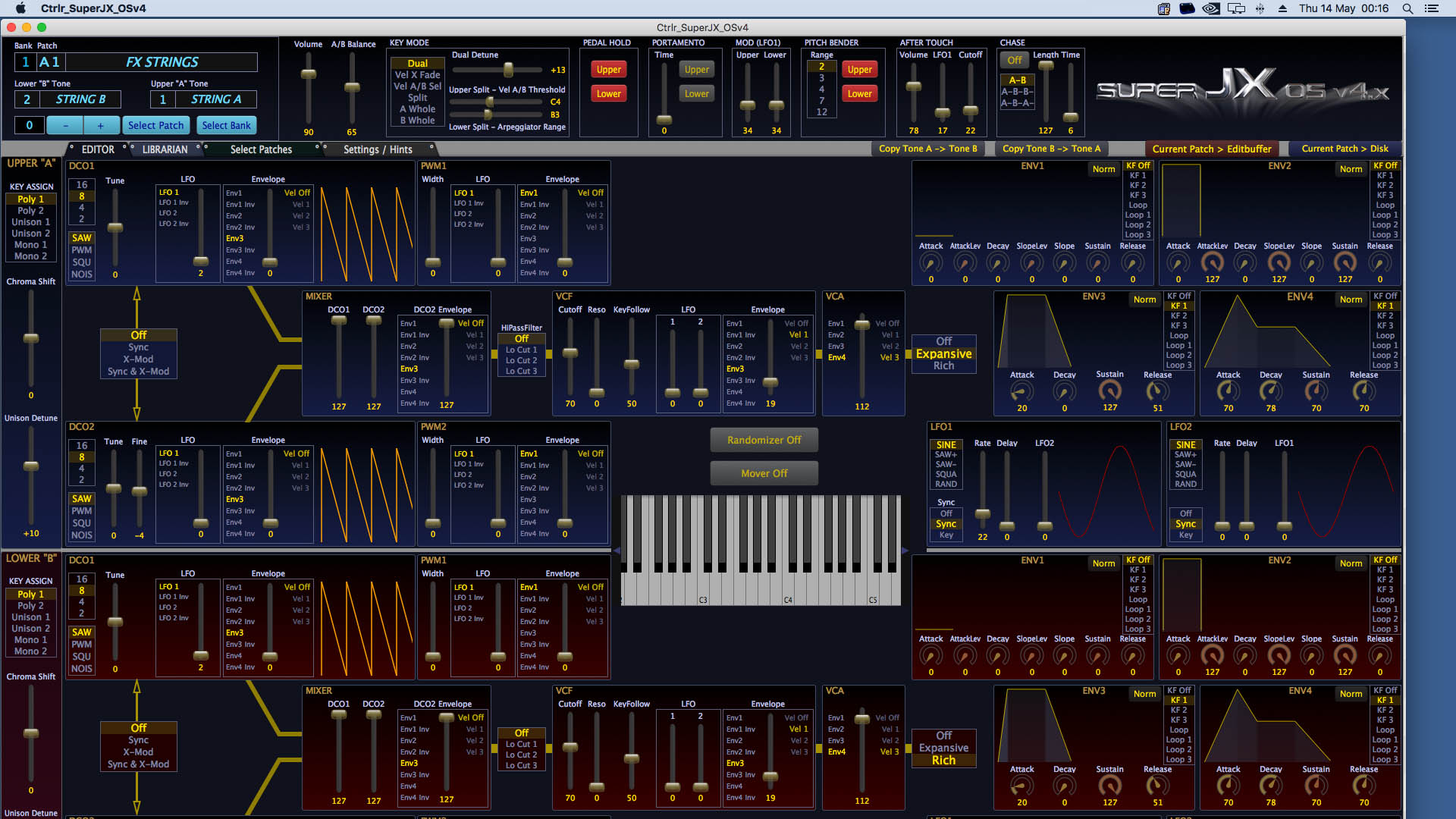
For some time now, I've been using a plug-in called Ctrlr. It’s basically an open-source environment for Windows, OS X and Linux, which allows users to develop programmers and editors for just about anything. Many users share their ‘panels’ on the Ctrlr website and I was so surprised to find a panel specifically for the Vecoven V.4 firmware upgraded Roland Super-JX. This doesn't really fall into the category of Roland Super-JX upgrades as such but I think it still deserves a mention. Available for Windows and OS X, 32 or 64-bit and in plug-in or stand-alone format, you really need to check this out. Oh and it's free! 😀
The RetroAktiv programmers will work with Super-JXs running standard (factory) firmware although some sliders and knobs won't do anything as there's no PWM to modify, for example. The Ctrlr panel above will ONLY work with Vecoven version 4 firmware. While I've seen Ctrlr panels that'll work with Vecoven version 3 firmware, I haven't come across anything that'll work with bog standard Roland firmware.
It's been most reassuring to discover that I'm not alone, that there's a whole community out there that share my appreciation and even passion, for this underrated monster of a synthesiser. I'm so grateful to people like Guy, Fred and the RetroAktiv crew, who after more than thirty years from it's launch, have embraced the potential of the Roland Super-JX, developing upgrades that ensure this magnificent machine lives on.
I'd love to contribute what I can so please don't hesitate to contact me if you'd like more information on any of the Roland Super-JX upgrades mentioned here. I'd love to hear from fellow fans of this awesome synth. 😎
In the meantime, here's a few links that you might want to check out:
https://supersynthprojects.com - This is Guy Wilkinson's website full of seriously useful information about the Roland Super-JX.
Wow! Since I put up this post, things have got a little busy.
Three MKS-70s and yes, well done! You've spotted the MKS-80 in the foreground.This machine is having my Super-JX upgrade bundle fitted.
UPDATE - 17th August 2021
This is Nebula, a new jack board for the Roland MKS-70 with upgraded MIDI and balanced outputs.
Today I launched Nebula, a replacement jack-board for the MKS-70 with upgraded MIDI and balanced outputs. Read all about it here.
UPDATE - 9th June 2022
I'm a big believer in the saying "If it ain't broke, don't fix it". On the other hand, isn't wisdom all about taking action before stuff goes wrong?
Today I had the most terrible job of telling a customer that the only way he's going to get his MKS-70 up 'n' running, is by acquiring a new assigner board. 🙁
Yet another PSU failure and yet another totally scrapped MKS-70. You simply might not be interested in all these upgrades but PLEASE...
GET A P0004 POWER SUPPLY BEFORE IT'S TOO LATE!!!
UPDATE - 19th June 2022
I've been meaning to add this update for months so finally...
A few months ago, Fred Vecoven launched his digital PWM upgrade. It's brilliant! You can read more about it here.
Simple and elegant, Fred Vecoven's new digital PWM upgrade for the Roland Super-JX is quite simply beautiful.
UPDATE - 21st May 2023
Over the past few weeks, I've been busy developing a FSR-based replacement aftertouch sensor for the Roland JX-10 and today I had the pleasure of having my friend Guy Wilkinson come over to collect his JX-10.
Alex, Guy and Roland JX-10... now with fully working aftertouch.
Guy was kind enough to lend me his synthesiser so that I could develop my AT-JX-10.
After playing with his JX-10 for a while, Guy said that he's now smiled nine times this week! 🙂
Over the past few days, I've been experimenting with replacing the wires that connect the module-boards to the jack-board, in the Roland MKS-70, with screened cables.
It's not as simple as it might sound. To start with, I needed a tool that cost over 400 GBP. I also needed to carefully consider some aspects of the original connection.
Perhaps the most boring thing I've ever photographed! My screened audio cables for the Roland MKS-70.
After some tests and experiments however, I'm delighted to announce that my screened audio cables for the Roland MKS-70 are now available in my e-store. You can read more about this easy to install upgrade, here.
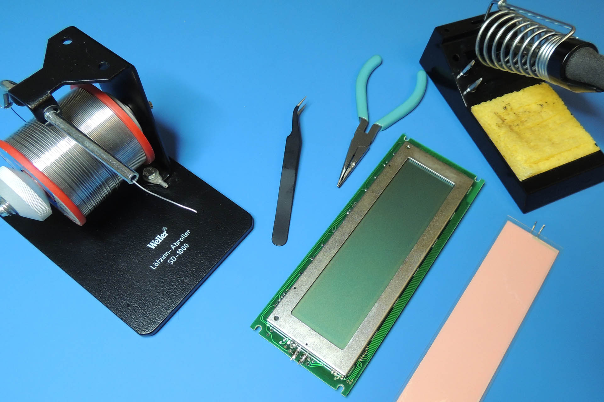
A relatively common problem on older equipment, is the failure of the LCD backlight (or EL-panel). Often accompanied with a very high-frequency whine emanating from the LCD area of the gear in question, it's time to consider an EL panel and inverter replacement.
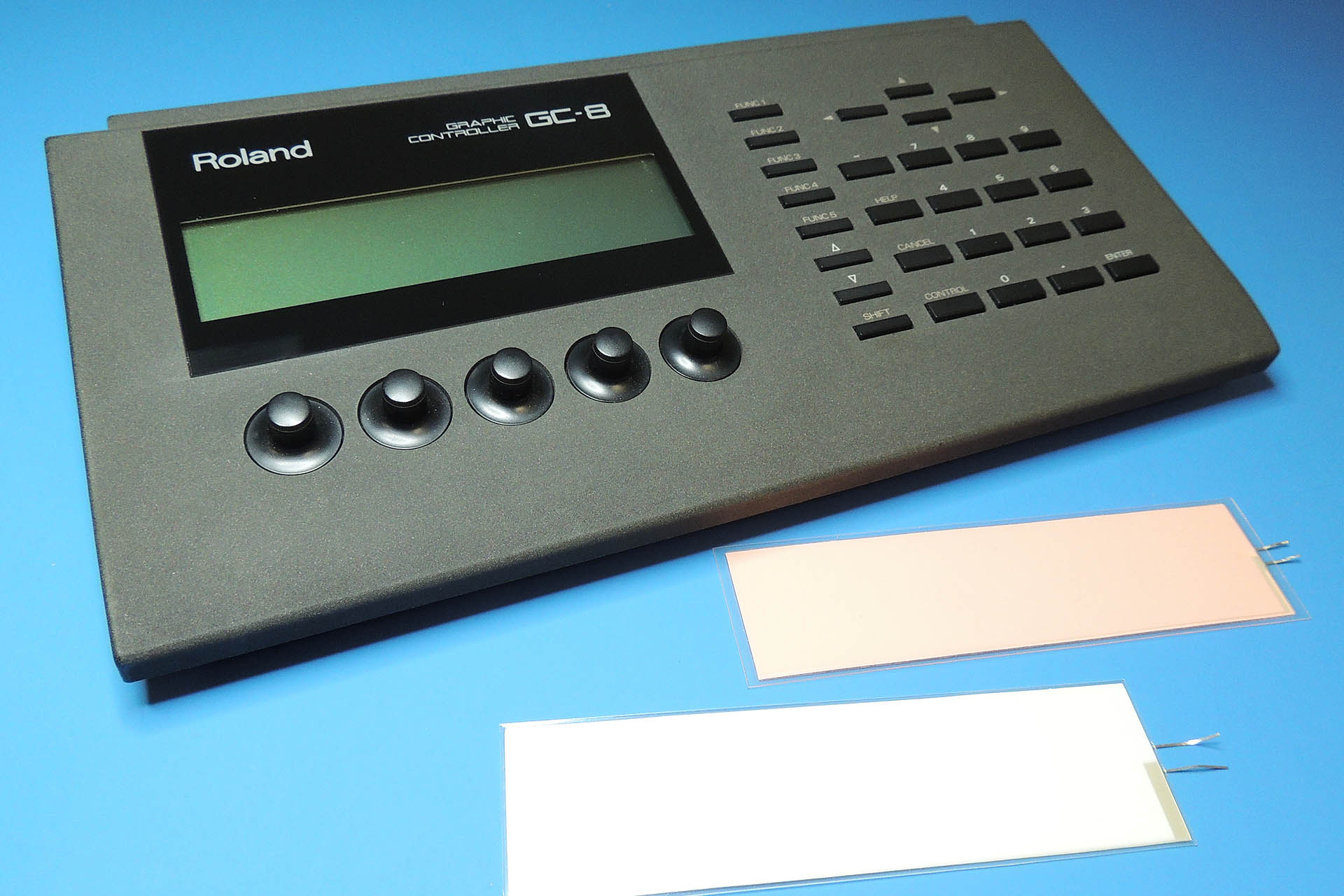
Here's a Roland GC-8 editor / controller for the massive Roland R-880 reverb (circa 1988). Without the controller, the R-880 which really is an awesome machine, is kind of useless as there's little out there to program it via MIDI.
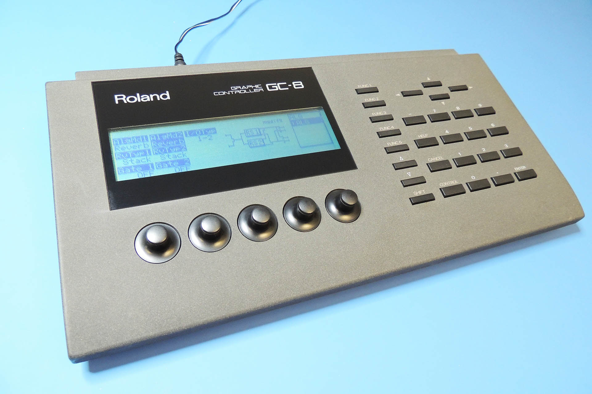
Roland GC-8 with original LCD backlight (pink) and new LCD backlight.
Luckily and thanks to a company called backlight4you, LCD backlight replacement is now worth looking into. A variety of EL-panels that are suitable for a whole bunch of older gear, is available at the company's website which is also full of other useful and related information. Their backlights are reasonably priced and arrive from Germany pretty quickly and in very stiff cardboard packaging.
After fitting the replacement EL-panel, I powered up the unit to check. Wow! It looks great and on this occasion I got lucky and that bloody annoying whine has gone!
IMPORTANT:As a backlight ages, its electrical characteristics change, These changes put a strain on a small circuit called an inverter which converts dc within the unit to high-frequency ac which is required to drive the EL-panel. As parts of this circuit age, it starts to whine. In many cases, replacing the backlight will fix that problem but... not always. : (
If after swapping out your backlight, your unit is still whining, then backlight4you may still be able to help. Take a closer look at their website and you'll find a section on inverters. Designed to run from common voltages and power many of the EL panels that are sold on the website, these replacements are very reasonably priced.
Replacement inverters might not be pin-for-pin compatible, especially with very old equipment but with a little ingenuity, you might be able squeeze one in somewhere.
Due to the low cost of replacement inverters, I would personally recommend swapping out the inverter if possible, when fitting a new EL-panel.
Several days after replacing the EL backlight panel in this Roland GC-8, the high-pitch whine started again. I decided to go back to backlight4you and check out the inverters that are advertised on the company's website.
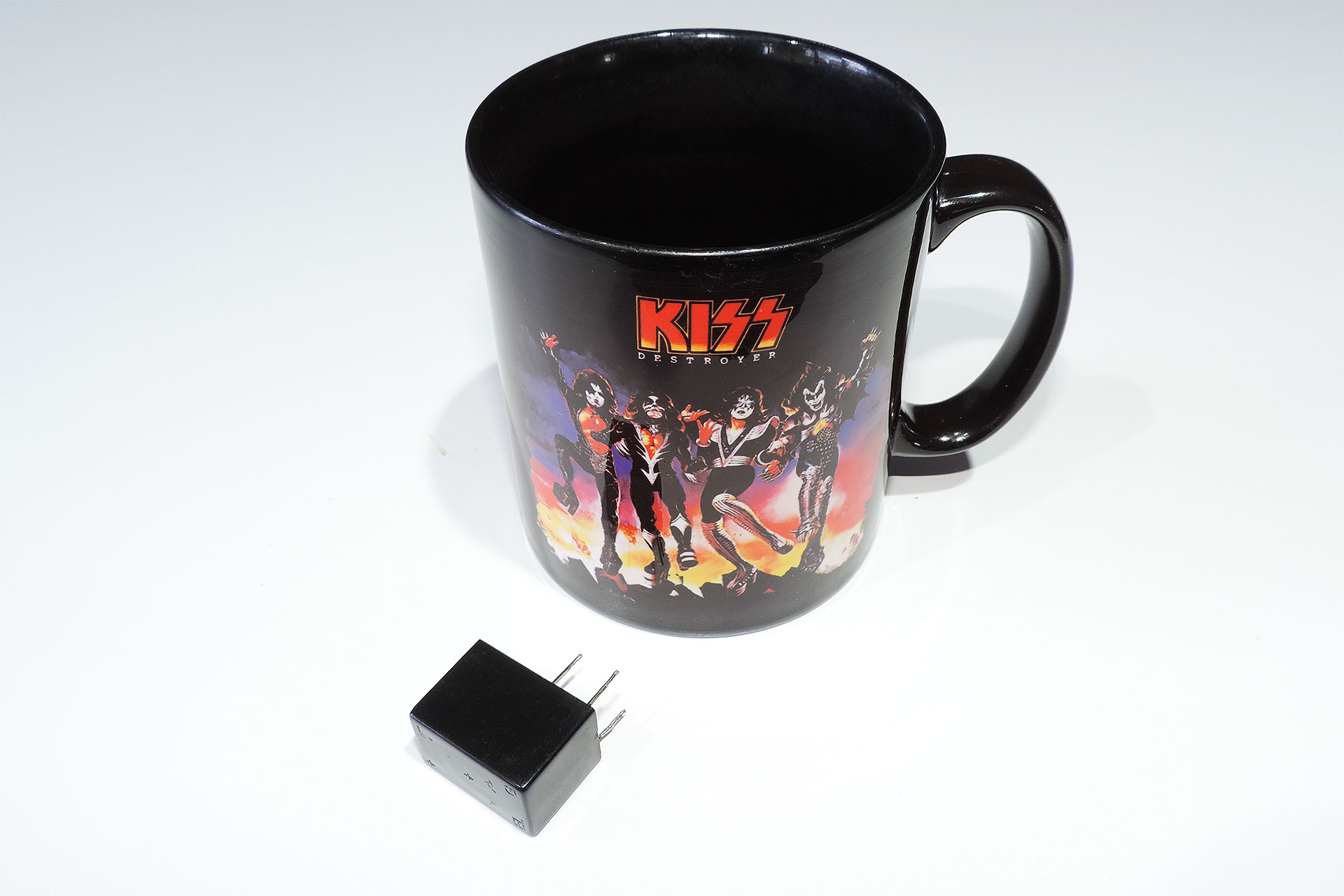
Due to the limited space inside the GC-8, I needed something small and indeed the backlight4you inverters do look as small as you can get them.
EL inverter from backlight4u scaled against my favourite coffee mug!
While waiting for the inverter to arrive, I removed the original transformer from the GC-8 inverter circuit. This is the component that actually generates the whine.
When the inverter did turn up, it was quite obvious that it wouldn't fit straight on to the GC-8's PCB. I expected as much but I'm stating this for clarity to others. I ended up placing the inverter, underneath the main PCB towards the sockets at the back of the GC-8. Phew! It just fitted. The slanted profile of the unit meant that it wouldn't fit towards the front where there's a bit more room. Typical!!!
Connecting the 3-terminal device was straight-forward and since my GC-8 isn't going on an interplanetary mission in the near future, securing it just needed a little double-sided tape and hot glue.
It's important to note that this little black epoxy resin box, is a complete inverter and NOT just the transformer.
Time to power up and test. DEAD quiet! Wow, this is definitely worth doing.
I actually have two Roland R-880s and so, two GC-8s. My EL panel and inverter replacement on one of my units, meant that well, I just had to do the other one, too! 🙂