So in case your Marshall JMP-1's memory gets screwed up, if you just want to start from a clean slate or you've just changed the memory back-up battery, here's the Marshall JMP-1 factory reset procedure.
WARNING: Implementing this procedure will permanently delete all user-made changes to any patches.
Switch off JMP-1 via the power button on the far right.
Hold down the <OD 1> button and the <Clean 1> button.
While holding down these buttons, switch on the JMP-1.
Wait a few seconds while the display flashes and then release the OD 1 and Clean 1 buttons.
Now then, you're JMP-1 might NOT reset! Yes, that's right. If your machine is locked, performing a factory reset will be useless until you unprotect your JMP-1's memory.
To check the memory protect status of your JMP-1, simply try to save a patch. If the display shows 'St L', then your JMP-1 is locked and you will need to unlock it prior to performing a factory reset.
Unlocking is simple. Just follow this procedure:
Try to save a patch.
While 'St L' is displayed, press the <CHANNEL> button.
The unit will unlock.
You can now perform a factory reset as above.
MARSHALL JMP-1 MEMORY BULK DUMP
While you're here, you may find it useful to know how to dump the entire memory of your JMP-1 to a sequencer or sysex package like MIDI-Ox or SEND-SX.
Just connect the MIDI OUT from your JMP-1 to the MIDI IN of your sequencer or computer's MIDI interface.
If using a computer, select that port in your sysex package.
Now just press <Patch> and <Volume> simultaneously on your JMP-1.
I hope this Marshall JMP-1 factory reset procedure helps a few people but if you get seriously stuck, just message me. 🙂
If you want to read more about what I do with JMP-1s, like general service and repair, finding a permanent solution for the skipping data entry knob thing, sorting out the humming transformer issue and offering nice, classy replacement knobs, then please check out some of my other posts:
Apart from service and repair, I sell a few bits 'n' pieces for the Marshall JMP-1 which you may find of interest. Check out my on-line store to find out more.
UPDATE - 21st September 2021
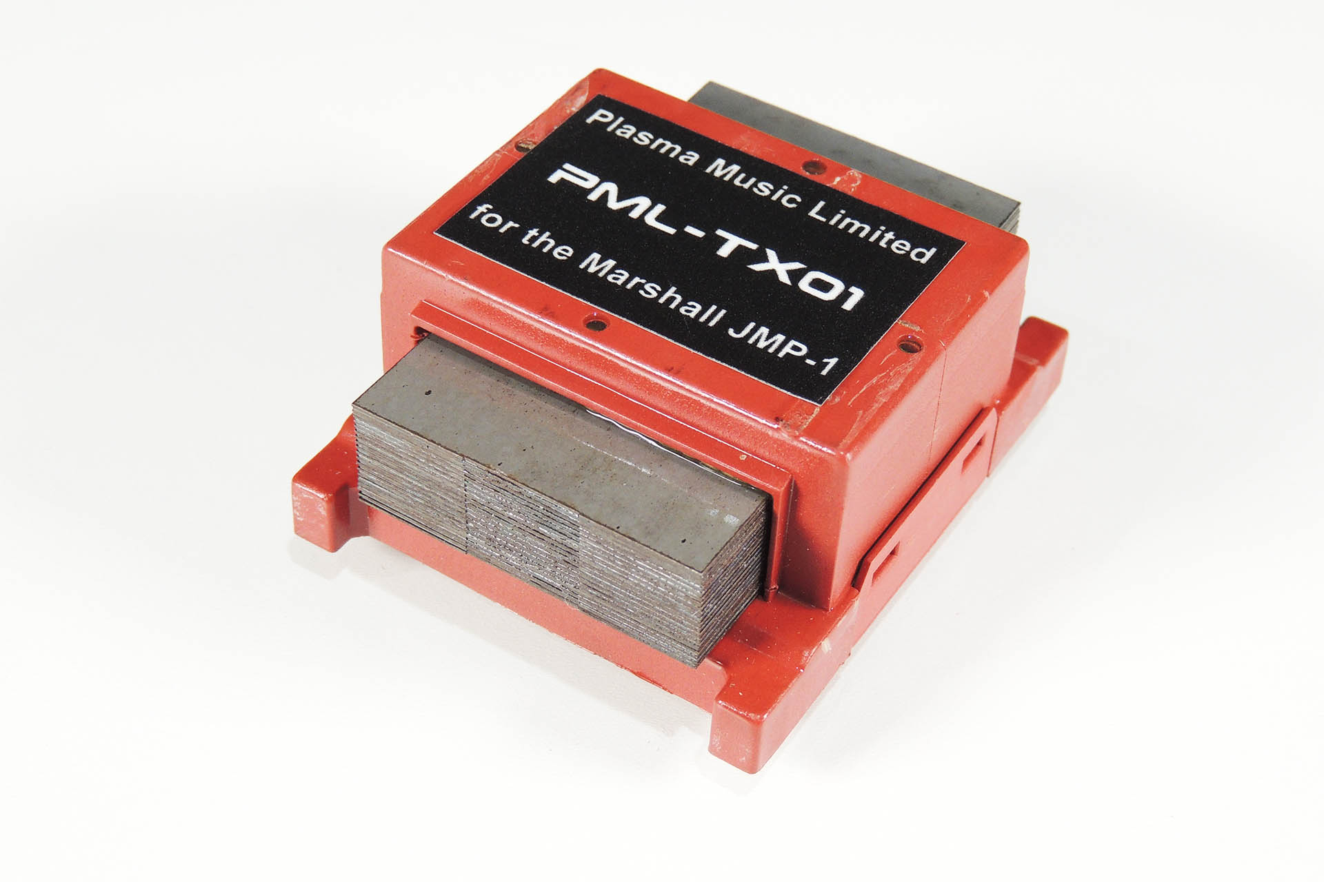
At last!!!! 😀 My PML-TX01 replacement (and upgraded) transformer for the Marshall JMP-1 is finally here! Running much cooler and producing considerably less hum than the original TXMA-00014 my PML-TX01 is an upgrade worth considering.
And here it is... my PML TX-01 transformer for the Marshall JMP-1
UPDATE - 20th July 2023
I've just brought out an adapter which fits into the location of the JMP-1's battery and allows a standard CR2032 battery to be installed. 🙂 You can read all about here.
UPDATE - 8th February 2024
At last! rack-ear reinforcement brackets for the JMP-1 are on the way!!! 😀 People have been asking me for these for a long time so what the hell... let's get them made.
UPDATE - 9th February 2024
Well, I guess I have to admit that I can't help developing stuff for the Marshall JMP-1. So to make life easier for everyone, I've now got a Marshall JMP-1 category in my on-line store!
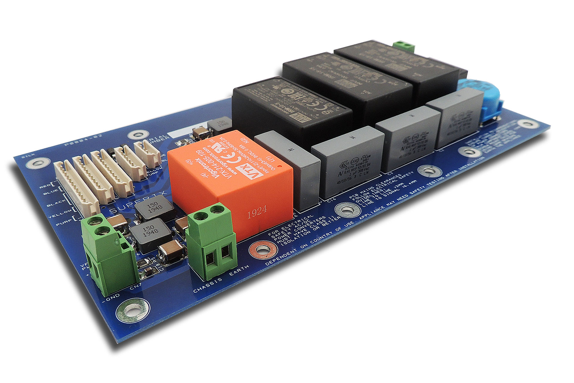
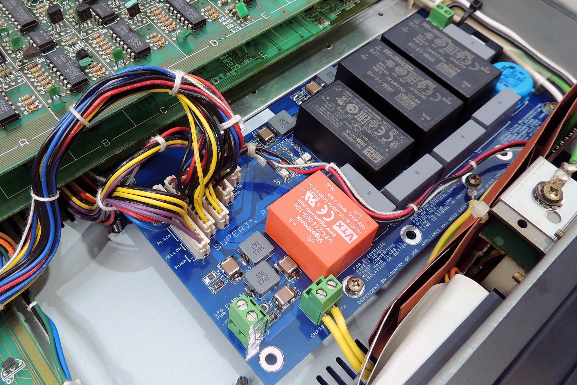
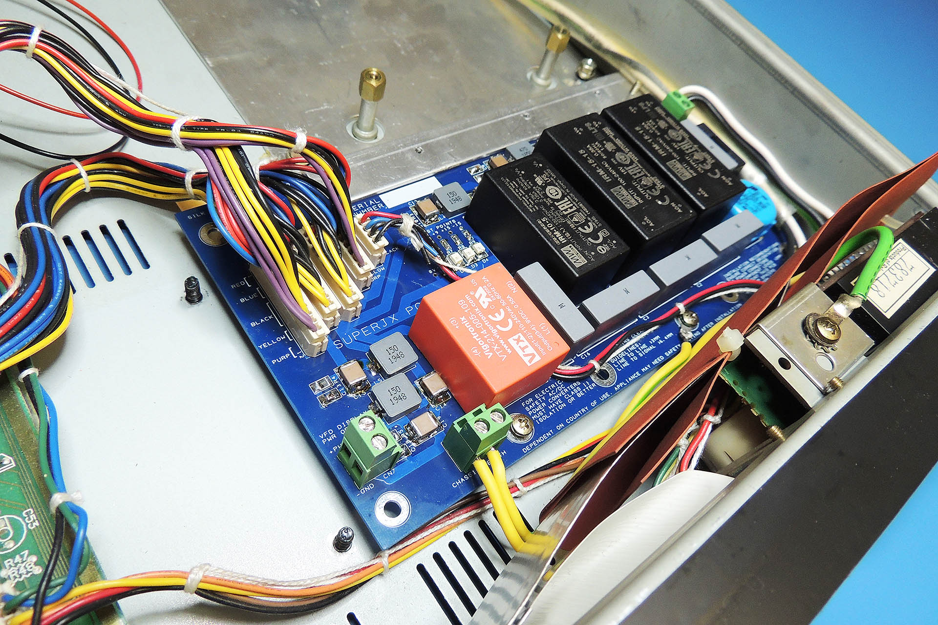
Guy Wilkinson's P0004 switched-mode power supply for Roland Super-JX.
Never thought I’d make a new friend over lock-down but I have recently struck up a relationship with Guy Wilkinson of supersynthprojects.com.
While working on a very broken Roland MKS-70 that I have in for repair, I came up with the idea to design a MKS-70 power supply replacement but figured that after all these years, perhaps someone has already thought of this. After a few minutes of searching on-line, I stumbled across https://supersynthprojects.com. The work that Guy has done, is truly amazing. His power supply design is quite simply, elegant and I’m so impressed with his methodical record keeping. As it turns out, Guy seems to be a bit of an expert on several vintage machines.
Anyway, having a Roland MKS-70 myself, one thing led to another and I’m currently in the process of building one of Guy’s P0004 switched-mode power supplies and installing his Super-JX OLED display module into my own MKS-70. It’s a bit difficult doing this during lock-down but I’ll keep you posted of progress.
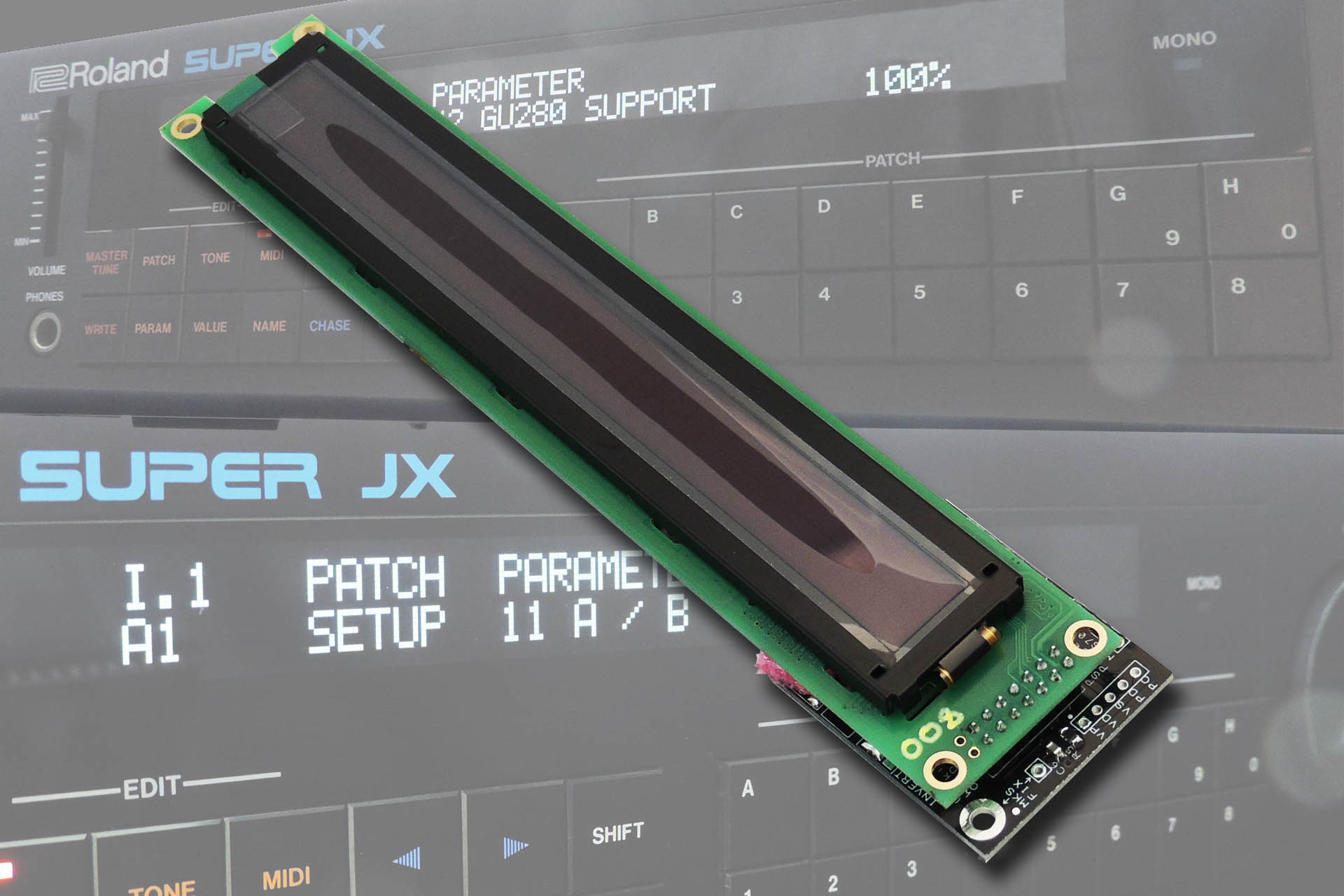
Guy Wilkinson's Super-JX OLED module. The background images show an actualSuper-JX OLED installed in a Roland MKS-70.
Guy sells the P0004 switched-mode power supply bare PCB and the pre-assembled Super-JX OLED display directly but you'll need some competence to populate the former and fit either, into a JX-10 or MKS-70. If you're cool enough to admit that all of that sounds a bit too much for you, then please don't hesitate to contact me to discuss getting either (or both) fitted into your machine.
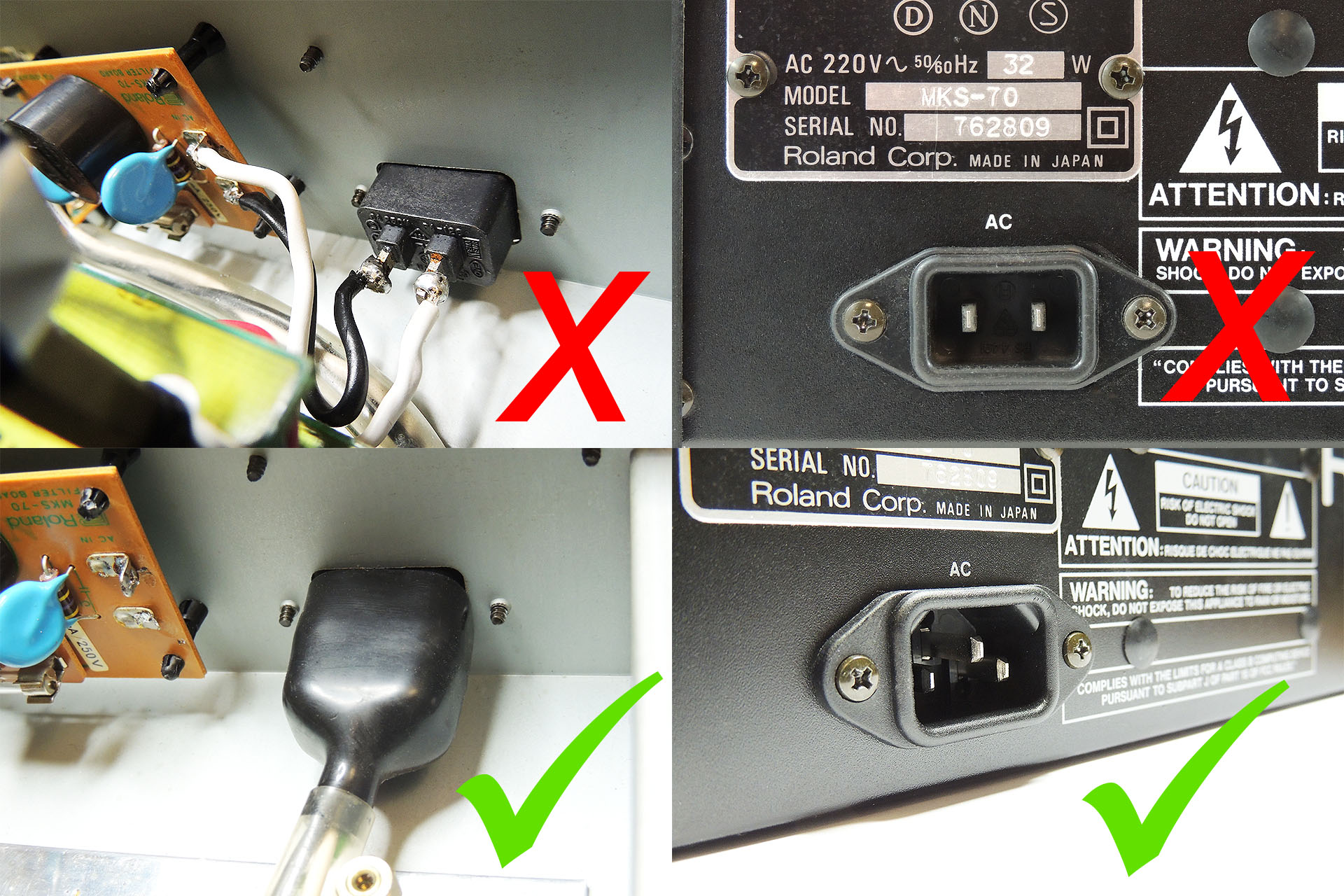
If you're fitting the switched-mode power supply module yourself and your MKS-70 or JX-10 has a 2-pin IEC mains input socket, then you must replace it with a 3-pin IEC mains input socket. The replacement switched-mode power supply MUST be connected to earth as must the chassis of your Super-JX.
I offer a comprehensive earth bonding kit comprising the following:
1 x IEC 3-pin chassis socket.
1 x insulating boot for IEC socket.
2 x Pre-cut earth leads terminated at one with earth tag.*
1 x M3 earth tag (for one side of IEC socket).
*One earth lead connects IEC earth to chassis via one of the screws that secures the IEC socket. The other earth lead connects the P0004 power supply to the chassis via any M3 screw.
It is paramount that if fitted, a 2-pin IEC C10 mains socket be replaced with a 3-pin IEC C14 mains socket and that the chassis and the P0004 are connected to earth.
FOR YOUR INFORMATION
The IEC C14 socket that I use, is a drop-in replacement for the 2-pin IEC connector found on many Roland keyboards and rack modules. It is NOT necessary to drill, file, cut or modify the case to fit this IEC C14 socket.
A little known fact is that even keyboards with integral (hard-wired) power cables, have the power cable mounted to a metal bracket which is secured to the same screws holes and with the same type of screws, that are used on versions with IEC connectors! Behind that plate, is a cut-out for an IEC C14 connector.
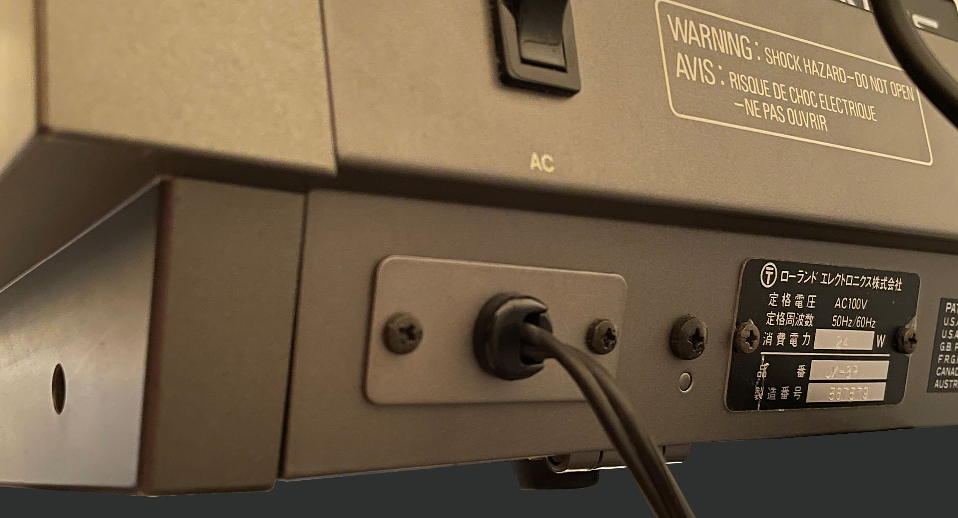
Below is an image of the back of a Japanese JX-8P with a hard-wired power cable. You can clearly see that the cable goes into a cable gland which is in a very IEC C14 sized metal plate. T H A N K Y O U, Roland!!!!
Even a hard-wired power inlet can be fitted with an IEC C14 power connector WITHOUT having to do any drilling!
UPDATE - 10th MAY 2020
Last night I installed the assembled switched-mode power supply into my own Roland MKS-70. I'd already tested it outside the machine but I was still nervous. Hey, the MKS-70 fired up straight-away. The power supply worked just fine and quite honestly, if you're having issues with the power supply in your Roland MKS-70 or JX-10, then getting one of these is a no-brainer!
Look, no transformer! Coooool.
UPDATE - 12th MAY 2020
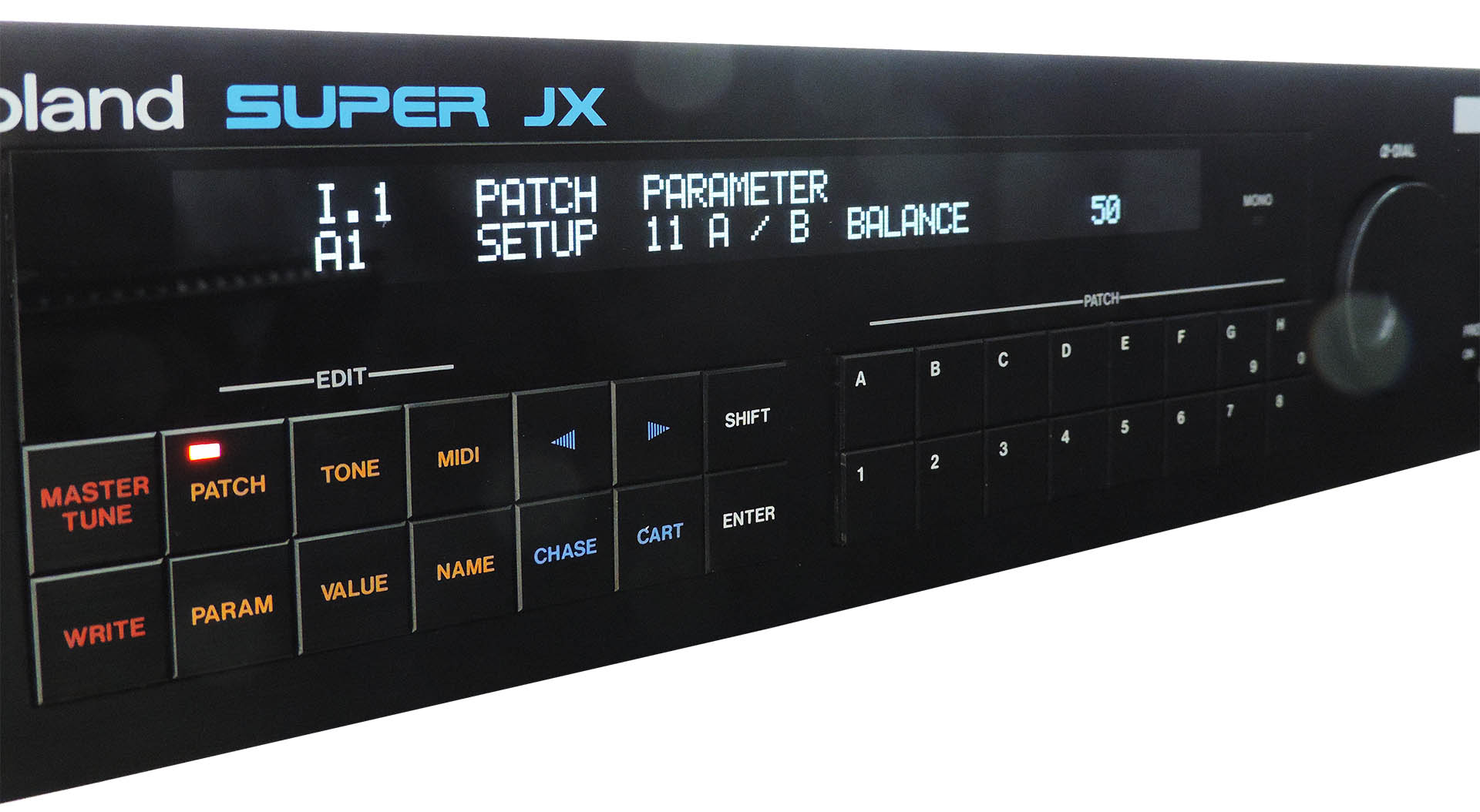
Took a while and was a bit tricky but the display got done and works absolutely brilliantly (pardon the pun). In fact it looks positively beautiful.
Never knew what people meant when they referred to tech as "sexy". Now I do. I can't stop looking at it!!!!
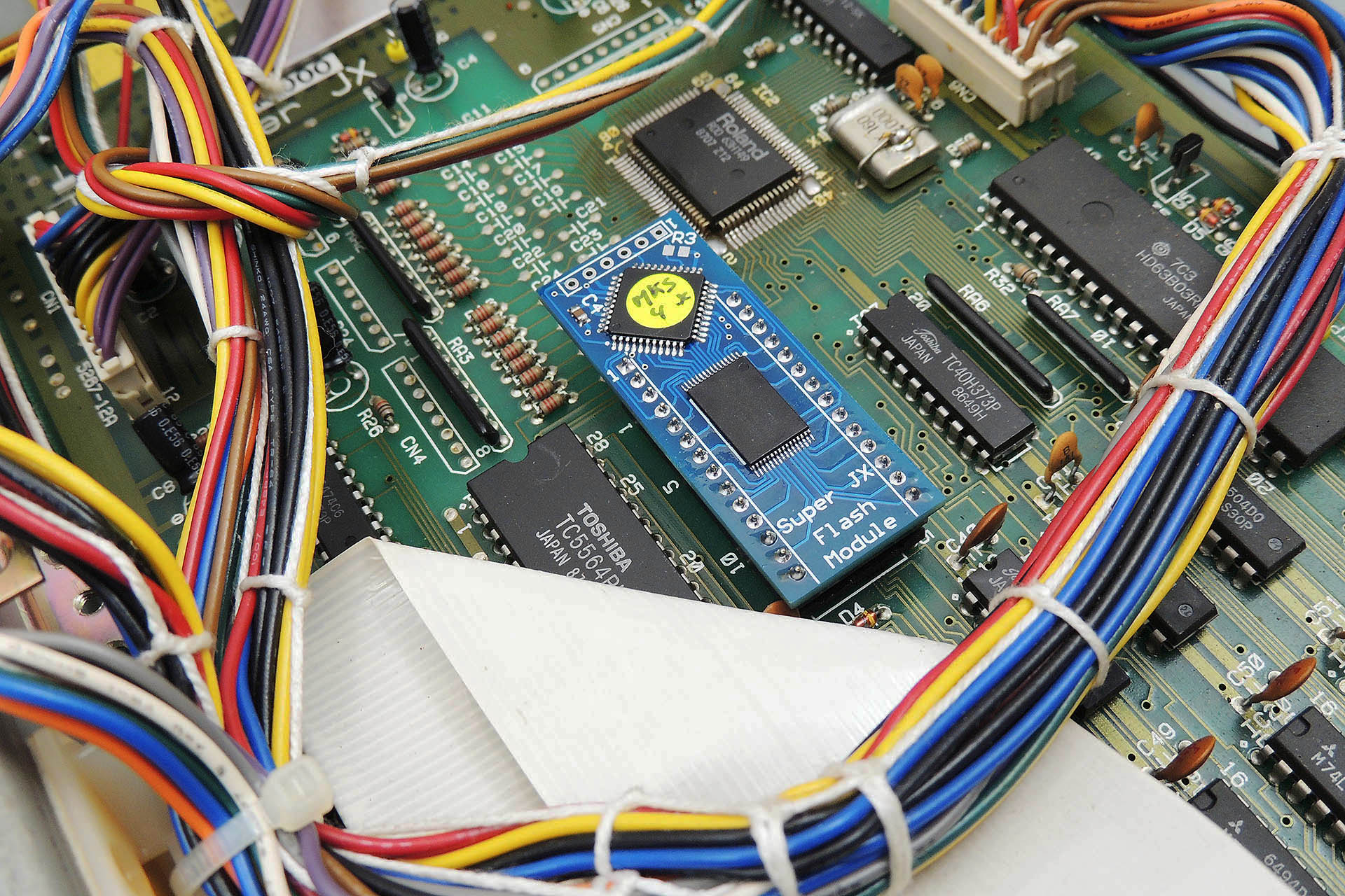
The Super-JX OLED module 'learns' the system's firmware so before I switched on the unit to test, I thought I'd drop in the Vecoven Super-JX flash module. Pressed the power button and everything powered up just great.
UPDATE - 19th MAY 2020
Several days ago, I posted here that I'd keep you updated of progress on this project. I also suggested that I'd probably end up making a new post. Guess what? So, click here for more on Roland Super-JX Upgrades.
UPDATE - 9th June 2022
I'm a big believer in the saying "If it ain't broke, don't fix it". On the other hand, isn't wisdom all about taking action before stuff goes wrong?
Today I had the most terrible job of telling a customer that the only way he's going to get his MKS-70 up 'n' running, is by acquiring a new assigner board. 🙁 That basically means buying a new MKS-70!
Yet another PSU failure and yet another totally scrapped MKS-70.
I can't emphasise this enough;
GET A P0004 POWER SUPPLY BEFORE IT'S TOO LATE!!!
Look, there are two MASSIVE hidden bonuses when using something like Guy's P0004 power supply;
Unlike the original Roland PSU, the +5V supply on the P0004, is NOT derived from the +15V line and is fully independent. Hence, any fault on the +15V line, won’t affect the +5V supply.
In the event of a failure, the respective supply will simply stop working and chuck out 0V.
Big deal, so... Well, sadly, I occasionally see a MKS-70 which has had a failure of the +5V supply. If the failure is as a result of the +15V going wacky, this often results in the +15V line jumping to like +22V, thus maxing out the +5V regulator circuitry and taking out your assigner board. That’s basically a bricked MKS-70! 🙁
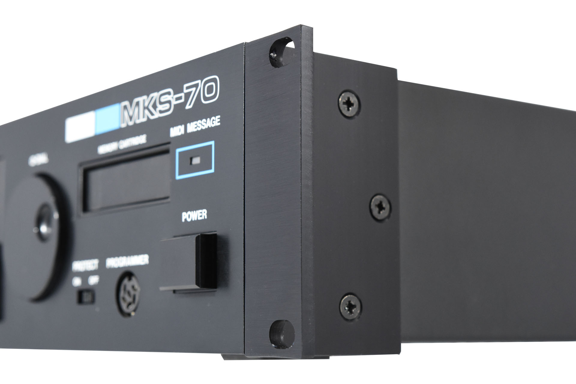
Recently, this gorgeous vintage Roland MKS-70 synth module came in for repair.
The MKS-70 is basically the rack version of the Roland JX-10 keyboard synthesiser, which itself is essentially two JX-8Ps. Also known as the Super-JX, the JX-10 and the MKS-70 are famous even today for their rich, analogue tone and pristine sound quality. At this point I need to make something clear; the Super-JX is not actually 100% analogue unlike for example, one of it's well known predecessors, the MKS-80. The oscillators are in-fact, digital. So when I refer to 'analogue' tone, I'm referring to just that, the tone.
Check out more details and some sounds here and here.
Anyway, the customer said that it wasn't powering up properly with just a flash briefly appearing on the display and then nothing. Well, let's see if we can get this ol' girl singing again..
Apart from being a giant classic, the MKS-70 like the MKS-80, has hinged circuit boards which means that it opens up quite nicely. Having said that, if you need to get at the 'CPU' board (the service notes refer to this as the assigner-board, for some reason), you really do need to disconnect and remove the lower analogue voice-board.
Checking voltages before anything else, I realised very quickly that I had a major problem. The voltages on the power supply were all about 25% more than what they should be. Eek! Hope no serious damage has been done.
I'll keep you posted on this fix but please bear in mind that I'm respecting the COVID-19 lock-down so it may be a while before I'm back.
UPDATE - 2nd April 2020
The power supply is a really clever and well thought out design for the time but I don't think the Roland R & D team had any idea that their machines would still be making music over thirty years after their conception. There's a small voltage monitor / management chip on the power supply which, when it fails, sends the +/-15 V rails to like +/-22 V. Unfortunately the +5 V rail for the digital stuff has a dependency on the +15 V rail so if that freaks out, then so does the +5 V supply. That's seriously bad news for the MKS-70's assigner-board. 😒
I decided to change all the major components on the PSU including transistors, capacitors, bridge rectifiers and of course that frigin' voltage controller IC. Okay, so now power is good.
UPDATE - 14th April 2020
Well the voice-boards turned out to be fine but the CPU or assigner-board, was seriously not happy. The code was trying to run but not getting anywhere. My worst fears an' all that... This was not going to be a straight-forward Roland MKS-70 repair!
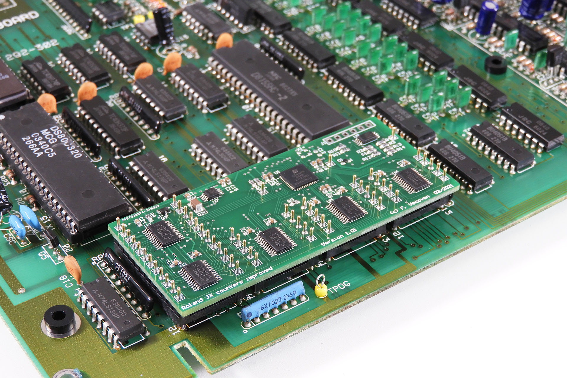
Using Fred Vecoven's Super-JX flash upgrade module meant that the assigner-board could be tested without having the voice-boards connected. Wow!
I'll get back as soon as I get somewhere... or not.
UPDATE - 14th January 2021
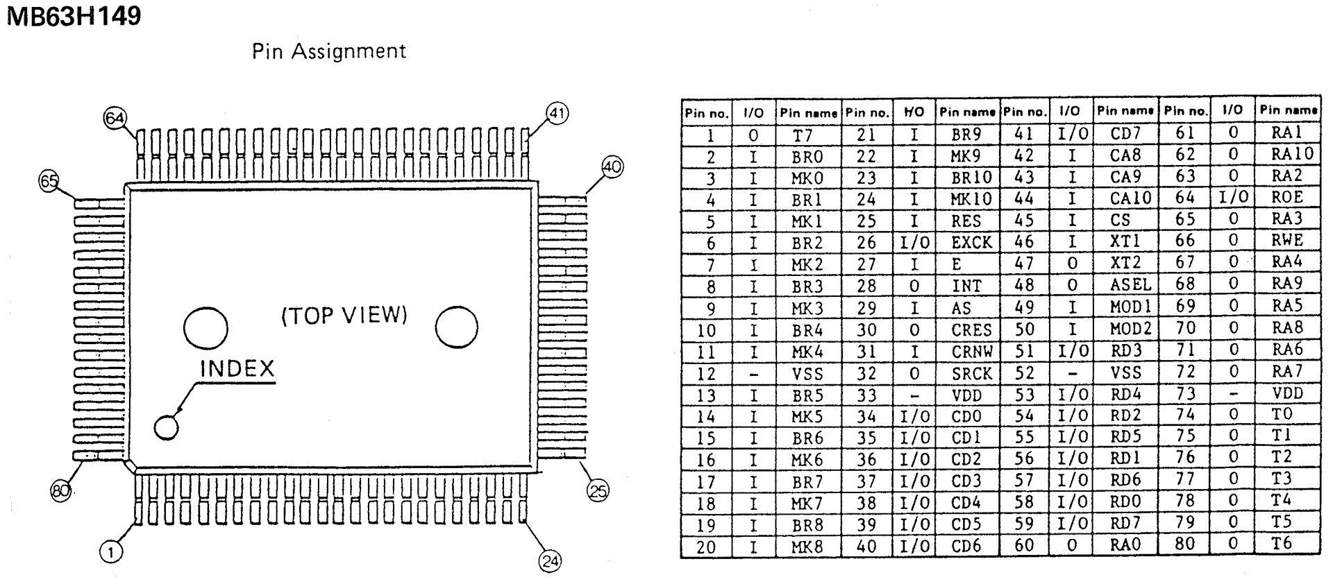
The assigner-board on this Roland MKS-70 is indeed kaput. Having got to know Guy Wilkinson of SuperSynthProjects over lock-down 2020, Guy came over when things calmed down and we both agreed that although laborious, one coarse of action would be to swap out all of the ICs but... as many will know, there's one IC that can't be replaced too easily and that's IC2, the 63H149 proprietary Roland gate array.
The proprietary 63H149 gate array IC found in many 80's Roland synths and modules is impossible to replace now-a-days.
The 63H149 is used in a lot of Roland keyboards and modules, right up to the S-10 and the D-50. In many machines, including the keyboard version of the MKS-70, the JX-10 the 63H149 is mainly used as the keyboard scanner but unfortunately, it's also quite connected to other devices in the MKS-70.
Guy came up with an idea and is currently in the process of designing a 'replacement' for the 63H149. This isn't going to be a drop-in 80-pin device like the 62H149 itself but something that will kind of 'bypass' the chip's functions and fool the MKS-70 into thinking that the gate array is there and functioning normally. If we can do this, it'll be quite a break-through and will potentially save a lot of MKS-70s.
An exciting but time-consuming project, it's going to take a while but be sure that I'll definitely keep you posted.
Please don't hesitate to contact me if you have a sick Roland MKS-70 or any other vintage synth.
UPDATE - 12th June 2021
It's been several months since my last update on this. Guy and I have been working on a project to bypass the Roland 63H149 chip which seems to be the problem in this particular MKS-70. The project is quite consuming and of course, my customer was anxious. Luckily, I found a brand new 63H149 for sale and snapped it up.
Replacing devices like the 63H149 is a daunting prospect but it had to be done suffice to say that once the new chip was installed, the MKS-70 booted! 😮
UPDATE - 28th October 2025
It's been more than five years since I posted this article. Since then, I've received so many MKS-70s from all over the world and designed a whole load of peripherals for one of our favourite analogue synthesisers.
It now seems that I always have at least a couple of MKS-70s in the lab!
To try to avoid having to go through the above, I now tell all my Super-JX customers to strongly consider replacing the power supply in their instruments with Guy Wilkinson's P0004 modular switched-mode power supply.
P0004 modular switched-mode power supply for the Roland MKS-70 and JX-10.
Of course, Fred Vecoven's PWM upgrade has now evolved into a much easier (and hence cheaper to install) digital version and Guy Wilkinson's OLED and GU-280 displays are complete life-savers.
Simple and elegant, Fred Vecoven's new digital PWM upgrade for the Roland Super-JX is quite simply beautiful.
Fred's Super-JX Flash Upgrade not only replaces the firmware of the Super-JX with something a lot more reliable and versatile but it also gives these instruments a massive onboard memory, basically negating the need for storing data on a memory cartridge.
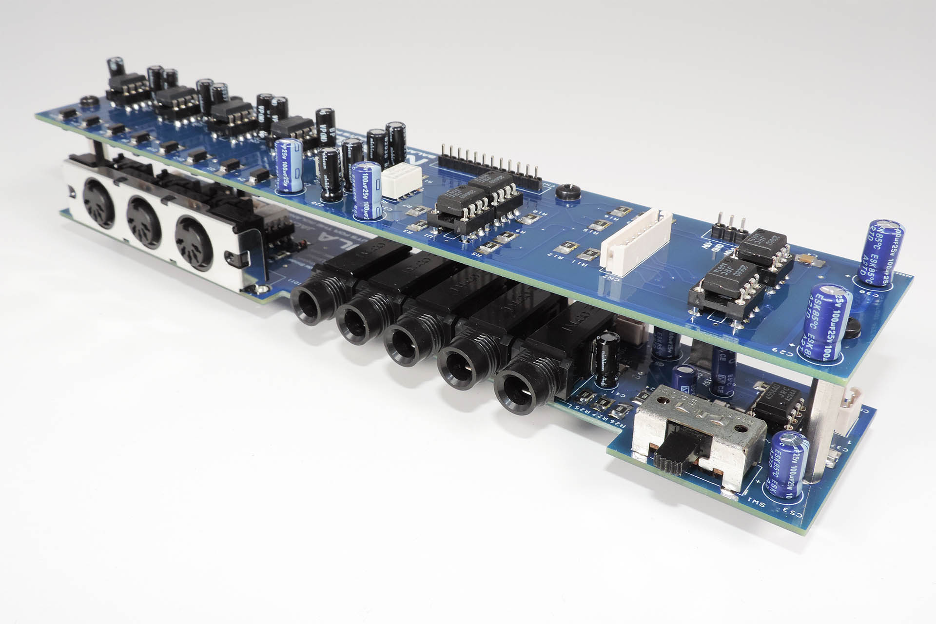
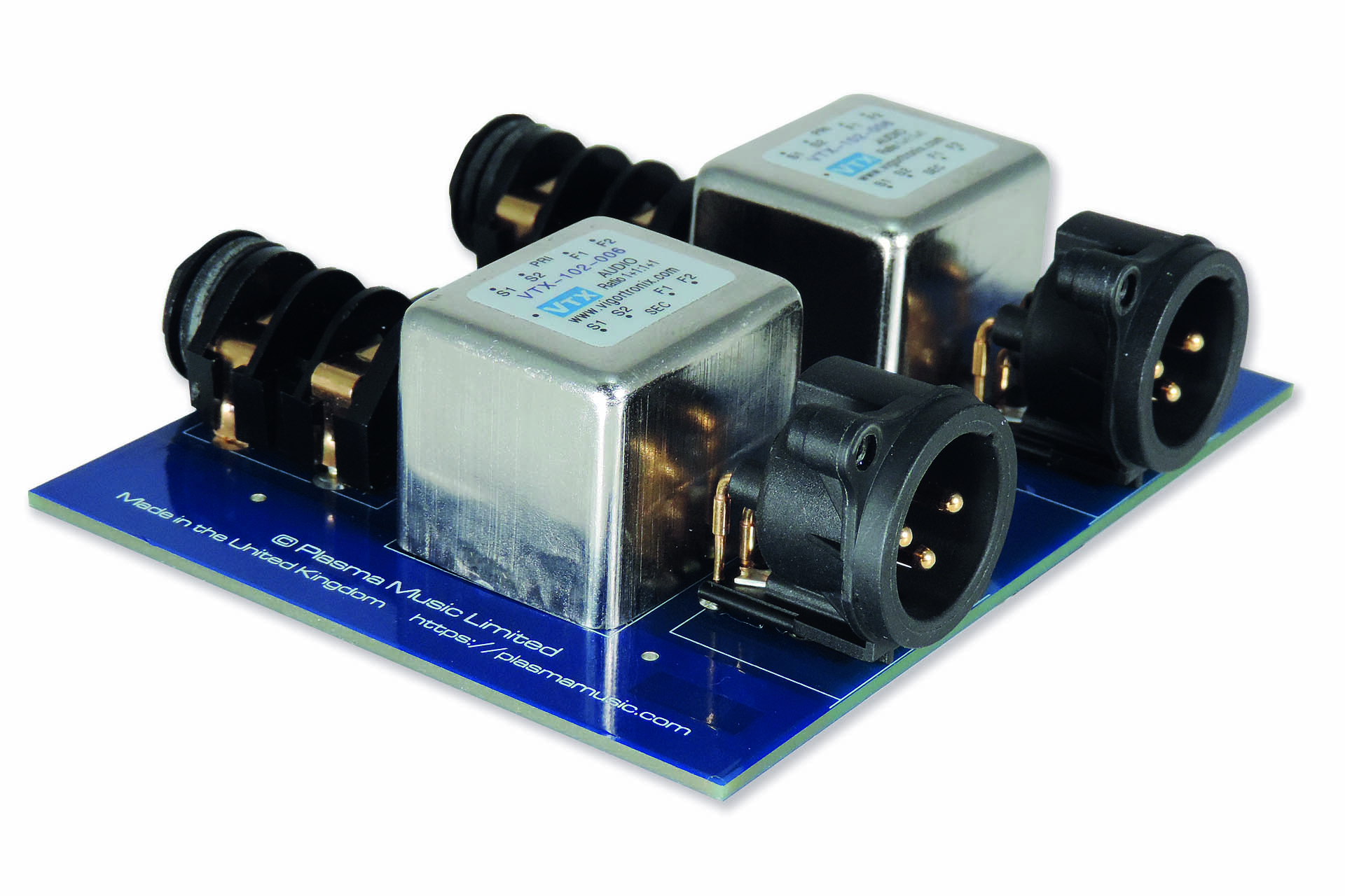
And then there's Nebula. Giving the Roland MKS-70 four high-quality balanced outputs, Nebula also updates the MIDI hardware.
Nebula Balanced Outputs for Roland MKS-70
After receiving many requests from around the world, I even ended up designing rack-ears for this beast!
RE-MKS-70 Replacement Rack Ears Fitted to Roland MKS-70
Currently, I'm working hard on getting my Nebula-X project finished. A version of Nebula, Nebula-X is specifically for the JX-10. With different requirements to Nebula for the MKS-70, Nebula-X has been in the pipeline for a couple of years as I've been forced to take my time over it. Unlike the MKS-70 for example, the JX-10 is a performance instrument and as such, has a whole bunch of pedal inputs, all of which are of course, on the jack-board. Indeed, sourcing some parts to match up with the originals has been a challenge on its own.
Due to the physical layout of the JX-10, noise from the display is picked up by the lines connecting the voice-boards to the jack-board. Nebula-X implements a technology to try to mitigate that noise. As well as having balanced outputs, Nebula-X also has balanced inputs. By replacing the cables in between the voice-boards and Nebula-X with a rewired version of the cable, the Nebula-X system reduces the noise induced from the rest of the JX-10.
Anyway, my Nebula-X project is going well and I hoping to make Nebula-X available early next year.
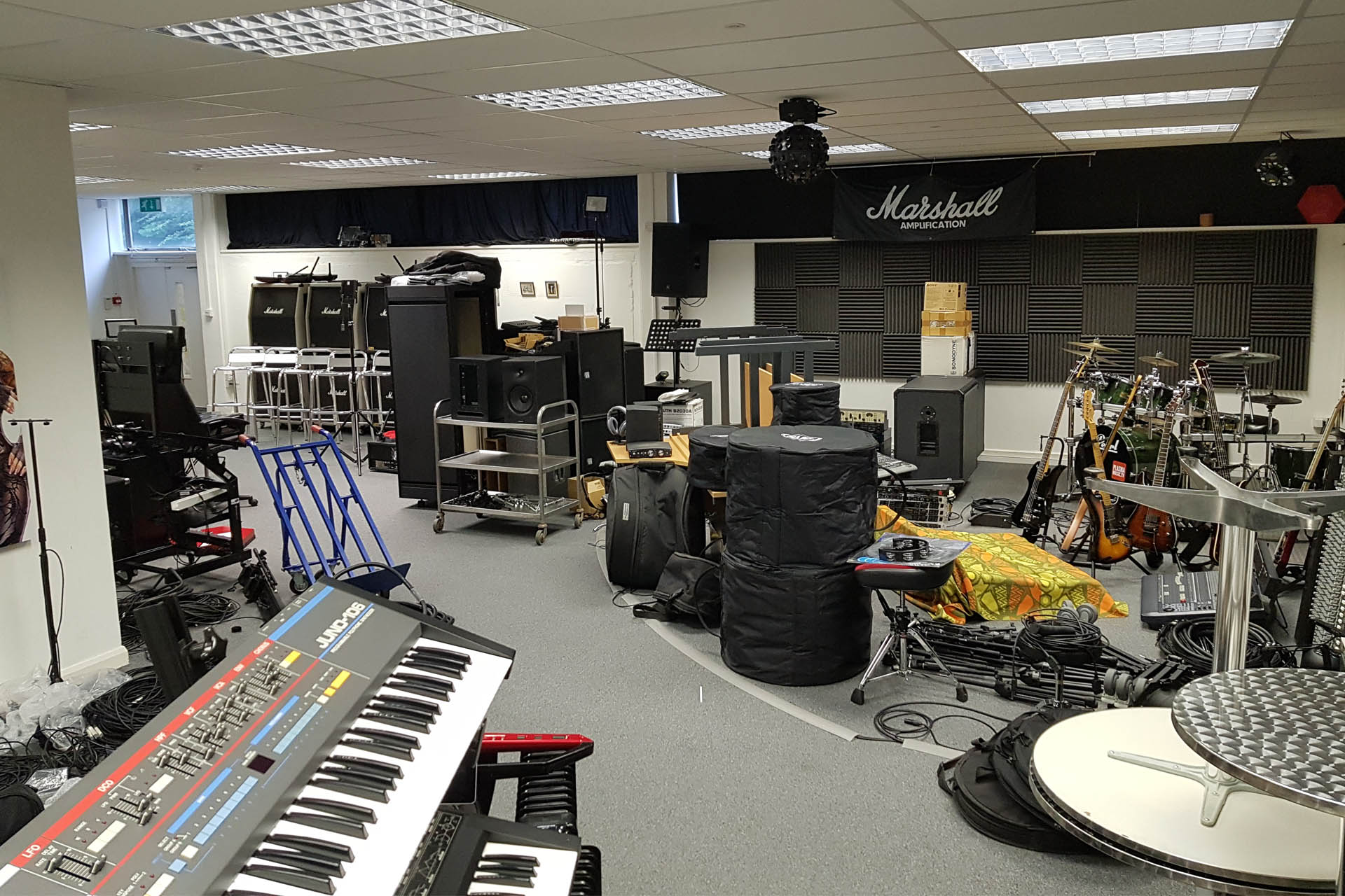
Last year, I started to downsize my recording facility and so a lot of stuff is now up for grabs in my Plasma Music Sale 2020.
It's not just studio gear but drums, cymbals, guitar and keyboard stuff, video cameras, computer equipment and live performance gear like complete PA systems, mixing desks, powered monitors, multi-track recorders, amps, radio mics and so much more.
Some of it's old and some of it is relatively new but either way, it's all been lovingly looked after while I've had it and most of the stuff is in pristine condition and it all works perfectly. Please do check it all out my Plasma Music Sale 2020 here before it all goes on eBay!
If you need more information about a specific item or just not sure about something, then please don't hesitate to contact me.
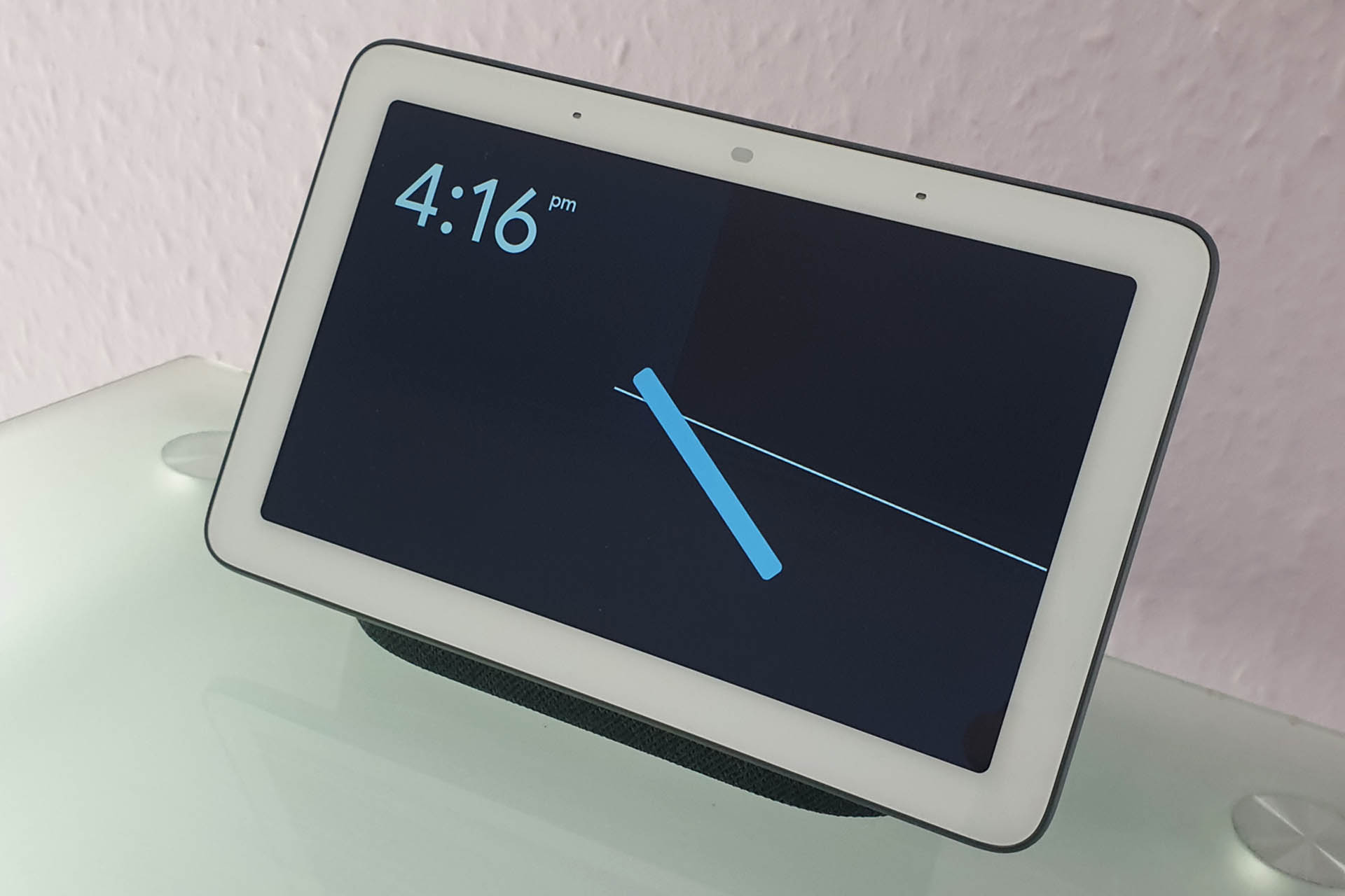
JUST SAY "OK GOOGLE SWITCH ON MY COMPUTER" TO TURN ON YOUR COMPUTER VIA GOOGLE ASSISTANT.
NO MESSING AROUND WITH LOADS OF APPS
NO CUT AND PASTE COMMANDS
JUST SET THIS UP AS A DEVICE IN GOOGLE HOME OR AMAZON ALEXA
Easily installed by anyone with a little technical competence, my Smart Momentary Switch will allow you to switch on your computer, via Google Assistant or Alexa.
My Smart Momentary Switch, or SMS, allows you to switch on your computer via Google Assistant or Alexa, with a simple command like "OK Google, switch on my computer" or "Alexa, switch on my computer".
If your computer is called 'Dave', then telling Google or Alexa to switch on Dave will also work! 😀
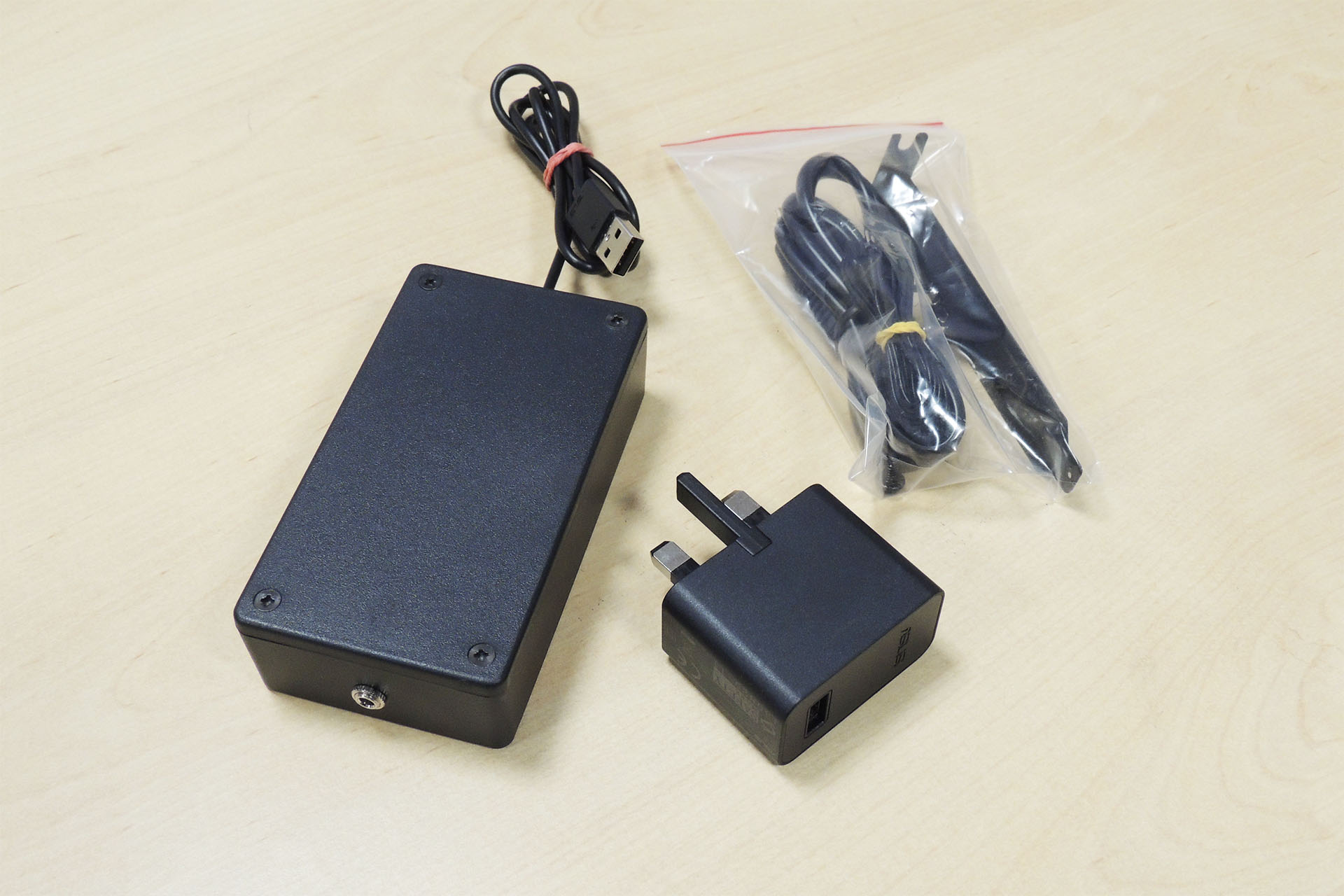
SMS is basically a kit comprising a small plastic box which houses the radio transceiver to connect to your WiFi and a PCI back-plate which fits inside your computer and connects to your computer's motherboard.
The external enclosure is USB powered and a USB power adapter (UK 3-pin) and integral USB cable are included. The box connects to the PCI back-plate via a cable which has 3.5mm jack plugs at both ends.
With easy-to-follow and fully illustrated installation and set-up instructions, SMS can be up and running in minutes.
Please do however, note the follow restrictions:
SMS is ONLY suitable for computers that have an accessible motherboard and a standard motherboard header.
UNFORTUNATELY, SMS IS NOT SUITABLE FOR LAPTOPS, TABLET PCs, STICK PCs AND MACs.
Since parts need to be attached to your computer's motherboard, a basic proficiency of working with computer hardware is required. If you're not confident to open up your computer and move a couple of bits around, then do find a friend who is, to help you.
OK GOOGLE, OPEN MY GARAGE DOOR
Yes, that's right! I make a version of this gadget which can be used to open and close your electric garage door via your Smart Home (Google Home Assistant or Amazon Alexa).
So how much does it cost? 49 GBP plus VAT and postage (almost anywhere). That's a bit more than I'd like but I hand make these myself in small batches. Click here to buy.
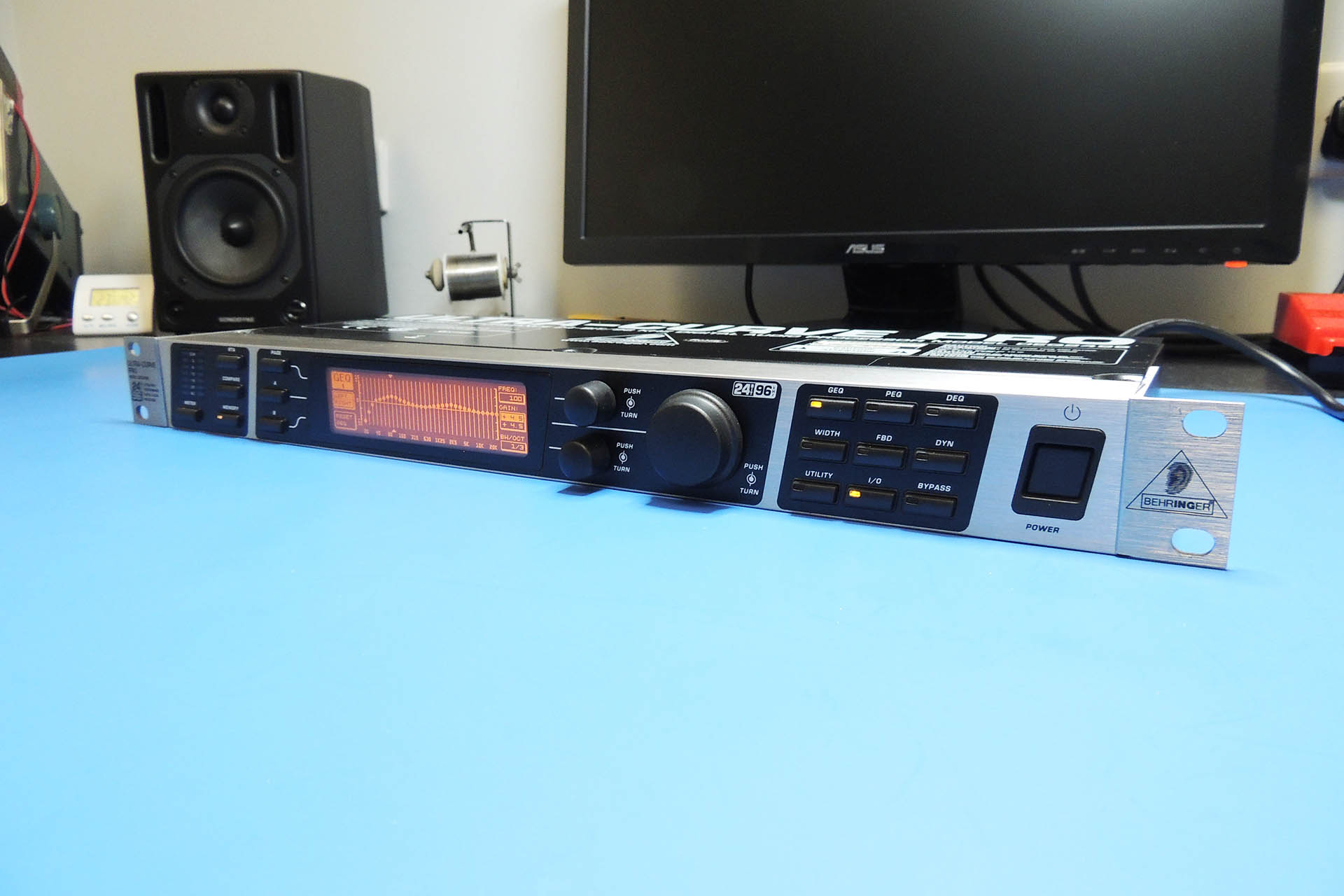
This is the third generation of 'Ultracurve' from the well-known German manufacturer. The DEQ8020 and DEQ8024 were both 2U 19-inch rack-mount units but in 2005, Behringer released the super high-specification DEQ2496... in a 1u enclosure.
These extremely high-quality and versatile processors do a lot more than graphic equalisation. Amongst the machine's function is a real time spectrum analyser. You can purchase a Behringer ECM8000 calibration microphone and quickly and easily set up the graphic to 'compensate' for room acoustics, for example.
There's also a myriad of other functions such as parametric eq, dynamic eq, dynamic processing and time delay, to name but a few.
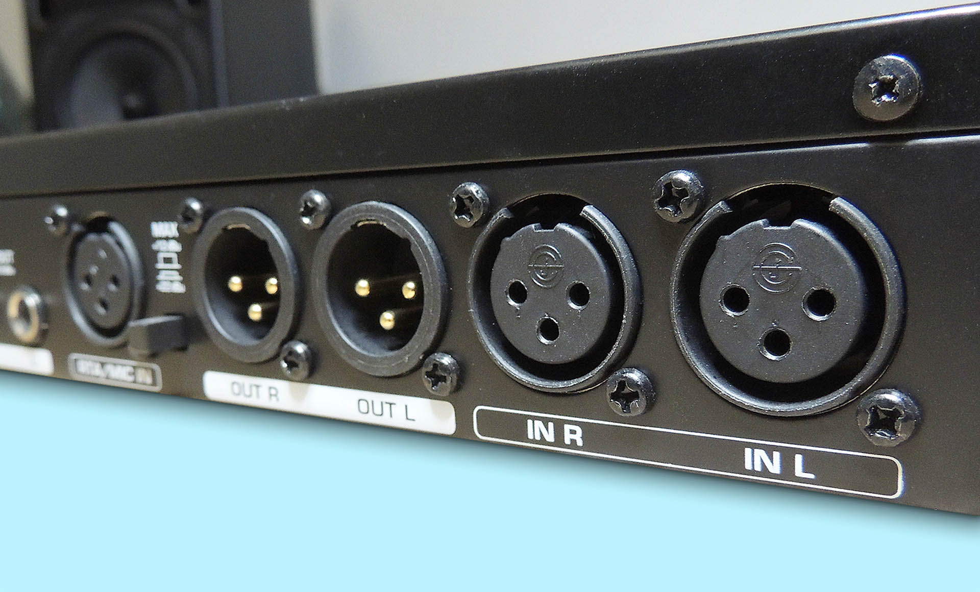
With digital inputs and outputs (S/P DIF on TOSLINK and AES / EBU), the analogue side of the DEQ2496 is balanced and boasts a fantastic dynamic range with its 24-bit / 96 kHz conversion.
Gaining distinction amongst hi-fi enthusiasts and audiophiles, the latest and current Ultracurve is of course, also very popular with theatres, night clubs, PA, recording studios, broadcast and even in musicians' instrument rigs.
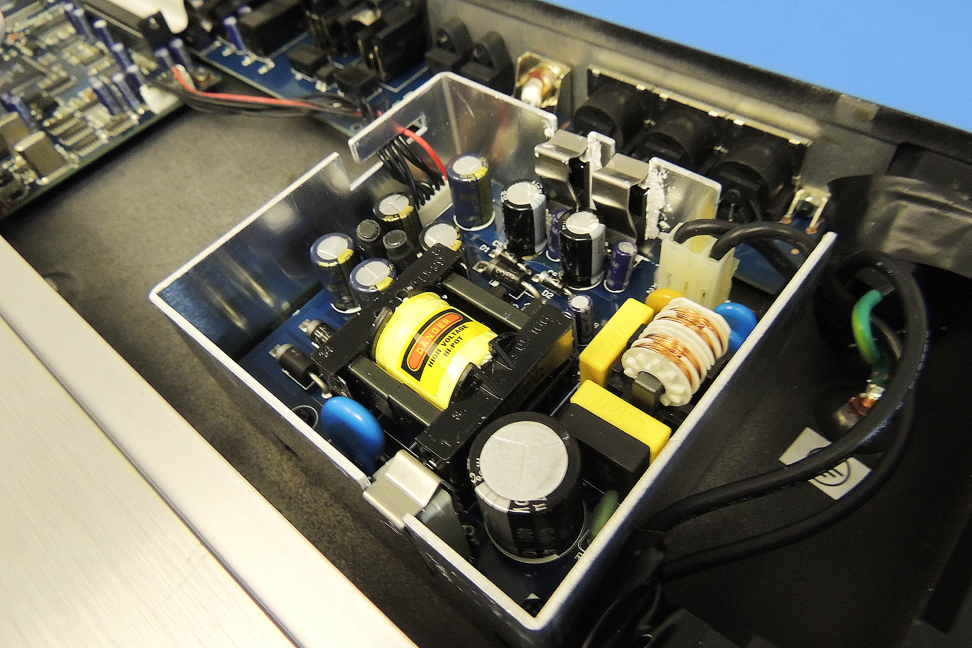
So, unreliable power supply, then? No, definitely not! The date code on the one that's on the bench today is July 2006. That makes it almost fourteen years old and quite honestly, it's done bloody well, in my humble opinion.
The power supply isn't actually a Behringer component but is made by a company called Eton, I believe which has an excellent reputation. Generating so much heat in a 1U enclosure however, takes its toll.
Today's power supply took just over an hour to fix. The parts cost about 20 GBP and in no time, the machine's going to hopefully last for another fourteen years. 🙂
Well, not quite. I got lucky with this one. I've seen a lot of these which have required considerably more fault-diagnostics and that isn't easy on switched-mode power supplies. On top of that, some parts are impossible to get hold of now-a-days. There's not always a magic wand fix for these.
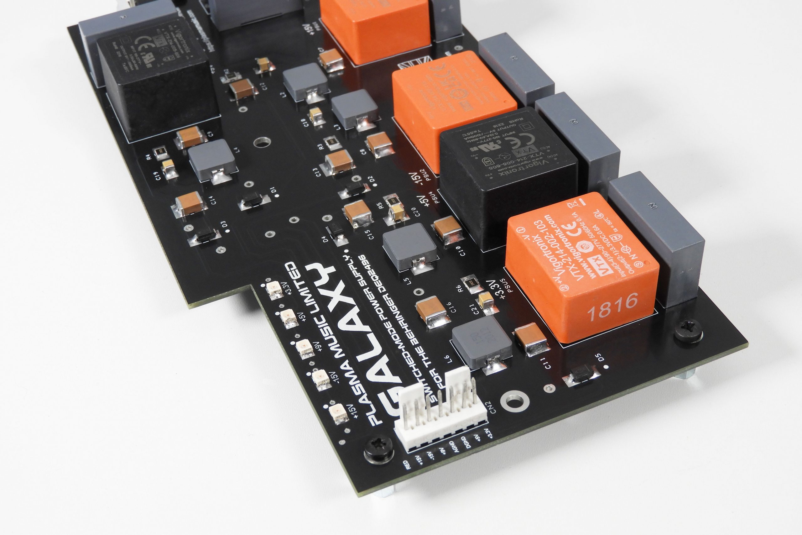
Apart from being my gorgeous wife's birthday, I launched a post featuring my Galaxy project. A replacement power supply for the Behringer DEQ2496 Ultracurve, you can read all about here.
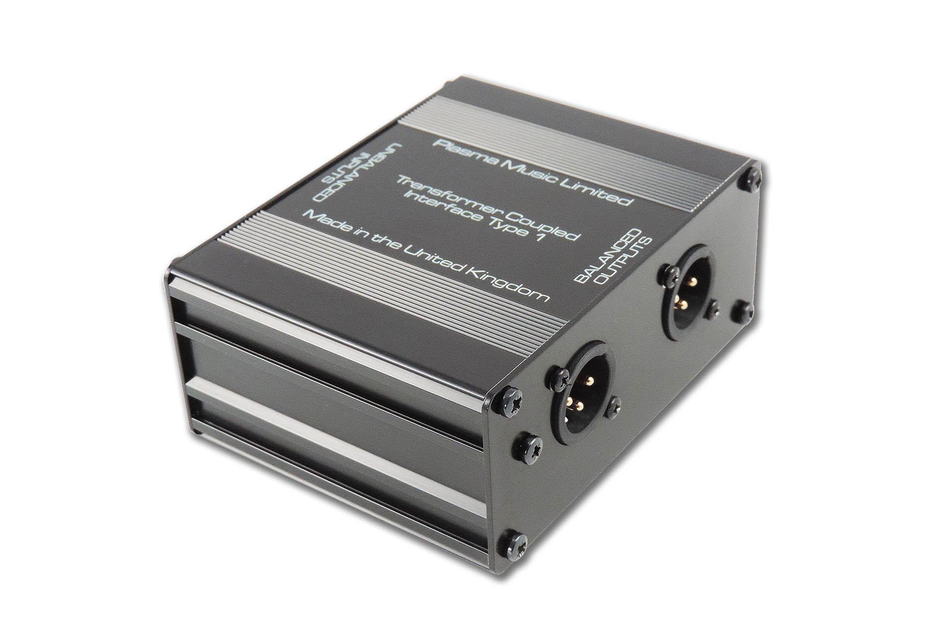
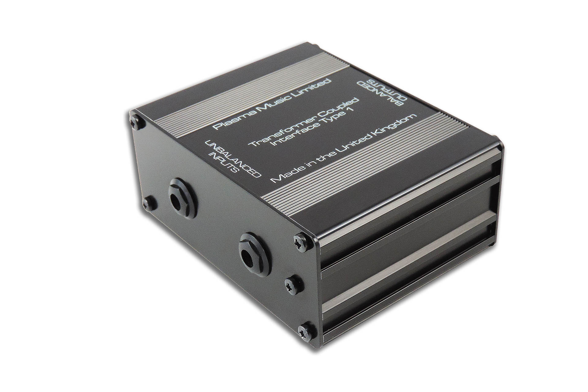
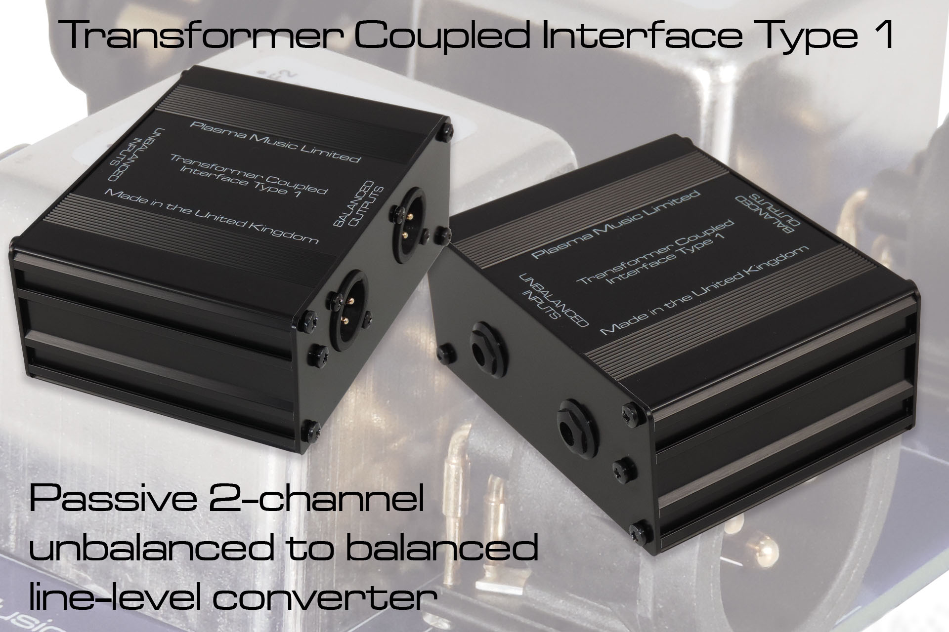
After having made possibly hundreds of these over the years, my Transformer Coupled interface Type 1 is now available to everyone.
Many musicians, engineers and producers appreciate why signals should be kept as 'hot' as possible. High signal levels can reduce your noise floor and of course a lot of professional, studio equipment is designed to run at +4dBu (about 1.25 volts). What many might not appreciate is the virtue of also running balanced signal lines. My unbalanced to balanced converter Transformer Coupled Interface (or TCI) does just that. It converts a +4dBu unbalanced signal to a +4dBu balanced signal (no gain).
SO WHY BOTHER?
So long as the signal level is good, many people would be quite happy to connect an unbalanced output to a balanced input using a cable that connects the pole carrying the 180° out-of-phase signal, to 0V.
Apart from the fact that the balanced version of an otherwise unbalanced signal is 6dB hotter, there’s one big advantage to running balanced signals from your sources to your mixing desk or DAW audio interface and that is, an increased immunity to noise.
Environmental noise exists everywhere all the time. There’s human generated environmental noise such as radio signals, noise generated from switching circuits and so on but there’s also a considerable amount of natural background noise.
To screen signal carrying conductors from noise, cabling comprises a shield which is attached at one end, to the chassis of the source device and at the other, to the chassis of the destination device, thereby ‘extending’ the chassis of each device.
The problem is that screening isn’t 100% effective. We want our cables to be flexible and it’s impossible to achieve a 100% screen, while maintaining a good degree of flexibility.
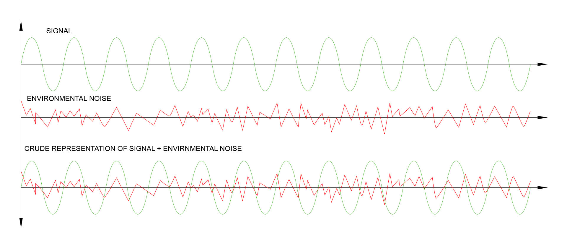
Unbalanced signal is in in green and noise is in red. Unfortunately, noise mixes well with audio signals!
NOTE for all the would-be rocket scientists out there. YES, I'm quite aware that the output waveform doesn't actually look like that but unfortunately packages like Adobe Illustrator aren't able to display a Fourier combination of what they see as a pair of vector traces. That's why I've blatantly written 'CRUDE REPRESENTATION'. In addition, I personally think this representation makes it easier to 'see' what's going on, particularly for the uninitiated.
So where were we? Ah, yes...
Another approach is that of the balanced line…
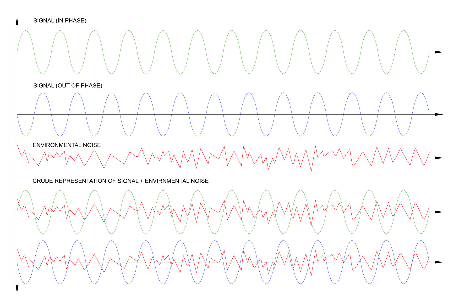
Instead of sending a single signal, we send two signals; one being a copy but 180° out-of-phase with the first and then at the receiving end, we put things back to a single in-phase signal.
Noise is in-phase, everywhere. Nothing is producing a 180° out-of-phase load of noise, right? This means that noise is affecting both the in-phase and out-of-phase signals in exactly the same way.
With me so far? Good.
At our receiving end, the (differential) input stage rejects all signals that appear the same on both the in-phase and out-of-phase lines, this being… noise and ‘passes’ everything that is 180° out-of-phase… our signal.
Similar to the previous figure but the out-of-phase signal is in blue. Now, take a closer look at the last pair of waveforms and you'll notice that noise (in red) is in-phase on both signal lines. When fed into a differential amplifier, all common phase signals such as this noise, are 'filtered' out or rejected .
So how cool is that?
I get asked this a lot but after reading all of that, I hope you now understand that balancing the outputs of your equipment will NOT get rid of noise generated by your equipment. It’ll only reduce the effects of noise between your source and destination devices.
A figure known as the Common Mode Rejection Ratio (or CMRR) is the measurement in decibels, of how much signal that's common to both phases is filtered out by a device.
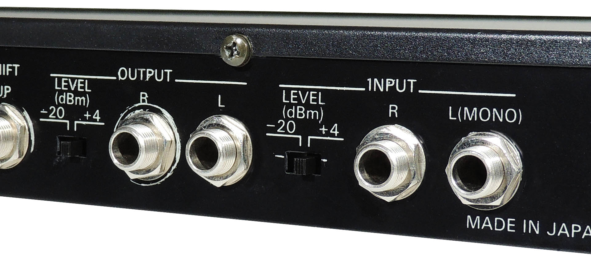
Anyway... unfortunately there's a lot of older gear out there including stuff we all love dearly, which has unbalanced +4dBu outputs. The Marshall JMP-1 that was featured in a recent post, is a prime example. The Roland RSP-550, an excellent nineties multi-effects processor, is another example.
Unbalanced but switchable -20dBm/+4dBm inputs and outputs on an old Roland RSP-550
So, the traditional way to convert an unbalanced signal to a balanced signal is to run it into a D.I. box. We're all familiar with those little boxes that cover many a studio and stage floor, right? They work just great but while they balance the signal, they also knock down the level of the signal to a few millivolts which means that you have no option other than to run the other end into a mic. pre-amp, either as a separate unit or built into a desk. That's not always convenient and it seems stupid attenuating a signal, only to amplify it again, anyway!
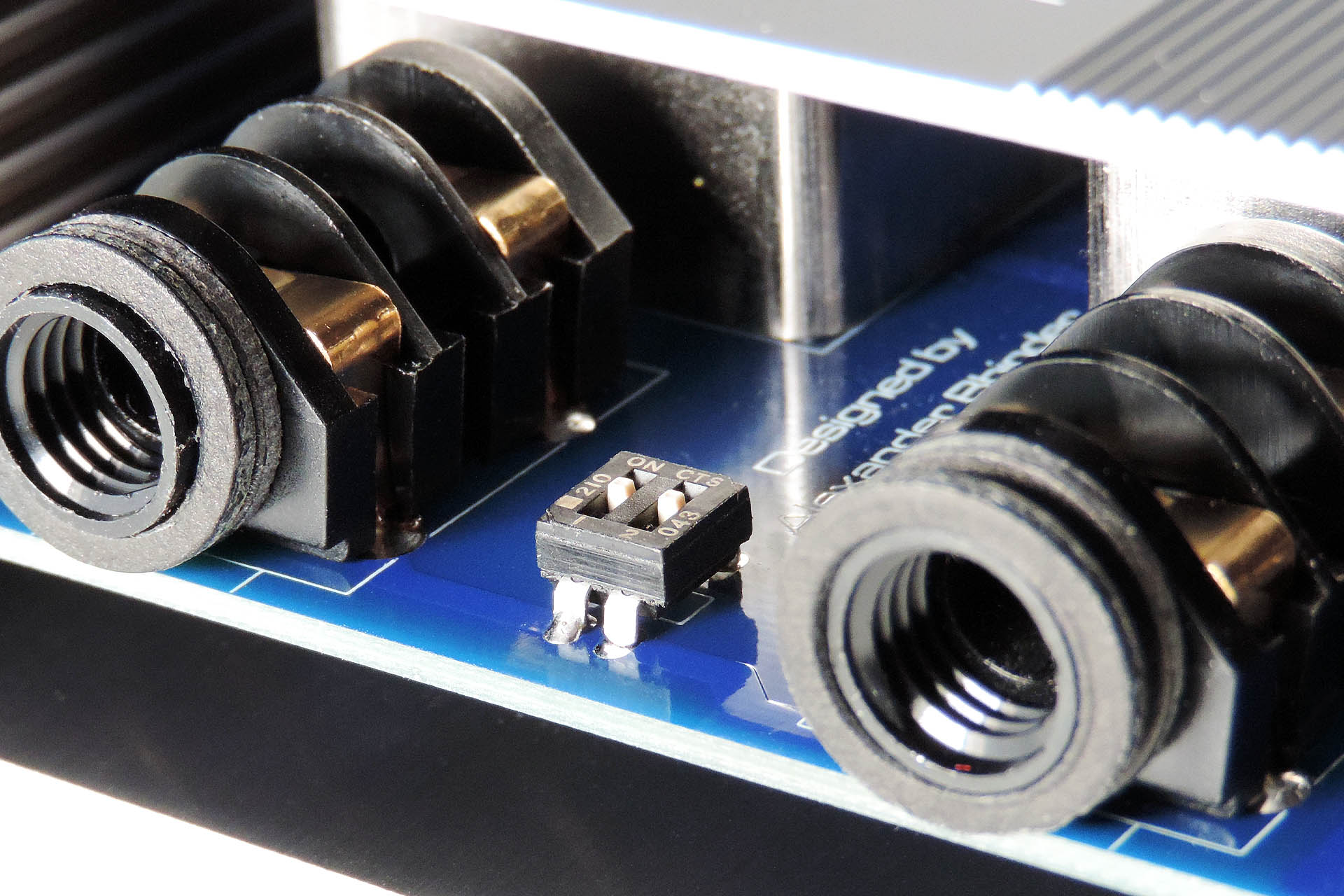
The inputs on the TCI Type 1 are conventional 2-pole 6.35mm jack sockets.
Have you noticed another downside to trying to use a D.I. box to solve this problem, yet? Earlier I gave the example of the Roland RSP-550. It's an effects unit. It has +4dBm outputs sure but it also has +4dBm inputs! So sending a signal from your desk to it via a D.I. box isn't going to work! The inputs on the RSP-550 are looking for either -20dBm or +4dBm. The microphone level output from a D.I. box just won't be enough to drive the unit. On top of that, the D.I. box output is balanced. The inputs on the RSP-550 are unbalanced. That's actually two downsides. 🙁
To convert an unbalanced signal to a balanced signal and maintain the level of the original signal was a problem I decided to solve once and for all, many years ago. I developed the transformer coupled interface (TCI) Type 1. It's not rocket science (as they say) but boy, do these things come in handy.
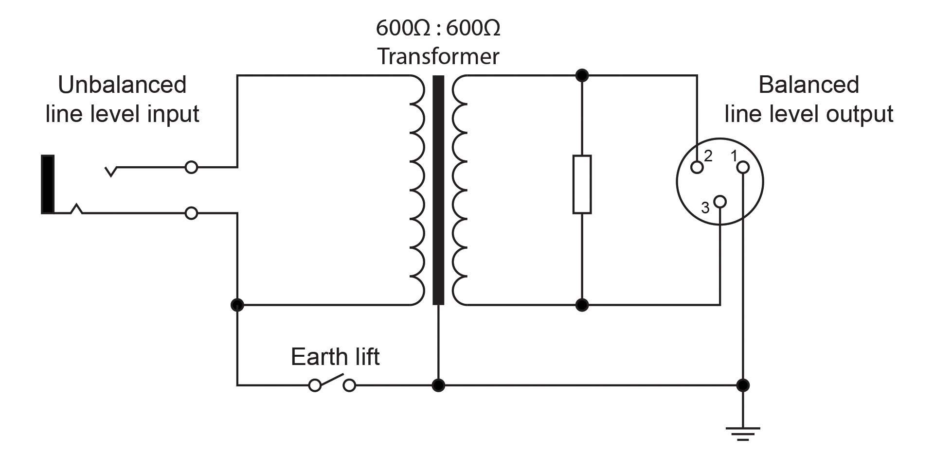
Here's a basic representation of what's inside my TCI unbalanced to balanced converters (single channel shown).
The TCI is a non-powered device (like a passive D.I. box) which basically comprises a single transformer on each channel. For an unbalanced to balanced converter, that's kind of all you need, really.
For those interested, the resistor shown, is reflected in parallel with the winding on the side of the transformer facing the unbalanced input (on the left). It helps maintain a consistent input load as presented to the output of the (unbalanced) source.
Having said that, you of course, want the highest quality transformer you can get. You need a good frequency response but also, good phase coherency. Phase distortion, especially down the bottom end, is characteristic of cheaper transformers and if not addressed, makes bass guitar for example, sound woolly or flabby.
Similar to a passive D.I. box, one hidden benefit to using the TCI, is that it offers something called galvanic isolation which means that there is no physical connection (like a piece of wire for example), between your source and destination equipment. With the ability to easily lift the earth of the source equipment, the TCI Type 1 is just great for helping to get rid of ground loop problems!
The TCI is equipped with separate earth-lift switches on each channel, thereby offering full galvanic isolation which can help eliminate ground loop hum.
Returning to the RSP-550 and similar effects units that have line-level but unbalanced inputs, for a minute, driving an unbalanced input from a balanced source isn't such a big deal. Shorting the out-of-phase signal to ground will be fine for this although I might consider releasing a TCI Type 2 one day. 🙂
IMPEDANCE
All equipment has what’s called an input impedance and an output impedance. Impedance, like resistance is measured in Ohms but differs in that it's frequency dependant. Impedance varies with frequency and so the impedance at say 500Hz will be different to the impedance at 5kHz. Having said that, due to the nature of things, a common resistor is often used on for example, the output of an electronic circuit to provide the output impedance of a system.
Most guitarists will be quite aware that everything to do with guitar electronics is high impedance and that the first thing you plug your guitar into should have a very high input impedance. This reduces the ‘loading’ on the guitar pick-ups and allows for a good frequency response further on down the chain.
Unbalanced outputs like those found on a lot of consumer electronics such as hi-fi gear, have a high impedance, perhaps in the order of thousands of Ohms. Balanced outputs in contrast, are always low impedance; just a couple of hundred Ohms. Again, I won't go into the physics suffice to say that this is why amongst other things, low impedance outputs allow for long cable runs.
There are exceptions however and while unbalanced, a lot of studio gear has low impedance outputs. This makes life a lot easier!
The TCI is classed as a low input impedance device and while it will technically work on something with a high output impedance, you might notice some high-end roll-off. Basically, you’ll need to check the output impedance of your gear before considering a solution like the transformer coupled interface. That’s why D.I. boxes are so popular. D.I. boxes have a high input impedance which means you can plug in just about anything. Like my transformer coupled interface, passive D.I. boxes also have a transformer to convert the input to a balanced line. The turns ratio of the transformer however, is such that while presenting a high impedance at the input and low impedance at the output, the signal voltage is greatly attenuated. Hence, the output of D.I boxes is mic. level.
The outputs on my favourite MIDI valve guitar pre-amp, the Marshall JMP-1 can be switched to +4dBu but... they're still unbalanced. Grrr...
The TCI Type 1 is housed in a fully screened aluminium enclosure. On top of that, TCI's transformers are individually contained in MU-metal cans. This combination all contributes to a very high level of noise immunity.
TCI Type 1 is a double screened device considerably improving noise rejection.
Here are the specifications of my TCI Type 1:
NUMBER OF CHANNELS
2
FREQUENCY RESPONSE
30Hz – 30kHz
INPUT IMPEDANCE
6.4kΩ - 6.5kΩ
OUTPUT IMPEDANCE
<600Ω
INPUT CONNECTIONS
2 x ¼” (6.35mm) 2-pole jack socket
OUTPUT CONNECTIONS
2 x 3-pin male XLR socket (pin 2 is in-phase)
DIMENSIONS
(L) 80mm x (W) 80mm x (H) 47mm inc. feet
WEIGHT
<350g
My TCI Type I unbalanced to balanced converter, is an amazing little problem solver and is now available to buy here...
The TCI Type I is enclosed in a fully screen aluminium box, tastefully black anodised and well, if you don't like feet, please turn away now!
UPDATE - 13th August 2021
Out of the first sixteen TCIs sold, thirteen went to audiophiles, something I really didn’t expect but which I can relate to.
Of course, now-a-days, many powered hi-fi speaker systems, have balanced inputs, especially sub-bass speakers and headphone amps. You’ll be hard pushed however, to find a high-end pre-amp with balanced outputs. Luckily, most have low output impedances and offer very high signal levels, making them ideal for connecting to the balanced inputs of powered speakers, via a passive unbalanced to balanced converter like the TCI Type 1.
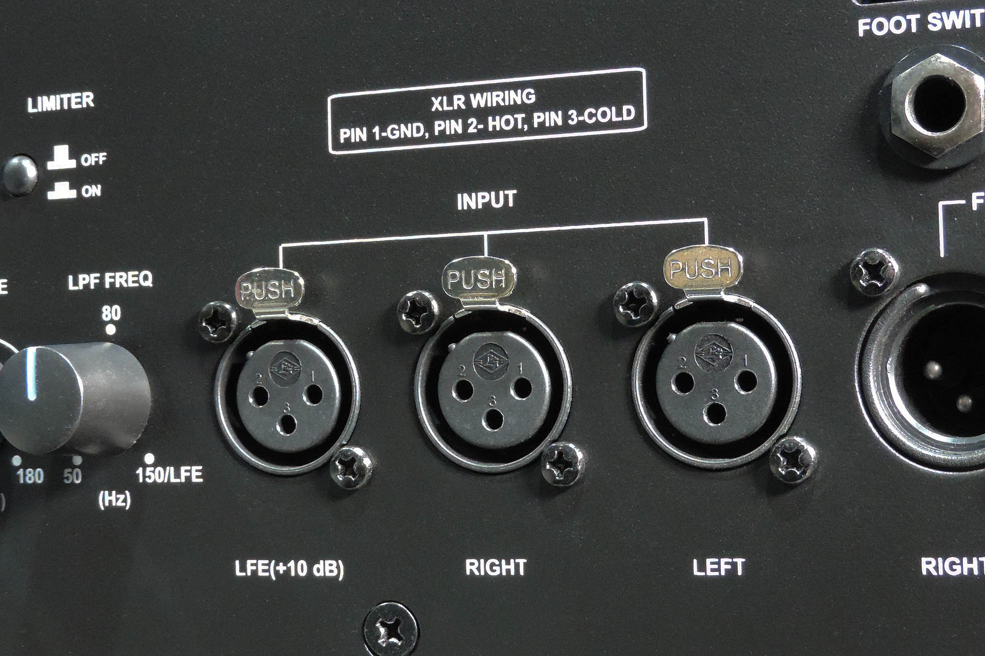
The rear of this Sonodyne SLF-350 sub-bass system only has balanced inputs.
TCI Type 1 was designed for studio applications and so has ¼” jack input sockets and not RCA phono sockets, normally found on hi-fi equipment. Short RCA phono to ¼” jack cables are however, easily available and if you really get stuck, I’d be more than happy to make a pair.
The outputs of one customer's pre-amp were on 4-way DIN sockets and again, please just contact me if you need custom cables made.
UPDATE - 31st March 2025
I'm very proud to probably have the best customers in the world! Every once in a while though, I get an email which just makes me feel like what I do is so worthwhile. BUT...
Then I get an email which is truly humbling.
This evening I received an email from a customer who bought a TCI Type 1.
"Hi Alexander,
I have got the TCI today.
Thank you very much, the sound is perfect.
I made the music video on YouTube. You can check the sound quality and your device in video. Also I wrote about Plasma Music in description of video."
After 3:28 minutes in the video below, you can see the TCI Type 1 that my customer is using. The stunning sound you're hearing is passing through it. No... don't listen to this through your phone. Play it back on something proper!!!!
I had no idea of the situation in which my little TCI Type 1 was going to be used but definitely didn't imagine that it would be interfacing the likes of DAC and Concert Fidelity equipment. How incredibly amazing to see my TCI Type 1 amongst such giants. How incredibly humbling and how lovely of my customer to get back to me and let me know.
Like all my stuff, TCI is designed and made by me, here in Hemel Hempstead, UK. I do however, use sub-contractors for making enclosures, PCBs, etc. Unlike many, I only use local companies and here's why...
I'm deeply concerned about the environment and the exploitation of labour and so I always use local manufacturers in preference to the Far East, with the following in mind:
I can be confident that workers are treated fairly and earn a proper wage.
I can be confident of the standard of quality of each item that is delivered to me.
Communication is important and using local manufacturers, all correspondence is quick and understandable.
I believe in supporting the local economy.
I can be confident that the disposal of manufacturing waste is managed properly and in accordance with national and EU law.
Using local manufacturers isn’t the cheapest option but the above points are important to me. I hope that they’re important to you too.
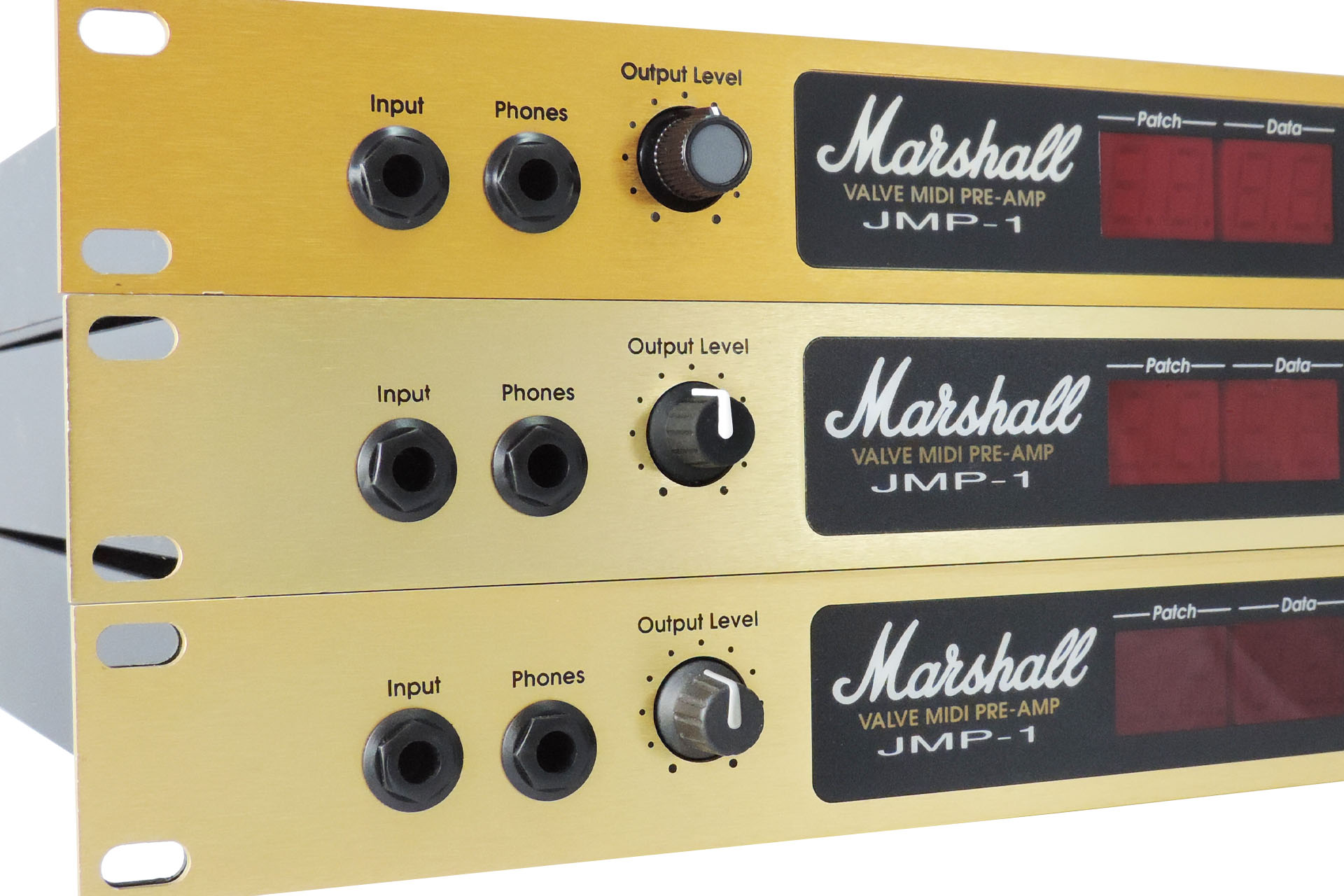
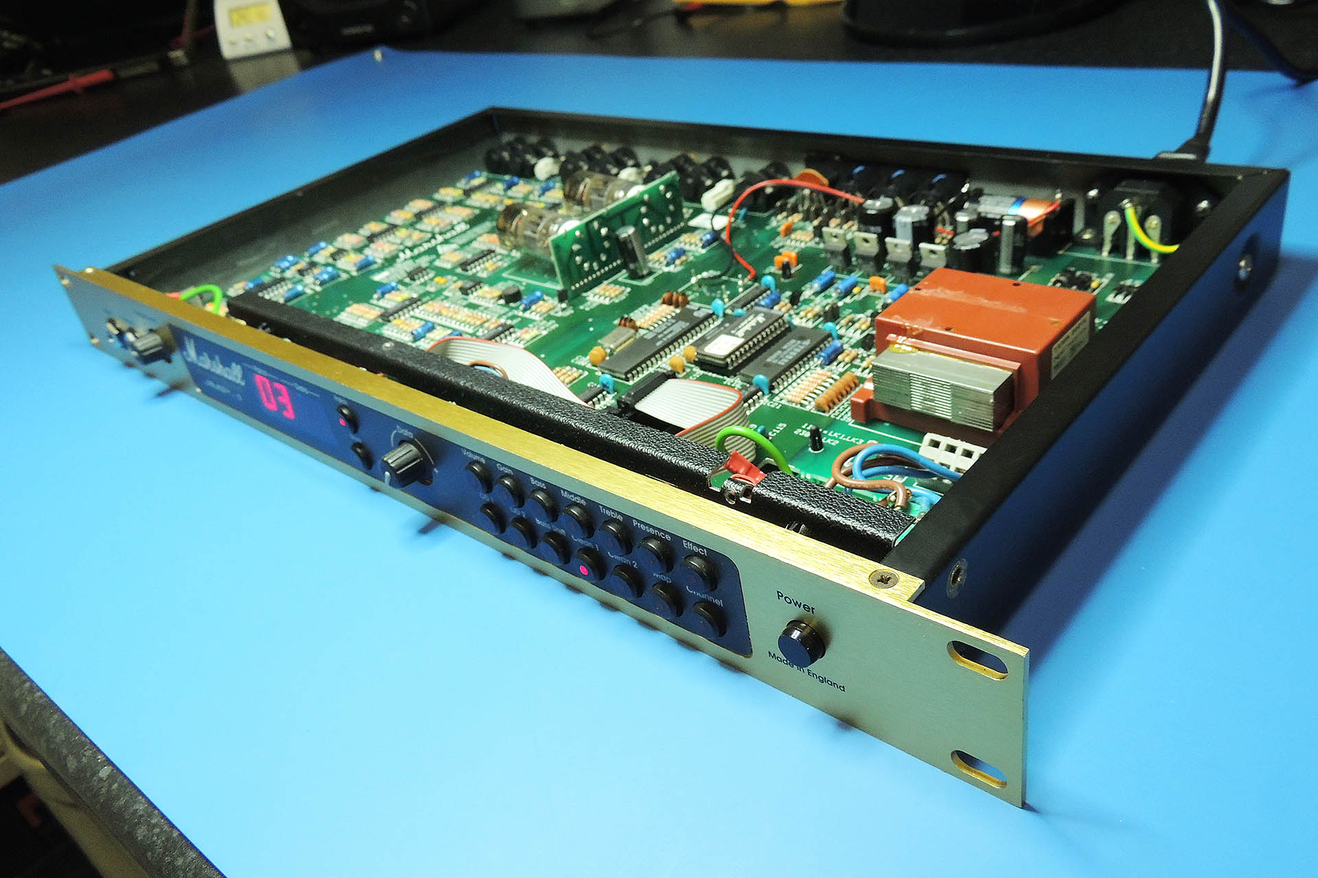
Here’s a Marshall JMP-1 MIDI valve pre-amp that I’ve just serviced.
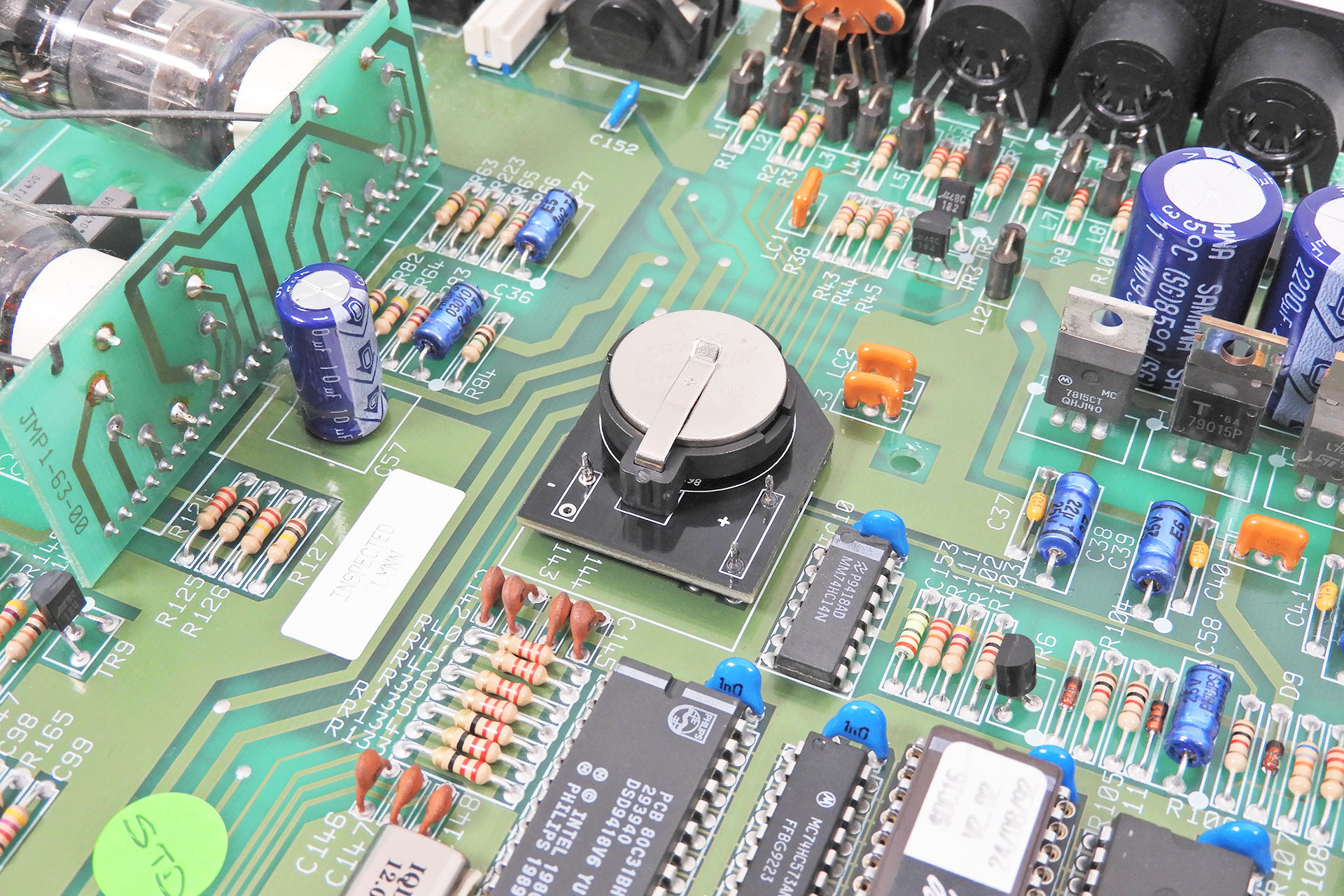
I’ve changed the valves and power supply capacitors, cleaned up the metal work and implemented my ‘Live-Forever’ battery mod’. The original battery is mounted bang in the middle of the main PCB, so you really don't want this to leak.
The serial number indicates that it was built in early 1992 which not only makes it twenty-eight years old but one of the first JMP-1s off the Marshall production line.
An early MIDI valve pre-amp although following the likes of similar pre-amps like the ADA MP-1, the Marshall JMP-1 has always been a really under rated bit of kit, despite the fact that named artists such as Billy Gibbons (ZZ Top), Phil Collen (Def Leppard), Iron Maiden, Megadeth and many more, still use them even today. In production for well over ten years, also says something about this little gem.
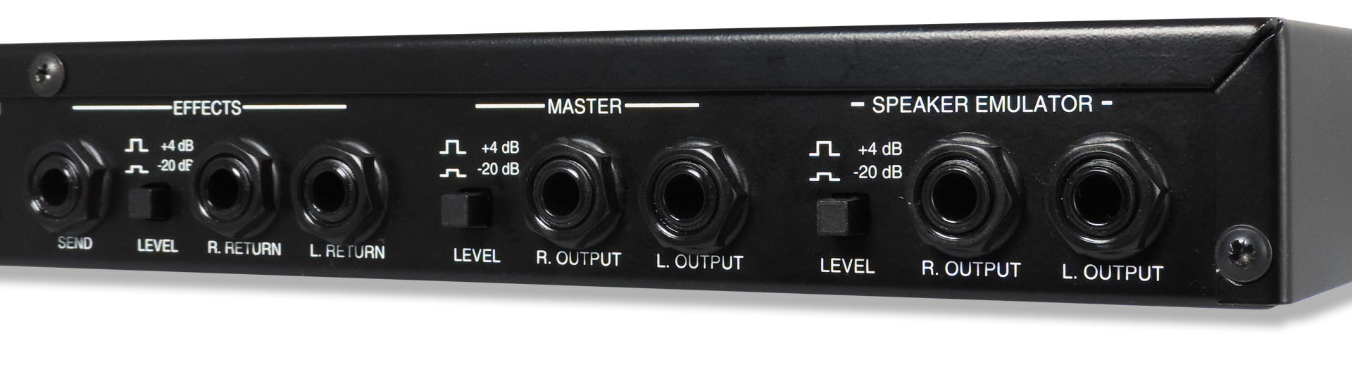
The JMP-1 is not a modeler like modern stuff; it’s the real thing, just with MIDI. Run into a valve power amp (or two), it just sounds amazing and the quality of the speaker emulated outputs is definitely good enough to go straight into the board or your DAW.
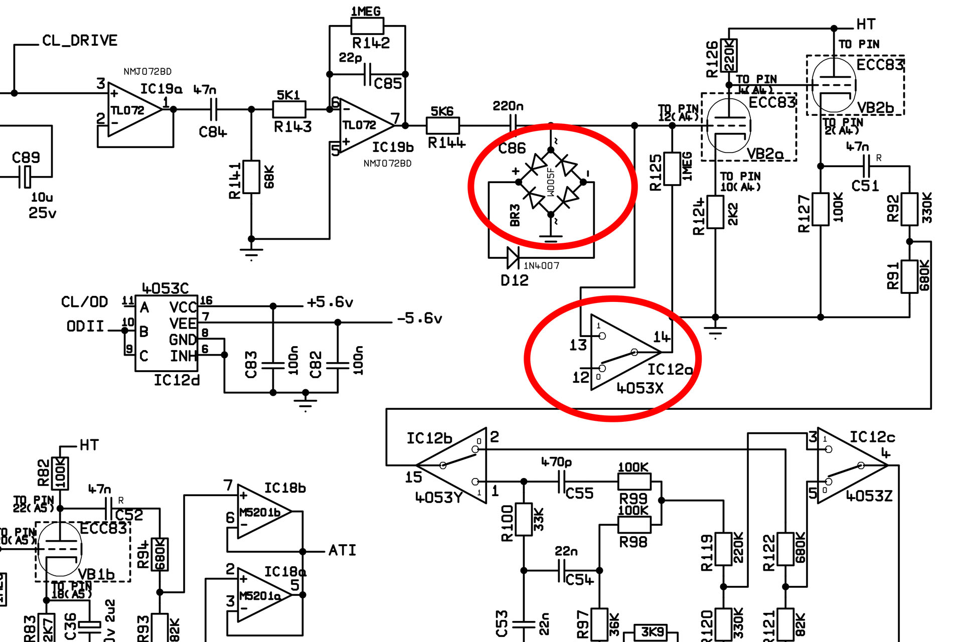
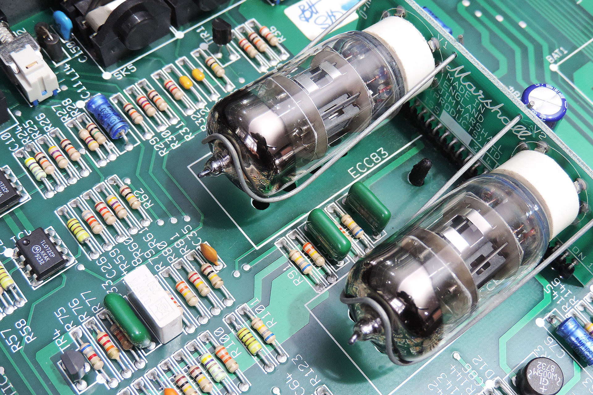
With most of the distortion being generated in the semi-conductor domain (some of which is highlighted in the image below), many purists might shy away from this beast.
On the other hand, classic Marshalls such as the legendary Silver Jubilee series and the monstrous JCM900 Dual Reverb, also use semiconductors to produce some of their distortion tones.
And then there's the clean channel of the JMP-1 which is based on the classic Fender design... with a few tweaks, of course. Anyway, at the end of the day, it's the sound that counts and as I've said, these things have still got it, even today.
RATTLE A' HUM
Lots of JMP-1s hum. This doesn't come through the audio outputs but it can be annoying and I've been trying to get to the bottom the cause for years.
Now, instead of looking at the JMP-1, I'm going to look at what the JMP-1 is plugged into…
We all know that mains voltage is AC (alternating current). The voltage varies between 100V and 240V depending on where you are in the world. The frequency also varies and can be either 50Hz or 60Hz. We convert this AC voltage to DC (direct current) to power appliances, gadgets and other systems that now dominate our lives. So why is the supply AC and not DC, then? Well, the answer to that is a little involved as there isn’t a single reason. Predominantly however, it’s a matter of safety. If you are in contact with a mains supply (eek), the alternating nature and the frequency of the supply gives the human body enough time to react and pull away. There are other reasons to do with energy but safety is the main reason that the electricity supply is AC.
Unfortunately, it’s not pure AC, though. There’s a DC element present in the mains which has actually grown over the past twenty years or so due to the fact that the number of appliances that use what’s known as half-wave rectification has increased. I won’t go into just why half-wave rectification dumps DC on the mains suffice to say that it can be an issue for some devices.
“So how does that affect my Marshall JMP-1?” I hear you ask.
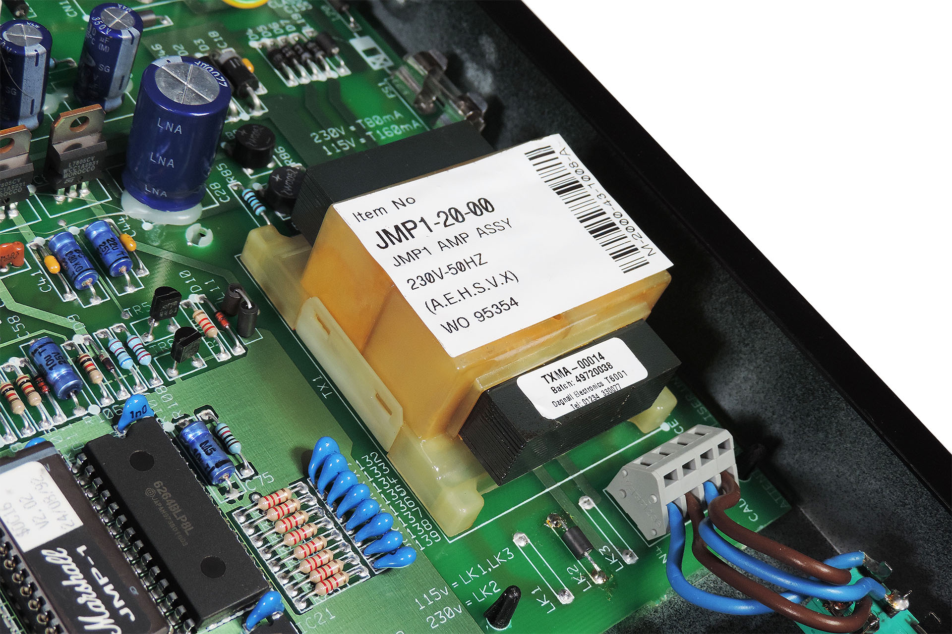
Well, the other downer is that some appliances contain components that are particularly sensitive to the DC offset on the mains supply and it just so happens that the transformer in the Marshall JMP-1 is one of them. 🙁
Anyone with a little electrical know-how will now wonder how that can be. Transformers are inductive components and so filter out DC. Yep, that’s absolutely correct and in fact the DC that’s on the mains doesn’t get through to the rest of the power supply in the JMP-1.
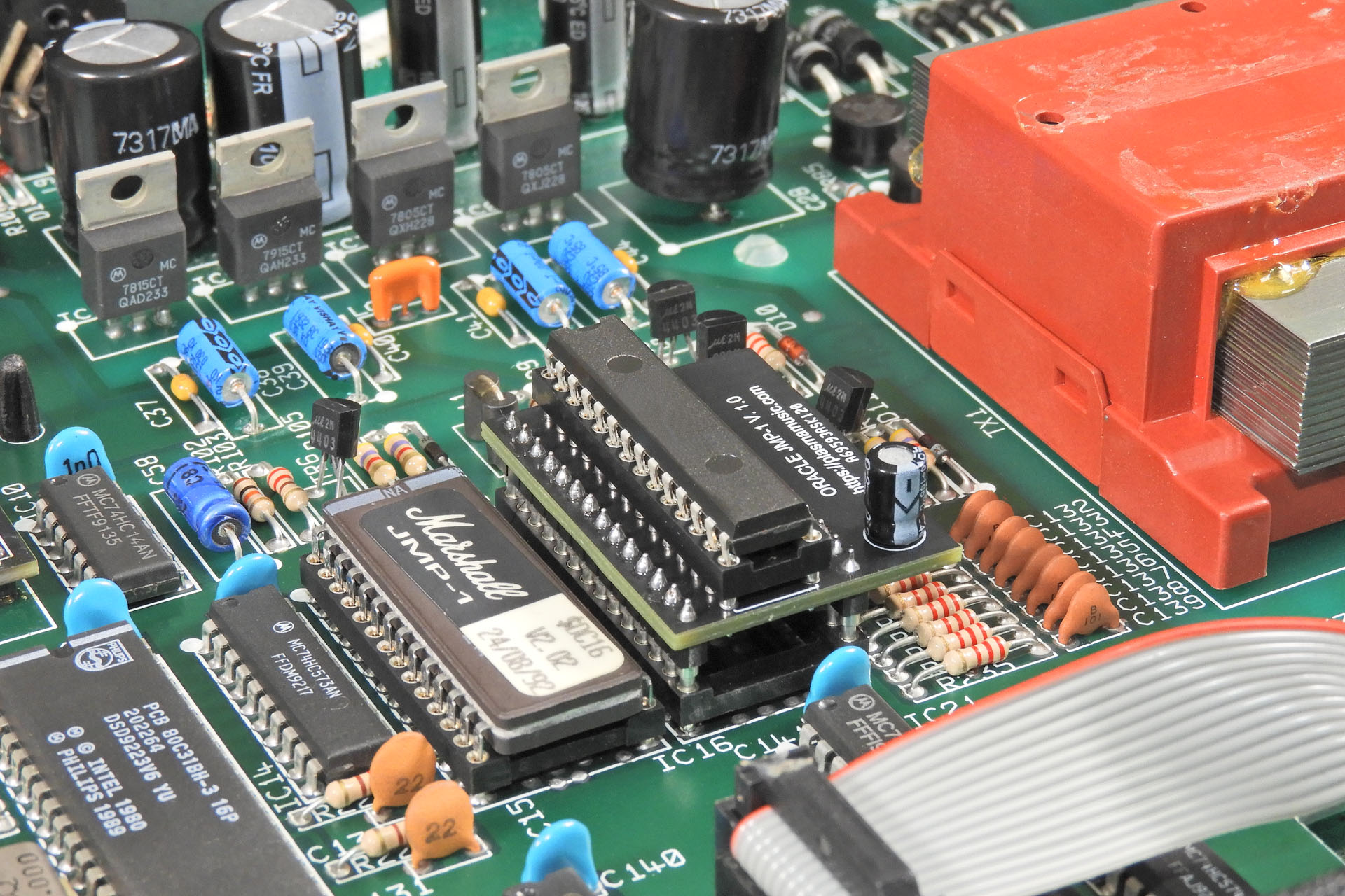
What the DC component can do however, is saturate the core of the transformer, thus causing the laminates to oscillate. The gap between the top of the transformer and the inside of the JMP-1's top case is very small so you can guess what happens. That's why the hum disappears when you remove the top-case!
The core of the transformer in the JMP-1 saturates due to the presence of DC on the mains supply.
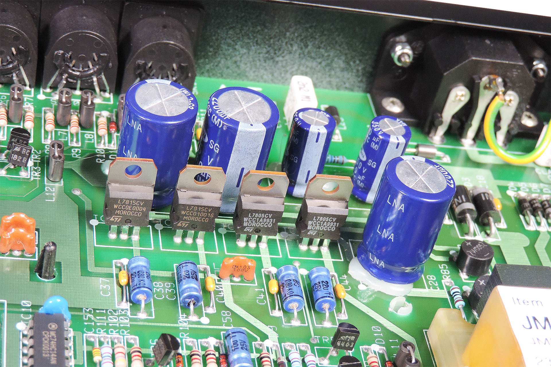
What pointed me in this direction was that after being on for about an hour or so, the laminates on the transformer get seriously hot. I mean SERIOUSLY hot. The JMP-1’s regulators however, don't. In fact, they don’t even have any additional heatsinking. This paradox was intriguing. I concluded that the transformer heats up as a result of oscillation. As mentioned, the heat is substantial and the transformer is heavily stressed as a result. Over time, this will reduce the life of the transformer. I'm afraid it's just a matter of time before the transformer fails. 🙁
The regulators in the JMP-1 don't have any additional heatsinking because they don't run hot.
I should mention the obvious; the JMP-1 has got a couple of valves in it! Although running at about 300V, much higher voltage than the semiconductor parts of the analogue circuitry, they consume very little current and hence, the supply for the valves isn’t regulated. The valve heaters run at about 6.3V and although they ‘heat’ (obviously), it’s not normal to regulate the supply to the heaters, either.
It's very unusual to regulate the voltages to pre-amp valves.
Familiar with DC offset on mains being a problem on high-end audiophile equipment, all the evidence seemed to be mounting up. 🙁
You can suppress the hum with cushioning between the top of the transformer and the case but this will only keep the transformer from dissipating heat that's generated as a result of the problem and hey, it doesn't actually fix things, does it?
If asymmetrical voltage supply is indeed the problem, then the only real and proper solution is to get rid of the DC component all together.
I'm pretty determined to get to the rout cause of this and will keep everyone posted on how my pursuit for the quiet Marshall JMP-1 progresses.
UPDATE - 4th January 2021
If you want to read more, my latest Marshall JMP-1 post is here. I now provide replacement Marshall JMP-1 Knobs Nuts and Bezels sets which you can read about here.
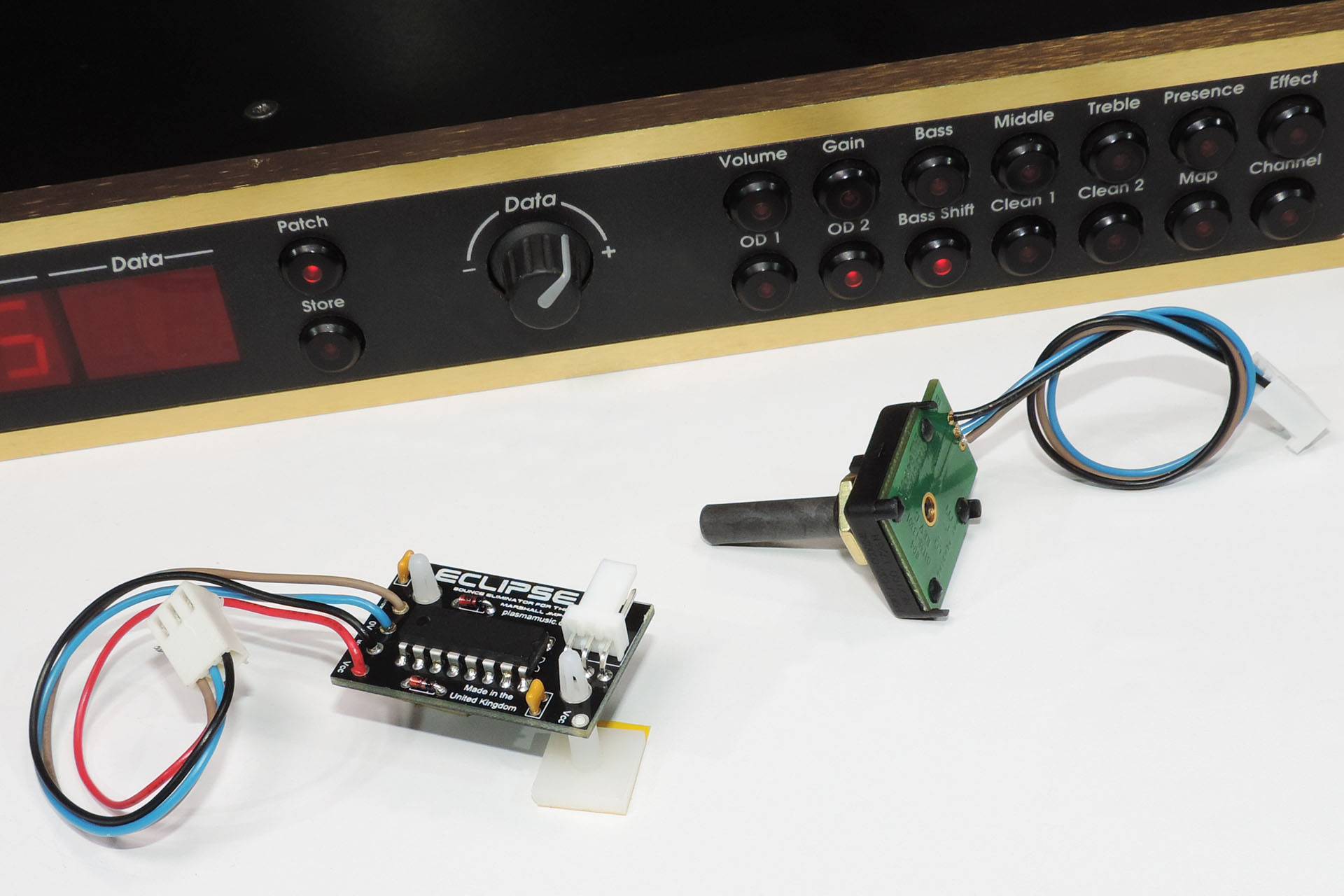
I've also developed something called Eclipse; a bounce eliminator which can be fitted by anyone with a little technical know-how and which gets rid of the data entry knob skipping thing! You can read about Eclipse here.
Eclipse bounce eliminator for the Marshall JMP-1 stops data entry knob skipping once and for all.
UPDATE - 13th March 2021
A thousand apologies, Plasma People! What with the flood back in August and COVID-19, I've been a bit distracted! 🙁
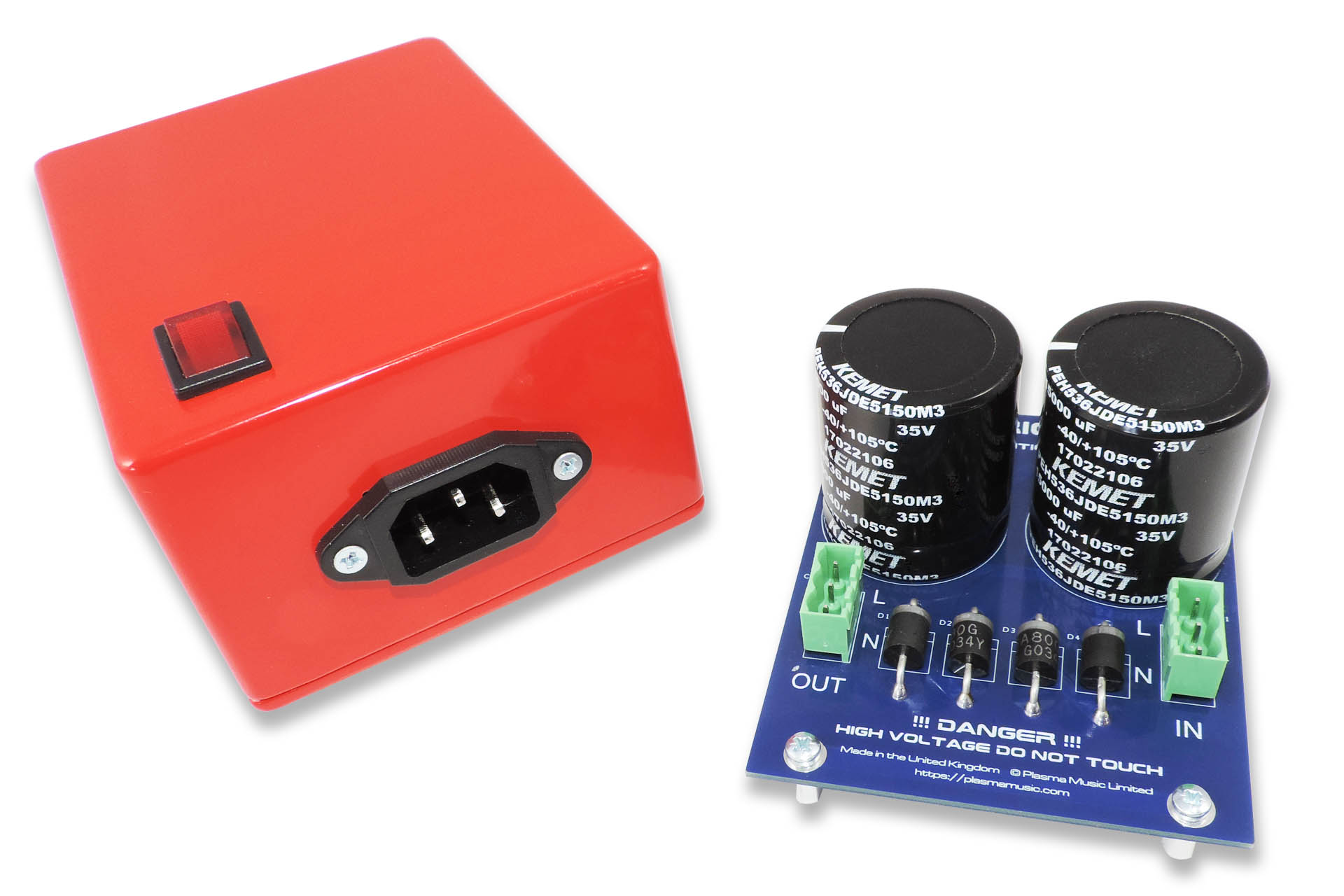
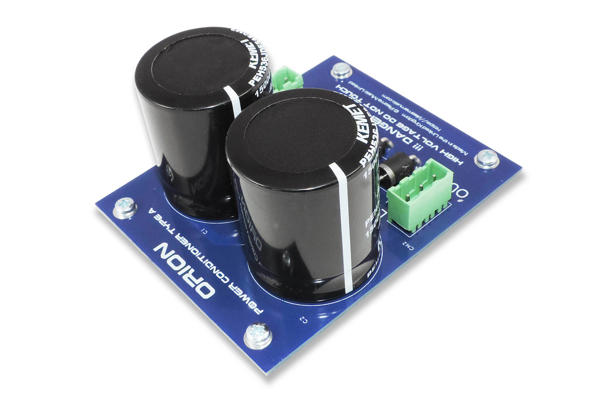
Anyway, on the back of my theory that the transformer in the Marshall JMP-1 may be susceptible to mains DC off-set, I designed Orion Type A, a DC filter / blocker.
Orion worked very well and indeed does filter out DC on the mains but... I'm afraid it didn't get rid of the hum on the JMP-1.
This is what's inside my Orion Type A DC filter. It works great but doesn't do anything for JMP-1 transformer hum. My theory wasn't sound.
THERE'S STILL LIGHT AT THE END OF THE TUNNEL
A few months ago, I managed to track down a chap called Graham Sopp. Graham has a company, the name of which may be familiar to some. It's called Dagnall Electronics. The reason for potential familiarity is that many of you will recognise it as being that on the side (or top) of many a Marshall transformer! That includes our beloved JMP-1's power transformer.
Well, Graham wasn't just exceedingly knowledgeable but was also very (VERY) helpful. We had some considerable correspondence over e-mails and he expressed his surprise at my theory of DC off-set being the reason behind our humming JMP-1 transformer, suffice to say his scepticism was well founded.
Anyway, Graham's suggested that I conduct a few tests and get back to him with my findings. He said there are two potential paths to follow; the first is that I return humming transformers which will have their laminations replaced and will then be re-varnished. The second is that 'we' design a new transformer using a higher specification material for the laminates.
Dagnall Electronics is a design company and does not manufacture anything. The company that actually makes the transformers, is called TRX Electronics and is based in Malta. TRX Electronics is no longer set up to manufacturer the TXMA-00014, the original JMP-1 transformer. This means that developing a TXMA-00014 Mk II (?) could be quite expensive, if TRX Electronics even considers taking on the job. On the other hand, it would be quite impactable for JMP-1 users, me and TRX Electronics, to send potentially single transformers back and forth.
As I said, I really am on a mission to resolve this but please be patient. Drop in here every once in a while and I'll get back to you as soon as...
UPDATE - 22nd June 2021
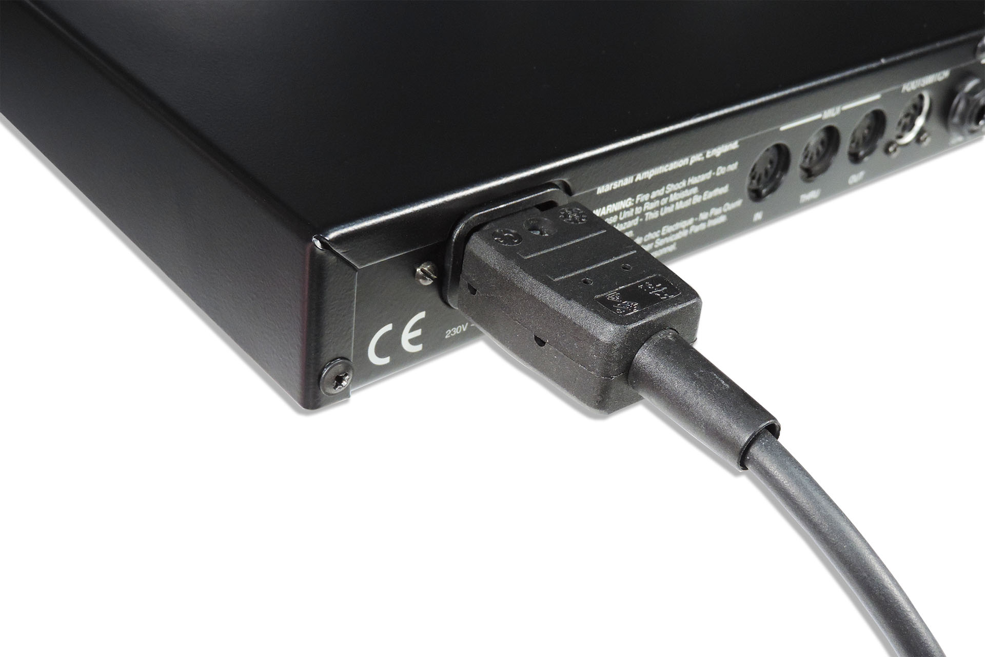
While the outputs of the Marshall JMP-1 are +4dBm line-level, they're also unbalanced, which was quite a common feature (or lack of) for the time. I spent quite a while, looking to install balanced output drivers into the JMP-1 but changing the 2-pole sockets over to 3-pole, was a major obstacle for my plans .
Today however, I released my Transformer Coupled Interface (TCI) Type 1 which is a passive stereo unbalanced to balanced line-level converter. TCI allows you to properly interface your favourite MIDI valve guitar pre-amp with your DAW or mixing desk. You'll notice the difference! 🙂
At last; balanced line outputs from your JMP-1.
You can read all about my TCI Type 1, here or you can check it out in my on-line store, here.
UPDATE - 21st September 2021
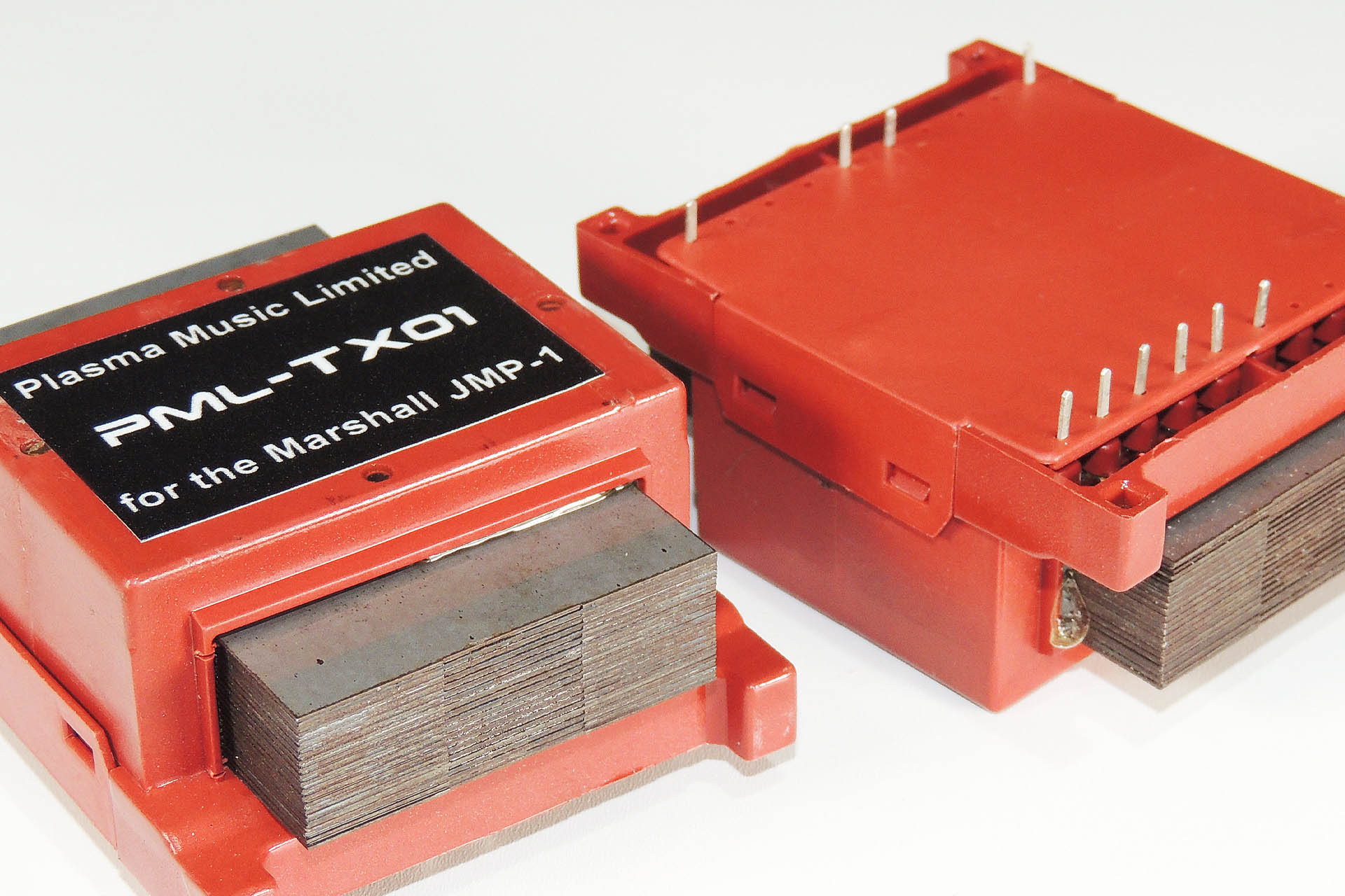
At last!!!! 😀 My PML-TX01 upgraded replacement transformer for the Marshall JMP-1 is finally here!
And here it is... my PML-TX01 transformer for the Marshall JMP-1.
The laminates of the PML-TX01 are made from a higher specification material, thereby reducing hum and hence, heat generation, too.
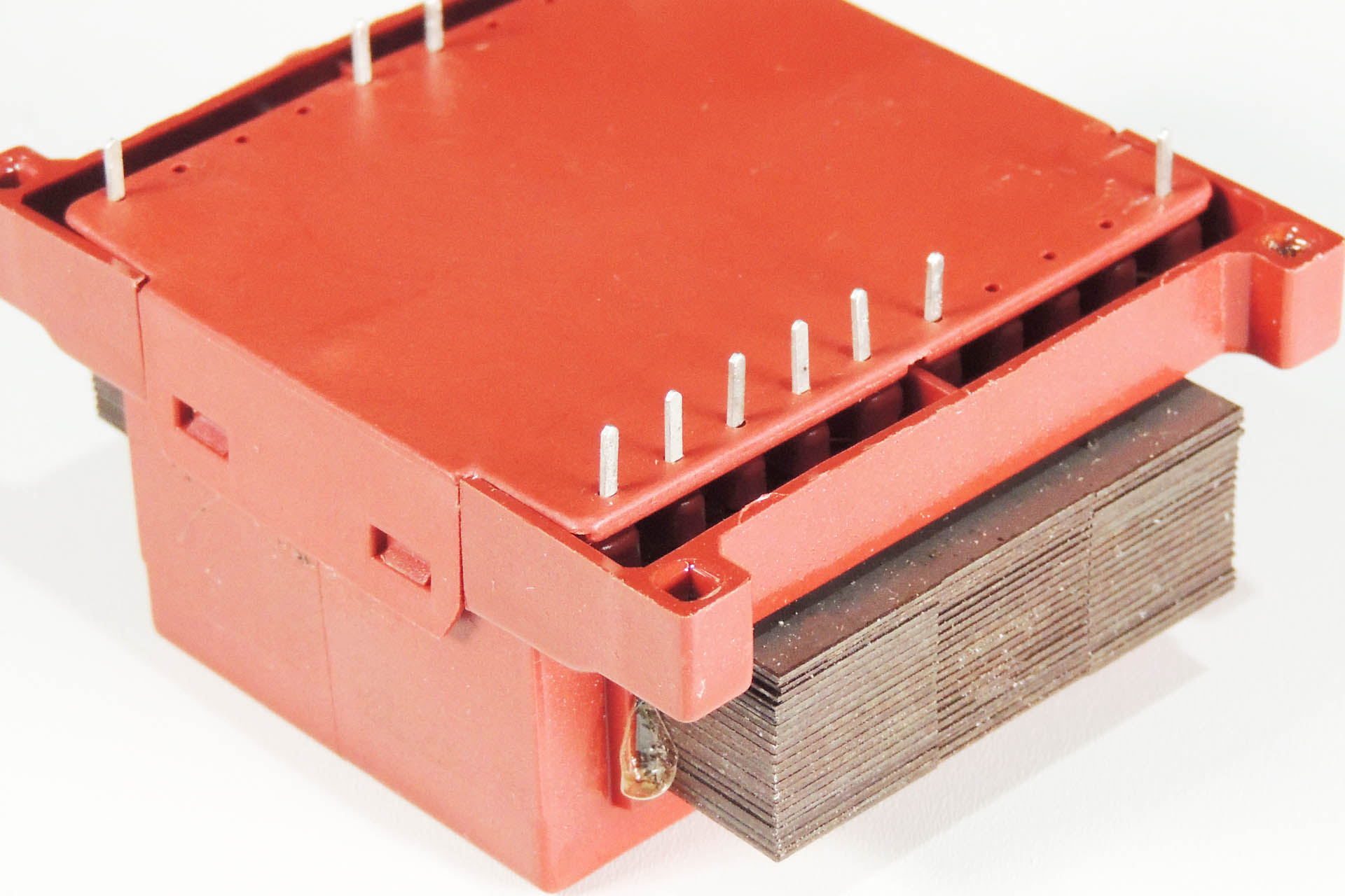
Exactly the same size and pin-for-pin compatible with the original TXMA-00014, my PML-TX01 is a true drop-in replacement.
My PM-TX01 is of course pin-for-pin compatible with the original Marshall TXMA-00014
You can buy my PML-TX01 here:
This item regularly goes out of stock, I'm afraid but... I encourage customers to back-order. Unfortunately, the crappy e-commerce plug-in I use, only tells the links (like the one above) that the item is out of stock. What 's the bloody point of that?!?!?! So if you want this, then please just visit the PML-TX01 page on my e-store here. Grr...
Marshall JMP-1s now go for between £400 and £700 (yes, £700). If you can pick one up nearer £400, then I personally think you've got yourself a bargain and a seriously good bit of gear.
If you want to find out more about the JMP-1, then there's loads of resources on-line and of course there are Marshall JMP-1 groups on Facebook like this one: https://www.facebook.com/themarshalljmp1
I know this box inside-out and I absolutely love it and love working on them, so if you have a JMP-1 that's in need of a little TLC, then don't hesitate to contact me.
UPDATE - 22nd July 2023
I often get asked about the memory back-up battery in the Marshall JMP-1 and with soldered batteries not really being in fashion anymore, replacements are difficult to get hold of. I therefore decided to knock up a small PCB that mounts into the original battery location but which has a CR2032 clip. This allows for easy battery changing with a standard (you guessed it) CR2032. Measuring the voltage on the battery is a little easier, too. 🙂
UPDATE - 26th February 2024
Now available in my on-line store, a screw kit for the Marshall JMP-1.
UPDATE - 10th April 2024
My latest upgrade for our favourite MIDI valve pre-amp is Oracle JMP-1 battery eliminator for the Marshall JMP-1. You can read all about it here.
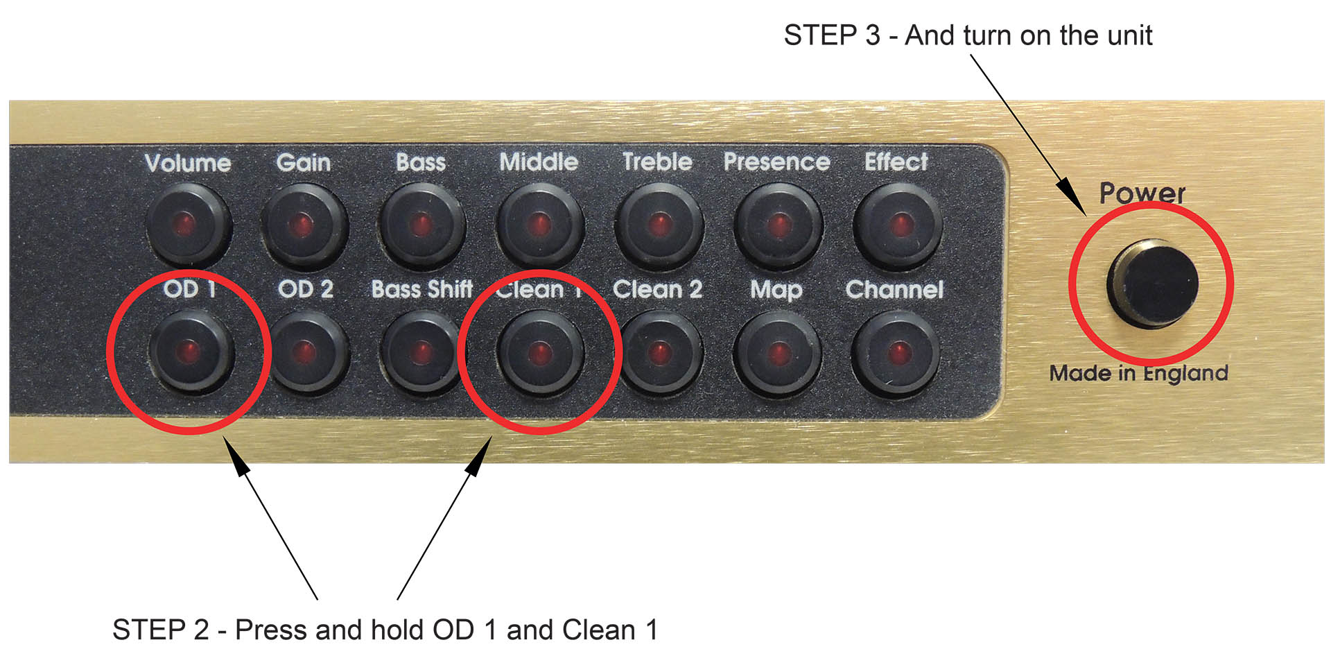
MARSHALL JMP-1 FACTORY RESET
WARNING: Implementing this procedure will permanently delete all user-made changes to any patches. If you want to save your JMP-1's memory, do a MIDI dump first.
Switch off JMP-1 via the power button on the far right.
Hold down the <OD 1> button and the <Clean 1> button.
While holding down these buttons, switch on the JMP-1.
Wait a few seconds while the display flashes and then release the OD 1 and Clean 1 buttons.
Now then, you're JMP-1 might NOT reset! Yes, that's right. If your machine is locked, performing a factory reset will be useless until you unprotect your JMP-1’s memory.
To check the memory protect status of your JMP-1, simply try to save a patch. If the display shows 'St L', then your JMP-1 is locked and you will need to unlock it prior to performing a factory reset.
Unlocking is simple. Just follow this procedure:
Try to save a patch.
While 'St L' is displayed, press the <CHANNEL> button.
The unit will unlock.
You can now perform a factory reset as above.
MARSHALL JMP-1 MEMORY BULK DUMP
While you're here, you may find it useful to know how to dump the entire memory of your JMP-1 to a sequencer or sysex package like MIDI-Ox or SEND-SX.
Just connect the MIDI OUT from your JMP-1 to the MIDI IN of your sequencer or computer's MIDI interface.
If using a computer, select that port in your sysex package.
Now just press <Patch> and <Volume> simultaneously on your JMP-1.
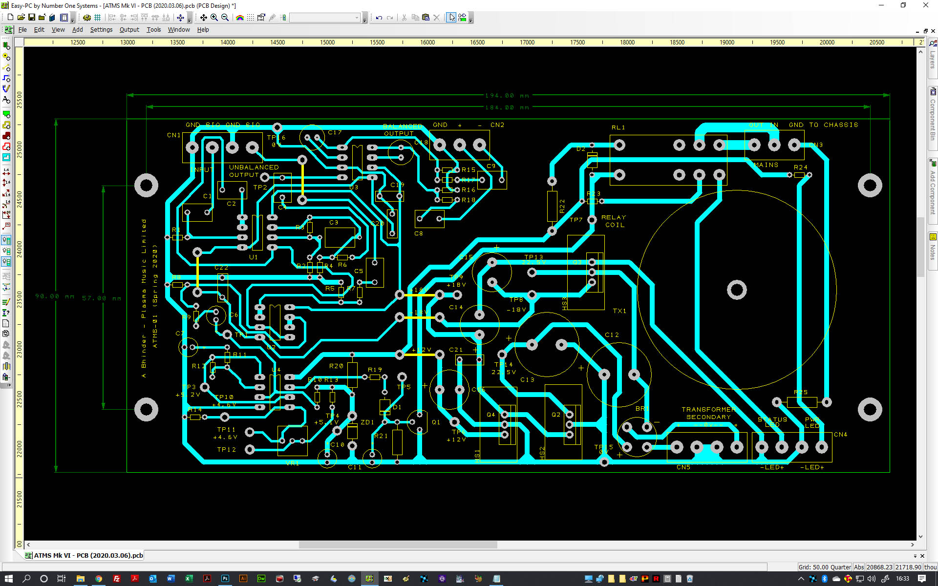
The PCB of the prototype audio triggered power switch was designed as a single-sided board.
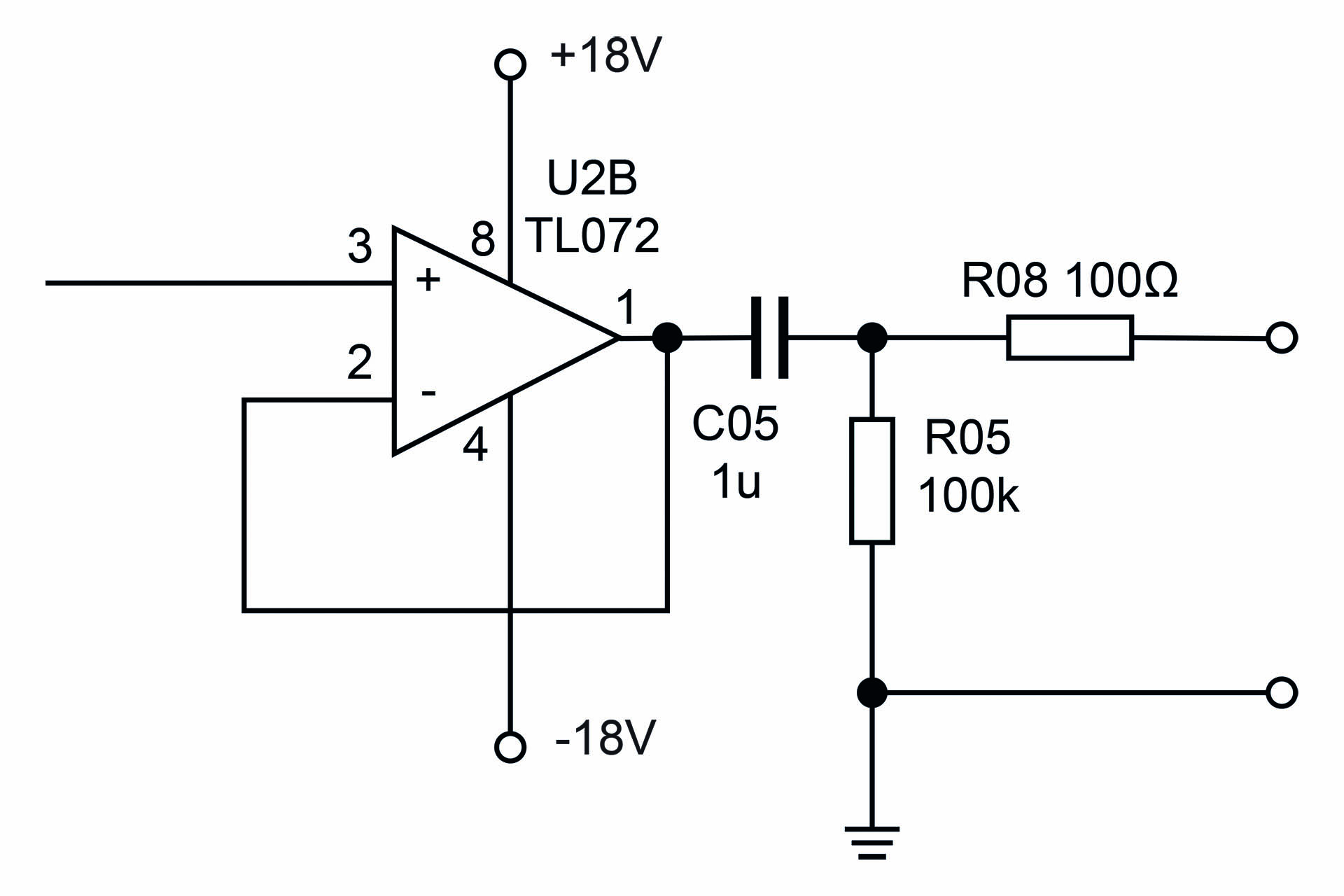
Over the past couple of weeks, I’ve been designing an audio triggered power switch; a gadget to switch on a power amp when an audio signal is detected and to wait a few minutes to switch off the power amp when no signal is present on the input.
The audio signal comes straight from the sub bass output of an A/V receiver amp and is therefore about -10dBV (approximately 310 mV) unbalanced. So apart from auto switch-on / switch-off, the circuit also amplifies the input signal to +4dBu (about 1.25 V) balanced which is whet the power amp wants to see on its inputs.
After testing a prototype for several months, this evening I ordered the PCB (the design of which is pictured above) for the final version.
SO WHAT'S THIS ACTUALLY USED FOR?
Well, the power amp in question, drives a sub-bass system on a home cinema. It's a big, professional amp and definitely wouldn't come with auto power-on / power-off or standby, which of course, the main (consumer) A/V receiver amp does have and which 99.9% of consumer sub-bass units have built-in.
The idea is that when the home cinema system is switched on, the power amp comes on when it detects a signal. When the system is switched off, the power amp switches off a few minutes later... PERFECT!
I wanted a minimal signal path for the audio that's being sent from the A/V receiver to the power amp, with just a little gain (-10dBm to +4dBm) and unbalanced to balanced conversion and I also wanted bags of headroom so the whole thing runs at +/-15V.
CREDITS
I don't see the point of reinventing the wheel, especially if someone has already designed something really good that works. Hence, the switching circuitry of this gadget is based on a design by Rod Elliot of Elliot Sound Products (see project 38). Rod puts up some fantastic, in-depth explanation into how the circuit works and how it can be tweaked to your specific requirements.
UPDATE - 18th February 2020
This morning, my PCBs arrived. I couldn't wait and quickly got down to populating one of them ready to test later in the afternoon.
Well, I'm pleased to report that all worked well. With a 1kHz sine wave, the sensitivity of the circuit is about 4.5mV and the delay to switch-off time is about ten minutes.
Unfortunately, the case I'll be using for this, is currently out of stock 'till 17th March, so it looks like this is going to sit on the shelf for a few weeks 🙁
UPDATE - 18th March 2020
Today I went over to RS Components in Watford to collect the enclosure that I'd planned to use for this project and the dimensions of which were part of the design of the PCB. Well, I couldn't believe what I was told; the boxes remain on back-order 'till, wait for it... 31st July. Seriously?!?!? I checked last night and there was no change in status. What the hell are you playing at?
This Roland VK-7 power supply rebuild started with my friend, Alex Richards bringing me his broken machine. The transformer is mounted upside-down on the inside of the top chassis. Guess what? It fell off! The machine was plugged in at the time so the accident caused considerable damage but luckily no one was injured.
To avoid this happening again, I mounted this heavy little component to the bottom (steel) chassis and laid new connections to the power supply board. Mounting the transformer to the chassis required some hole drilling but at least the transformer was undamaged. I don't think I would have been able to source a replacement if it wasn't.
Twenty years old, has taken quite a few knocks but it plays and sounds great. Check out more on the Roland VK-7 here.
If you have one of these and there's no power, perhaps you can hear or feel something loose inside, then contact me for a Roland VK-7 power supply rebuild.